

Page 1

Part Number: 71-0298RK
Revision: P1
65-2451RK-04
Hydrogen Transmitter
Operator’s Manual
Released: 11/8/13
RKI Instruments, Inc.
www.rkiinstruments.com
Page 2

WARNING
Read and understand this instruction manual before
operating transmitter. Improper use of the transmitter could
result in bodily harm or death.
Periodic calibration and maintenance of the transmitter is
essential for proper operation and correct readings. Please
calibrate and maintain this tra nsmitt er regula rly! Frequency
of calibration depends upon the type of use you have and
the sensor types. Typical calibration frequencies for most
applications are between 3 and 6 months, but can be
required more often or less often based on your usage.
65-2451RK-04 Hydrogen Transmitter
Page 3

Product Warranty
RKI Instruments, Inc. warrants gas alarm equipment sold by us to be free from defects in
materials, workmanship, and performance for a period of one year fr o m date of shipment
from RKI Instruments, Inc. Any parts found defective withi n tha t period will be repaired
or replaced, at our option, free of charge. This warranty does not apply to those items
which by their nature are subject to deterioration or consumption in normal ser v ice, and
which must be cleaned, repaired, or replaced on a routine basis. Examples of such items
are:
W arranty is voided by abuse including mechanical damage, alteration, rough handling, or
repair procedures not in accordance with the operator’s manual. This warranty indicates
the full extent of our liability , a nd we are not r esponsible for removal or r eplacement costs,
local repair costs, transportation costs, or contingent expenses incurred without our prior
approval.
a) Absorbent cartridges d) Batteries
b) Pump diaphragms and valves e) Filter elements
c) Fuses
THIS WARRANTY IS EXPRESSLY IN LIEU OF ANY AND ALL OTHER
WARRANTIES AND REPRESENTATIONS, EXPRESSED OR IMPLIED,
AND ALL OTHER OBLIGATIONS OR LIABILITIES ON THE PART OF
RKI INSTRUMENTS, INC. INCLUDING BUT NOT LIMITED TO, THE
WARRANTY OF MERCHANTABILITY OR FITNESS FOR A
PARTICULAR PURPOSE. IN NO EVENT SHALL RK I INSTRUMENTS,
INC. BE LIABLE FOR INDIRECT, INCIDENTAL, OR CONSEQUENTIAL
LOSS OR DAMAGE OF ANY KIND CONNECTED WITH THE USE OF
ITS PRODUCTS OR FAILURE OF ITS PRODUCTS TO FUNCTION OR
OPERATE PROPERLY.
This warranty covers instruments and parts sold to users by authorized distributors,
dealers, and representatives as appointed by RKI Instruments, Inc.
We do not assume i ndemnification for a n y a c c ident or damage cause d by the operation of
this gas monitor, and our warranty is limited to the replacement of parts or our complete
goods.
65-2451RK-04 Hydrogen Transmitter
Page 4

Table of Contents
Overview . . . . . . . . . . . . . . . . . . . . . . . . . . . . . . . . . . . . . . . . . . . . . . . . . . . . . . . . . . . . . . . . . . . 1
Specifications. . . . . . . . . . . . . . . . . . . . . . . . . . . . . . . . . . . . . . . . . . . . . . . . . . . . . . . . . . . . . . . . 1
Description. . . . . . . . . . . . . . . . . . . . . . . . . . . . . . . . . . . . . . . . . . . . . . . . . . . . . . . . . . . . . . . . . . 2
Hydrogen Detector. . . . . . . . . . . . . . . . . . . . . . . . . . . . . . . . . . . . . . . . . . . . . . . . . . . . . . . . . . . . . . . . . . . . 3
Calibration Cup/Splash Guard . . . . . . . . . . . . . . . . . . . . . . . . . . . . . . . . . . . . . . . . . . . . . . . . . . . . . . . . . 3
Amplifier . . . . . . . . . . . . . . . . . . . . . . . . . . . . . . . . . . . . . . . . . . . . . . . . . . . . . . . . . . . . . . . . . . . . . . . . . . . . 3
Amplifier Junction Box . . . . . . . . . . . . . . . . . . . . . . . . . . . . . . . . . . . . . . . . . . . . . . . . . . . . . . . . . . . . . . . . 4
Detector Junction Box. . . . . . . . . . . . . . . . . . . . . . . . . . . . . . . . . . . . . . . . . . . . . . . . . . . . . . . . . . . . . . . . . . 4
Installation . . . . . . . . . . . . . . . . . . . . . . . . . . . . . . . . . . . . . . . . . . . . . . . . . . . . . . . . . . . . . . . . . . 4
Mounting the Hydrogen Transmitter . . . . . . . . . . . . . . . . . . . . . . . . . . . . . . . . . . . . . . . . . . . . . . . . . . . . 4
Wiring the Detector to the Amplifier. . . . . . . . . . . . . . . . . . . . . . . . . . . . . . . . . . . . . . . . . . . . . . . . . . . . . 6
Wiring the Amplifier to a Controller . . . . . . . . . . . . . . . . . . . . . . . . . . . . . . . . . . . . . . . . . . . . . . . . . . . . . 8
Startup. . . . . . . . . . . . . . . . . . . . . . . . . . . . . . . . . . . . . . . . . . . . . . . . . . . . . . . . . . . . . . . . . . . . . 10
Introducing Incoming Power . . . . . . . . . . . . . . . . . . . . . . . . . . . . . . . . . . . . . . . . . . . . . . . . . . . . . . . . . . 10
Setting the Zero Signal. . . . . . . . . . . . . . . . . . . . . . . . . . . . . . . . . . . . . . . . . . . . . . . . . . . . . . . . . . . . . . . . 10
Maintenance. . . . . . . . . . . . . . . . . . . . . . . . . . . . . . . . . . . . . . . . . . . . . . . . . . . . . . . . . . . . . . . . 11
Preventive Maintenance . . . . . . . . . . . . . . . . . . . . . . . . . . . . . . . . . . . . . . . . . . . . . . . . . . . . . . . . . . . . . . 11
Troubleshooting . . . . . . . . . . . . . . . . . . . . . . . . . . . . . . . . . . . . . . . . . . . . . . . . . . . . . . . . . . . . . . . . . . . . . 13
Replacing Components of the Hydrogen Transmitter . . . . . . . . . . . . . . . . . . . . . . . . . . . . . . . . . . . . . 13
Calibration Frequency . . . . . . . . . . . . . . . . . . . . . . . . . . . . . . . . . . . . . . . . . . . . . . . . . . . . . . . 16
Determining Response Time . . . . . . . . . . . . . . . . . . . . . . . . . . . . . . . . . . . . . . . . . . . . . . . . . 16
Calibration . . . . . . . . . . . . . . . . . . . . . . . . . . . . . . . . . . . . . . . . . . . . . . . . . . . . . . . . . . . . . . . . . 17
Preparing for Calibration. . . . . . . . . . . . . . . . . . . . . . . . . . . . . . . . . . . . . . . . . . . . . . . . . . . . . . . . . . . . . . 17
Setting the Zero Reading. . . . . . . . . . . . . . . . . . . . . . . . . . . . . . . . . . . . . . . . . . . . . . . . . . . . . . . . . . . . . . 17
Setting the Response Reading. . . . . . . . . . . . . . . . . . . . . . . . . . . . . . . . . . . . . . . . . . . . . . . . . . . . . . . . . . 18
Returning to Normal Operation. . . . . . . . . . . . . . . . . . . . . . . . . . . . . . . . . . . . . . . . . . . . . . . . . . . . . . . . 18
Parts List . . . . . . . . . . . . . . . . . . . . . . . . . . . . . . . . . . . . . . . . . . . . . . . . . . . . . . . . . . . . . . . . . . . 19
65-2451RK-04 Hydrogen Transmitter
Page 5

Overview
This manual describe s the 65-2451RK- 04 hydro gen transmit ter . This manual al so describes
how to install, start up, configure, maintain, and calibrate the transmitter when it is used
with a gas monitoring controller. A parts list at the end of this manual lists replacement
parts and accessories for th e hydrogen transmitter.
Specifications
Table 1 lists specifications for the hydrogen transmitter.
Table 1:Specifications
Description Specification
Target Gas Hydrogen (H
Area Classification Explosionproof for Class I, Groups B, C, and D
Sampling Method Diffusion
Signal Output 4 to 20 mA
Detection Range 0 to 100% LEL
Response Time 90% in 45 seconds
Operating Temperature -4°F to 122°F (-20°C to 50°C)
Accuracy ± 5% of reading or ± 2% of full scale (whichever is gr eater)
)
2
WARNING: When using the 65-2451RK-04, you must follow the instructions and
warnings in this manual to assure proper and safe opera tion of the
65-2451RK-04 and to minimize the risk of personal injury. Be sure to
maintain and periodically calibrate the 65-2451RK-04 as described in this
manual.
65-2451RK-04 Hydrogen Transmitter • 1
Page 6
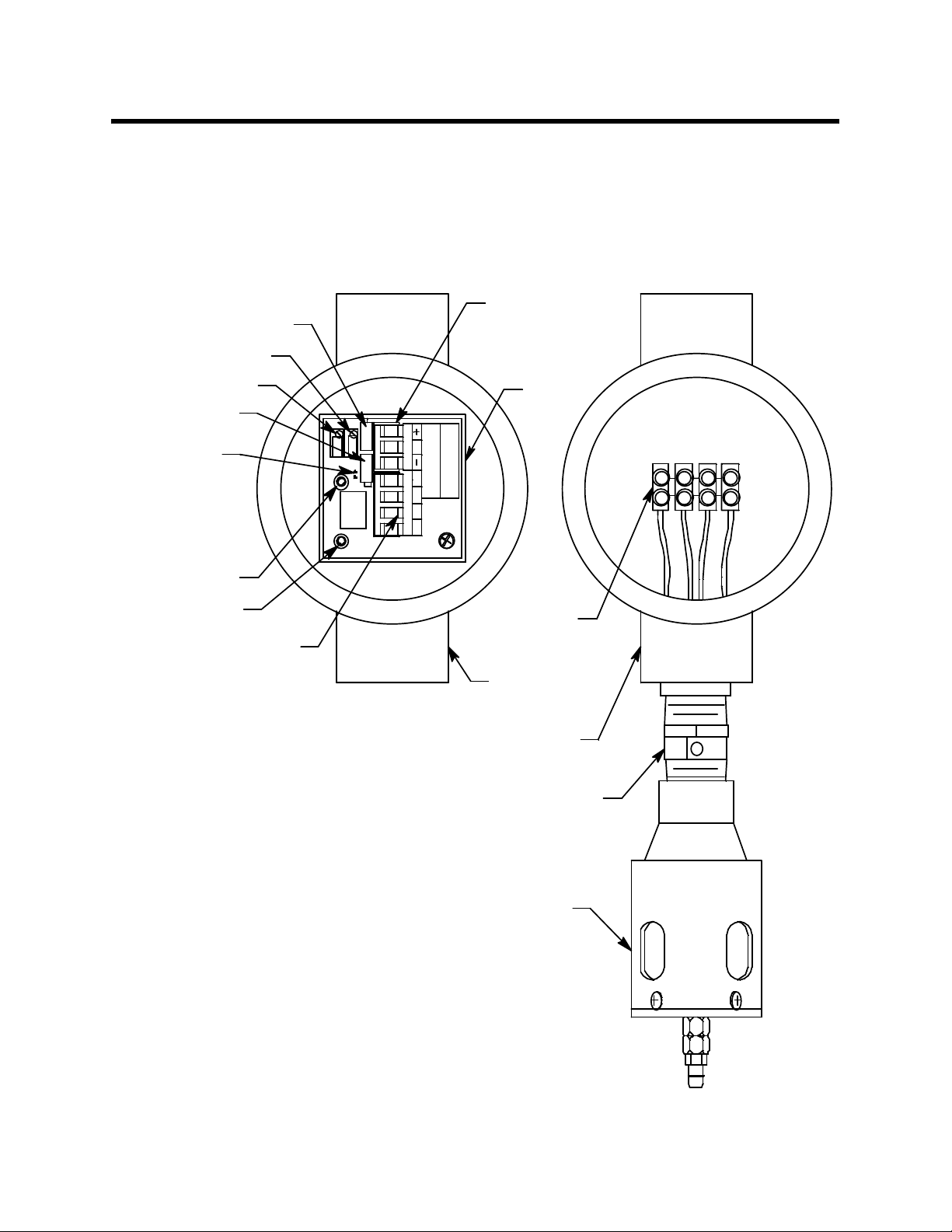
Description
Factory Adjust P ot
Span P ot
This section describes the components of the hydrogen transmitter. The transmitter is a 4 20 mA type detector head. It consists of the hydrogen detector, calibration cup/splash
guard, amplifier, the amplifier junction box, and the detector junction box. The two
junction box configuration is in tended for situations where the detector needs to be
installed at an inaccessible location. The detector junction box can be installed at the
inaccessible location and the amplifier junction box can be installed in a more readily
accessible area.
Controller Term inal
Strip
Zero Pot
Factory Adjust
Jump er Pin s,
Factory Use
Only
+ Test Point
- TestPoint
Detector Terminal
Pot
Strip
Am plif ier
SPAN
ZERO
Sensor
Current
m A
S
PWR / SIGLEL
57-1053RK
S2 001
GWRB
Terminal Strip
Am plif ier J- Box
Detector J-Box
Hydrogen Detector
Calibration Cup/Splash Guard
Figure 1: Hydrogen Transmitter Component Location
2 • 65-2451RK-04 Hydrogen Transmitter
Page 7

Hydrogen Detector
The hydrogen detector is a catalytic type detector that produces an electrical output that
corresponds to the detection range. It is packaged in a 1/2 inch NPT nipple with a
sintered metal flame arrestor on one end allowing ambient air to diffuse into the detector.
The flame arrestor also contains any sparks which may occur within the detector. The
detector has a built in molecular sieve that only allows hydrogen to diffuse into the
detector. The 1/2 inch NPT mounting threads at the top of the detector allow you to
mount it into the bottom conduit hub of the junction box. A rainshield screws onto the
bottom of the detector (flame arrestor end). The rainshield helps protect the detector from
rain and debris in the monitoring environment. Four color-coded leads extend from the
top of the detector. The leads allow you to connect the detector to the amplifier.
Calibration Cup/Splash Guard
A calibration cup/splash guard is installed on the rainshield of the hydrogen detector. A
fitting at the bottom of the calibration cup/splash guard allows a length of tubing to be
connected for calibr ation and routed to a more easily accessible location. The calibration
cup/splash guard also protects the detector.
Amplifier
The amplifier is located in the amplifier junction box. The amplifier converts the electrical
output from the detector to a 4 to 20 mA signal that corresponds to the detection range
and transmits the signal to a gas monitoring controller. A foam gasket that orients the
amplifier and keeps it from rotating is installed on the bottom of the amplifier. A label on
the amplifier indicates the detector drive current. This drive current is factory set and is
dictated by the combustible gas to which the detector is calibrated. Consult RKI
Instruments, Inc. if you plan to change the calibration gas for the transmitter, for example
from a hydrogen calibration to a methane calibration. The amplifier includes the detector
terminal strip, controller terminal strip, span pot, zero pot, and test points (see Figure 1).
Controller Terminal Strip
The controller terminal strip is a three position plug-in style terminal strip located near the
top of the amplifier. Use the controller terminal strip to wire the hydrogen transmitter to a
controller.
Detector Terminal Strip
The detector terminal strip is a four position plug-in style terminal strip located below the
controller terminal strip. Use the detector terminal strip to connect the hydrogen detector
to the amplifier.
NOTE: See “Wiring the Detector to the Amplifier” on page 6 for all wiring procedures
related to the transmitter.
Zero Pot
The zero pot is located in the upper left corner of the amplifier (see Figure 1). Use a small
flat blade screwdriver to turn the zero pot’s adjustment screw and adjust th e amplifier’s
zero (fresh air) output during the start-up and calibration procedures. Turn the adjustment screw clockwise to increase the zero output and counterclockwise to decrease the
zero output.
Span Pot
The span pot is located to the right of the zero pot (see Figure 1). Use a small flat blade
screwdriver to turn the span pot’s adjustment screw and adjust the amplifier’s gas
65-2451RK-04 Hydrogen Transmitter • 3
Page 8

response output during the calibration procedure. Turn the adjustment screw clockwise to
increase the gas response and counterclockwise to decrease the gas response.
CAUTION: The amplifier includes two additional potentiometers. They are factory-set. Do not
adjust them.
Test Points
The test points are on the left side of the amplifier (see Figure 1). The test points produce a
100 mV to 500 mV output that corresponds to the transmitter’s 4 to 20 mA output. Use the
test points and a voltmeter to measure the amplifier’s output during the start-up and
calibration procedures. The black test point in the lower left corner is the negative (-) test
point and the red test point below the zero pot is the positive (+) test point.
Amplifier Junction Box
The amplifier junction box protects the amplifier and wiring connections made to the
amplifier. Use the top 3/4’’ conduit hub to connect wiring from the amplifier to the
controller. Use the bottom 3/4” conduit hub to wire the remotely installed hydrogen
detector . Use the cover on the fr ont of the junction box to access the interior of the junction
box. The amplifier is factory installed in the junction bo x. Three spacers installed on the
back of the junction box controls the distance of the junction box from a mounting surface.
Installation
Detector Junction Box
The detector junction box is intended to be installed remotely from the amplifier junction
box. The hydrogen detector is factory installed in the bottom 3/4” conduit hub. A
terminal strip is provided for wiring connections and the detector is factory wired to one
side of this terminal strip. The other side of the terminal strip is for user-supplied wiring
to the detector terminal strip located in the amplifier junction box. This wiring should go
through the top 3/4” conduit hub. Three spacers installed on the back of the junction box
controls the distance of the junction box from a mounting surface.
This section describes procedures to mount the hydrogen transmitter in the monitoring
environment and wire the transmitter to a controller.
Mounting the Hydrogen Transmitter
1. Select a mounting site that is representative of the monitoring environment. Consider
the following when you select the mounting site.
• For the amplifier junction box, select a site where the junction box is not likely to
be bumped or disturbed. Make sure there is sufficient room to perform start-up,
maintenance, and calibration procedures. The site should be easily a ccessible.
• For the detector junction box, select a site where the target gas is likely to be found
first. For hydrogen, which is lighter than air, mount the transmitter near the ceiling or where hydrogen is most likely to accumulate.
• The junction boxes should be mounted no further than 200 feet from each other.
4 • 65-2451RK-04 Hydrogen Transmitter
Page 9

,
3/4 NPT
Female
3.65
.382.70
Rubber
Spacer
3X
10 .30 MAX
J-Box
Hydrogen
Detector
5.25
Calibration
Cup/Splash
Guard
Figure 2: Mounting the Hydrogen Transmitter
1.13
2. At the monitorin g site you select, hang or mount the detector junction box with the
detector facing down (see Figure 2).
3. Install 3/16 inch I.D. flexible polyurethane tubing to the fitting at th e botto m of the
calibration cup/splash guard and route it to an accessible area that is close to the
amplifier junction box. See the “Part s List” on page 19 for available tubing.
65-2451RK-04 Hydrogen Transmitter • 5
Page 10

Wiring the Detector to the Amplifier
WARN ING: Always verify that the power to the controller is off before you make
wiring connections.
1. Confirm that no power is being applied to the amplifier. If the amplifier has already
been connected to a controller, turn off the controller and turn off or unplug power to
the controller.
2. Remove the detector junction box’s cover from the junction box.
3. Remove the amplifier junction box’s cover from the junction box.
4. Guide a four-conductor, shielded cable or four wires in conduit through the top
conduit hub of the detector junction box. To make wiring more convenient, use wire
colors that correspond to the detector wire colors: red, white, green, and black.
NOTE: Consult RKI Instruments, Inc. for cable lengths longer than 200 feet.
5. Connect the detector leads to the terminal block in the detector junction box.
6. Secure the detector junction box’s cover to the junction box.
7. Guide the other end of the four-conductor, shielded cable or four wires in conduit
through the bottom conduit hub of the amplifier junction box.
8. To gain access to a plug-in terminal strip for wiring, pull it out of its socket by
grasping the terminal strip and pulling. The detecto r strip is keyed so that the
controller and detector terminal strips cannot be reversed inadvertently.
9. Pull out the detector terminal strip a nd co nnect the four wires to the terminal strip as
follows (see Figure 3).
• Connect the wire corresponding to the detector’s red wire to the LEL “R”
terminal.
• Connect the wire corresponding to the detector’s white wire to the LEL “W”
terminal.
• Connect the wire corresponding to the detector’s green wire to the LEL “G”
terminal.
• Connect the wire corresponding to the detector’s black wire to the LEL “B”
terminal.
CAUTION: If shielded cable is used, leave the cable shield ’s drain wire disconnected and
insulated at the detector junction box. You will connect the opposite end of the cable’s
drain wire to the amplifier junction box’s chassis (earth) ground.
6 • 65-2451RK-04 Hydrogen Transmitter
Page 11

Cable
Shield
Detector
Terminal
Strip
Amplifier
SBR G
PW R / SIG
Black
Green
LEL
W
White
Red
Black
Green
Amplifier
J-Box
White
Red
Detector J- Box
Hydrogen
Detector
Calibration Cup/Splash Guard
Figure 3: Wiring the Detector to the Amplifier
10. Reinstall the detector terminal strip into its socket.
11. If shielded cable is used, connect the cable’s drain wire to an available chassis (earth)
ground at the amplifier junction box. The amplifier mounting screw is a convenient
grounding location. Install a lug on the shield drain wire or wrap the shield drain wire
around the mounting screw. Do not connect the shield drain wire at the detector
junction box.
65-2451RK-04 Hydrogen Transmitter • 7
Page 12

Wiring the Amplifier to a Controller
1. Turn off the controller.
2. Turn off or unplug power t o the controller.
3. Remove the amplifier junction box’s cover from the junction box.
4. Guide a three-conductor, s hi elded cable, or three wires in conduit through the top
conduit hub of the amplifier junction box.
5. Pull out the controller terminal strip, and connect the three wires to the terminal strip
as follows (see Figure 4).
• Connect the positive wire to the PWR/SIG “+” terminal.
• Connect the signal wire to the PWR/SIG “S” terminal.
• Connect the negative wire to the PWR/SIG “-” terminal.
CAUTION: If shielded cable is used, leave the cable shield ’s drain wire disconnected and
insulated at the amplifier junction box. You will connect the opposite end of the
cable’s drain wire to the controller’s chassis (earth) ground.
6. Reinstall the controller terminal strip into its socket.
7. Secure the amplifier junction box’s cover to the junction box.
8. Route the cable or wires leading from the amplifier junction box through one of the
conduit hubs at the controller housing.
CAUTION: Do not route power and transmitter wiring through the same controller conduit hub.
The power cabl e may disrupt the transmission o f the transmitte r signal to the
controller.
9. Connect the wires to the applicable detector/transmitter terminal strip at the
controller as shown in Figure 4.
8 • 65-2451RK-04 Hydrogen Transmitter
Page 13

Amplifier
J-Box
+ 24 VDC
4 - 20 mA In (S)
- (DC Ground)
Cable Shield
Cont r o ller or
Recording Device
Amplifier (Transmitter)
S
PWR / SIG
B
LEL
R W G
Figure 4: Wiring the Amplifier to a Controller
Blac k
Gree n
White
Red
Detector Wires
10. If shielded cable is used, connect the cable’s drain wire to an available chassis (earth)
ground at the controller. RKI controllers typically have a ground stud that can be used
to ground the cable’s drain wire.
65-2451RK-04 Hydrogen Transmitter • 9
Page 14

Start Up
This section describes procedures to start up the hydrogen transmitter and place the
transmitter into normal operation.
Introducing Incoming Power
1. Complete the installati on procedures described earlier in this manual.
2. Veri fy that the power wiring to the controller is correct and secure. Refer to the
controller operator’s manual.
3. Turn on power to the controller.
4. Turn on the controller.
5. Verify that the controller is on and operating properly. Refer to the con troller
operator’s ma nual.
NOTE: When first powered up, the transmitter will enter about a one minute period
when the 4-20 mA output is stab ilizing and may be above the controller alarm
points or well below zero momentarily. RKI controllers have a one minute
warmup period when the controller does not display any gas reading or give any
alarm indication. The hydrogen transmitter’s 4-20 mA signal should be stable by
the time the controller’s warmup period is over.
CAUTION: Allow the detector to warm up for 5 minutes before you continue with the next
section, “Setting the Zero Signal”.
Setting the Zero Signal
WARN ING: Do not remove the junction box cover while the circuits are energized
unless the area is determined to be non-hazardous. Keep the junction box
cover tightly closed during operation.
NOTE: If you can verify that the hydrogen transmitter is in a fresh air environment, you
do not need to apply zero air to the detector before adjusting the zero reading.
The procedure below describes applying zero emission air, usually called zero air , using a
calibration kit that includes a calibration cup, calibration gas, sample tubing, and a fixed
flow regulator with an on/off knob. RKI Instruments, Inc. recommends using a 0.5 LPM
(liters per minute) fixed flow regulator.
1. Unscrew and remove the amplifier junction box’s cover from the junction box.
2. Set a voltmeter to measure in the millivolt (mV) range.
3. Plug the voltmeter leads into the test points on the amplifier. Plug the positive lead
into the red (+) test point; plug the negative lead into the black (-) test point.
4. Screw the regulator into the zero air calibration cylinder.
5. Use the flexible tubing comi ng f rom the calibration cup/splash guard to connect the
regulator to the calibration cup.
6. Turn the regulator’s on/o ff knob counterclockwise to open it. Gas will begin to flow.
10 • 65-2451RK-04 Hydrogen Transmitter
Page 15

7. Allow the gas to flow for the length of time determined in “Determining Response
8. Verify a voltmeter reading of 100 mV (±2 mV).
9. If necessary, use a s ma ll flat-blade screwdriver to adjust the zero pot until the
10. Turn the regulator’s on/off knob clockwise to close it.
11. Disconnect the calibration cup/splash guard’s flexible tubing from the regulator.
NOTE: Do not disconnect the flexible tubing from the calibration cup/splash guard.
12. Unscrew the regulator from the zero air calibration cylinder.
13. Store the components of the calibration kit in a safe and conve nient place.
14. Remove the voltmeter leads from the test points.
15. Secure the junction box cover to the junction box.
Maintenance
Tim e” on page 16.
voltmeter reading is 100 mV (±2 mV).
This section describes maintenance procedures. It includes preventive maintenance,
troubleshooting, and component replacement procedures.
Preventive Maintenance
This section describes a preventive maintenance schedule to ensure the optimum
performance of the hydrogen transmitter. It includes daily, monthly, and quarterly
procedures.
Daily
Verify a display reading of 0 %LEL at the controller. Investigate significant changes in the
display reading.
Monthly
This procedure describes a test to verify that the hydrogen transmitter responds properly
to the target gas.
WARN IN G: The controller is not an active gas monitoring device during the response
test procedure.
NOTE: Performing a response test on the hydrogen transmitter may cause alarms. Be
sure to put the controller into its calibration mode or disable external alarms
befor e per f o r ming this test.
NOTE: The following procedure assumes the use of a calibration kit which includes a
calibration gas cylinder, a 0.5 LPM fixed flow regulator with an on/off knob, a
calibration cup for the detector, and a length of sample tubing.
65-2451RK-04 Hydrogen Transmitter • 11
Page 16

Preparing for the response test
1. Place the controller into its calibration mode or disable external alarms.
2. Verify that the controller display reading for the channel you are testing is 0 % LEL.
If the display reading is not 0 %LEL, set the zero reading of the transmitter as
described in “Start Up” on page 10, then continue this procedure.
3. Screw the regulator into the calibration cylinder.
4. Use the flexible tubing comi ng f rom the calibration cup/splash guard to connect the
regulator to the calibration cup.
5. Unscrew and remove the amplifier junction box’s cover from the junction box.
6. Set a voltmeter to measure in the millivolt (mV) range.
7. Plug the voltmeter leads into the test points on the amplifier. Plug the positive lead
into the red (+) test point; plug the negative lead into the black (-) test point.
8. Use the following formula to determine the correct test points output for the test
sample.
Output (mV) = (calibrating sample/fullscale) X 400 + 100
For example, with a test sample of 50 %LEL and a fullscale setting of 100 %LEL, the
correct output is 300 mV.
300 (mV) = (50/100) X 400 +100
Performing the response test
1. Turn the regulator’s on/off knob counterclockwise to open the regulator. Gas will
begin to flow.
2. Allow the gas to flow for the length of time determined in “Determining Response
Tim e” on page 16.
3. Verify that the reading is within ± 20% of the response reading you determined earlier.
NOTE: If the reading is not within ± 20% of the correct response reading, calibrate the
transmitter as described in “Calibration” on page 17 of this manual.
4. Turn the regulator’s on/off knob clockwise to close the regulator.
5. Unscrew the regulator from the calibration cylinder.
6. Disconnect the calibration cup/splash guard’s flexible tubing from the regulator.
NOTE: Do not disconnect the flexible tubing from the calibration cup/splash guard.
7. Remove the voltmeter leads from the amplifier test points.
8. Reinstall the amplifier junction box’s cover.
9. When the controller display reading falls below the alarm setpoints, return the
controller to normal operation.
10. Store the components of the calibration kit in a sa fe place.
Quarterly
Calibrate the hydrogen transmitter as described in “Calibration” on page 17 of this
manual.
12 • 65-2451RK-04 Hydrogen Transmitter
Page 17

Troubleshooting
The troubleshooting guide describes symptoms, probable causes, and recommended
action for problems you may encounter with the hydrogen transmitter.
NOTE: This troubleshooting guide describes transmitter problems only. See the
controller operator’s manual for problems you may encounter with the
controller.
Table 2:Troubleshooting the Hydrogen Transmitter
Condition Symptom(s) Probable Causes Recommended Action
Fail Condition • Controller indicates a
Slow or No
Response/
Difficult or
Unable to
Calibrate
fail condition.
• Transmitter responds
slowly or does not
respond to response
test.
• Unable to accurately
set the zero or
response reading
during calibration.
• Transmitter requires
frequent calibration.
Note: Under “normal”
circumstances, the
transmitter requires
calibration once every 3
months.
Some applications
may require a more
frequent calibration
schedule.
• The detector-toamplifier or amplifie rto-controller wiring is
disconnected or
misconnected.
• The transmitter’s zero
reading is low enough
to cause a fail
condition.
• The transmitter is
malfunctioning.
• The calibration cylinder
is low, out-dated, or
defective.
• The calibration gas
flow rate is too low.
• The calibration gas is
not an appr opriate
concentration.
• The transmitter is
malfunctioning.
• The flexible tubing to
the calibration cup/
splash guard has
become kinked,
blocked, or
disconnected.
1. Verify that the detector-to-amplifier
and amplifier-to-controller wiring is
correct and secure.
2. Calibrate the transmitter.
3. If the fail condition continues, replace
the detector.
4. If the fail condition continues, contact
RKI for further instruction.
1. Verify that the calibration cylinder
contains an adequate supply of a
fresh test sample.
2. Verify that the regulator used for
calibration is a 0.5 LPM regulator.
3. Verify that the calibration gas
concentration is appropriate for the
transmitter. The concentration should
be in the detection range, preferably
about half of the detection range.
4. Verify that the flexible tubing to the
calibration cup/splash guard is clear
and connected to the calibration cup/
splash guard.
5. If the calibration/response difficulties
continue, replace the detector.
6. If the calibration/response difficulties
continue, contact RKI for further
instruction.
Replacing Components of the Hydrogen Transmitter
This section includes procedures to replace the hydrogen detector and amplifier.
Replacing the Hydrogen Detector
NOTE: The hydrogen detector is installed on the junction box that does not house the
amplifier. This junction box was likely installed somewhere difficult to access.
1. Turn off the controller.
2. Turn off or unplug power t o the controller.
3. Unscrew the calibration cup/splash guard from the detector.
4. Remove the detector junction box’s cover from the junction box.
65-2451RK-04 Hydrogen Transmitter • 13
Page 18

5. Disconnect the detector leads from the terminal block in the detector junction box.
Note the position of the color-coded leads as you remove them.
6. Unscrew the detector from the detector junction box.
7. Guide the detector leads of the replacement detector through the bottom conduit hub
of the detector junction box, then screw the mounting threads of the detector into the
conduit hub. If necessary for environmental conditions, apply thread s eal an t o r t eflon
tape to the hub and/or detector threads to seal them.
8. Connect the detector leads to the terminal block the same way the old detector was
wired (see Figure 3 on page 7).
9. Screw the calibration cup/splash guard onto the new det ect or.
10. Reinstall the detector junction box cover.
11. Turn on or plug in power to the co ntrol ler.
12. Turn on the controller and place it into normal operation.
NOTE: When first powered up, the transmitter will enter about a one minute period
when the 4-20 mA output is stab ilizing and may be above the controller alarm
points or well below zero momentarily. RKI controllers have a one minute
warmup period when the controller does not display any gas reading or give any
alarm indication. The hydrogen transmitter’s 4-20 mA signal should be stable by
the time the controller’s warmup period is over.
CAUTION: Allow the replacement detector to warm up for 5 minutes before you co ntinue with
the next step.
13. Calibrate the transmitter as described in “Calibration” on page 17 of this manual.
Replacing the Amplifier
NOTE: The amplifier is not housed in the same junction box as the hydrogen detector.
The amplifier junction box should be somewhere accessible.
1. Turn off the controller.
2. Turn off or unplug power t o the controller.
3. Remove the amplifier junction box’s cover from the junction box.
4. Unplug the detector terminal strip and controller terminal strip from their sockets.
You may leave the wires connected to the terminal strips.
5. Unscrew and remove the screw with the flat and lock washer s that secures the
amplifier to the junction box.
6. Remove the old amplifier.
7. Place the new amplifier in the same position as the old amplifier. A foam gasket that
orients the amplifier and keeps it from rotating is installed on the bottom of the
amplifier. Make sure the amplifier is seated flat in the junction box.
8. Install the new amplifier into the junction box w ith the screw, lock washer, and flat
washer you removed in step 5 above.
9. Install the detector and controller terminals strips into their sockets on the new
amplifier as shown in Figure 4 on page 9 of this manual. If controller leads or detector
14 • 65-2451RK-04 Hydrogen Transmitter
Page 19

leads were removed d uring this procedure, refer to Table 3 and Table 4 b elow.
Table 3:Reconnecting the Amplifier
to the Controller
Amplifier Controller
Te rminal Strip
PWR/SIG “-” - (DC -)
PWR/SIG “S” S (4 - 20 mA In)
PWR/SIG “+” + 24V
Table 4:Reconnecting the LEL
Detector to the Amplifier
Amplifier Detector
T erminal Strip
DETECTOR “R” RED
DETECTOR “W” WHT
DETECTOR “G” GREEN
DETECTOR “B” BLK
Controller
Transm itte r Terminal
Strip (typical)
Detector Lead
NOTE: When a transmitter is first powered up with a new amplifier, the initial output
may be either high or below zero depending on the setting of the zero pot. Be
sure to make arrangements so that this does not cause unwanted alarms.
10. Turn on pow er to the controller.
11. Turn on the controller and place it into normal operation.
NOTE: When first powered up, the transmitter will enter about a one minute period
when the 4-20 mA output is stab ilizing and may be above the controller alarm
points or well below zero momentarily. RKI controllers have a one minute
warmup period when the controller does not display any gas reading or give any
alarm indication. The hydrogen transmitter’s 4-20 mA signal should be stable by
the time the controller’s warmup period is over.
12. Allow the transmitter to warm-up for 5 minutes.
13. Calibrate the transmitter as described in “Calibration” on page 17 of this manual.
65-2451RK-04 Hydrogen Transmitter • 15
Page 20

Calibration Frequency
Although there is no particular calibration frequency that is correct for all applications, a
calibration frequency of every 3 to 6 months is adequate for most hydrogen transmitter
applications. Unless experience in a particular application dictates otherwise, RKI
Instruments, Inc. recommends a calibration frequency of every 3 months.
If an application is not very demanding, for example detection in a clean, temperature
controlled environment where hydrogen is not normally present and calibration
adjustments are minimal at calibration, then a calibration frequency of every 6 months is
adequate.
If an application is very demanding, for example if hydrogen is present often and in
significant concentrations or the environment is not well controlled, then more frequent
calibration than e v ery 3 mo nt h s m ay be n e ces s ary. If potential catalyst poisons are known
or likely to be present, more frequent calibration than every 3 months will be necessary.
Determining Response Time
Since the detector junction box is installed remotely from the amplifier, the response time
of the detector will depend on the length of flexible tubing that is attached to the
calibration cup/splash guard. To determine the response time based on the length of
tubing connected:
1. Place the controller into its calibration mode or disable external alarms.
2. Note the current gas reading displayed at th e controller.
3. Screw the regulator into the calibration cylinder. Do not use a zero air cylinder for this
operation.
4. Use the flexible tubing comi ng f rom the calibration cup/splash guard to connect the
regulator to the calibration cup.
5. Turn the regulator’s on/off knob counterclockwise to open the regulator. Gas will
begin to flow. Take note of the time or start a stopwatch.
6. When you first sta r t to notice an increase in the gas reading, note how much time
passed between starting the gas flow and noticing a reading response.
7. Turn the regulator’s on/off knob clockwise to close the regulator.
8. Unscrew the regulator from the calibration cylinder.
9. Disconnect the calibration cup/splash guard’s flexible tubing from the regulator.
NOTE: Do not disconnect the flexible tubing from the calibration cup/splash guard.
10. Add 1 minute to the length of time determined in step 6. This is the response time for
the detector. When performing a response test, zero adjustment, or span adjustment,
gas must be applied for this length of tim e .
16 • 65-2451RK-04 Hydrogen Transmitter
Page 21

Calibration
This section describes how to calibrate the hydrogen transmitter. It includes procedures to
prepare for calibration, set the zero reading, set the response rea d ing, and return to
normal operation.
W ARNING: The controller is not an active gas monitoring device during the calibration
procedure.
NOTE: The following procedure assumes the use of a calibration kit which includes a
calibration gas cylinder, a 0.5 LPM fixed flow regulator with an on/off knob, a
calibration cup for the detector, and a short piece of sample tubing to connect the
regulator to the calibration cup.
Prepari ng for Ca libration
1. Unscrew and remove the amplifier junction box’s cover from the junction box.
2. Set a voltmeter to measure in the millivolt (mV) range.
3. Plug the voltmeter leads into the test points on the amplifier. Plug the positive lead
into the red (+) test point; plug the negative lead into the black (-) test point.
4. Use the following formula to determine the correct test points output for the
calibrating sample.
Output (mV) = (calibrating sample/fullscale) X 400 + 100
For example, with a calibrating sample of 50 %LEL and a fullscale setting of
100 %LEL, the correct output is 300 mV.
300(mV) = (50/100) X 400 +100
5. Place the controller into its calibration mode or disable external alarms.
NOTE: Calibrating the hydrogen transmitter may cause alarms. Be sure to put the
controller into its calibration mode or disable external alarms before continuing.
Setting the Zero Reading
NOTE: If you can verify that the hydrogen transmitter is in a fresh air environment, you
do not need to apply zero air to the detector before adjusting the zero reading.
1. Screw the regulator into the zero air calibration cylinder.
2. Use the flexible tubing comi ng f rom the calibration cup/splash guard to connect the
regulator to the calibration cup.
3. Turn the regulator’s on/off knob counterclockwise to open the regulator.
4. Allow the gas to flow for the length of time determined in “Determining Response
Time” on page 16 and verify a reading of 100 mV (±2 mV). If necessary, use the zero
pot on the amplifier to adjust the reading to 100 mV (±2 mV).
5. Turn the regulator’s on/off knob clockwise to close the regulator.
6. Unscrew the regulator from the zero air calibration cylinder.
65-2451RK-04 Hydrogen Transmitter • 17
Page 22

7. Leave the calibration cup/splash guard’s flexible tubing con nected to the regulator.
Setting the Response Reading
1. Screw the regulator into the calibration cylinder. Verify that the calibration gas is
representative of the transmitter’s target gas.
2. Turn the regulator’s on/off knob counterclockwise to open the regulator.
3. Allow the calibration gas to flow for the length of time determined in “Determining
Response Time” on page 16 and verify that the reading matches the response reading
(±2 mV) you determined earlier. If necessary, use the span pot on the amplifier to
adjust the reading to match the correct response reading.
4. Turn the regulator’s on/off knob clockwise to close the regulator.
5. Unscrew the regulator from the calibration cylinder.
Returning to Normal Operation
1. Remove the voltmeter leads from the amplifier test points.
2. Disconnect the calibration cup/splash guard’s flexible tubing from the regulator.
NOTE: Do not disconnect the flexible tubing from the calibration cup/splash guard.
3. Secure the amplifier junction box cover to the junction box.
4. When the controller display reading falls below the alarm setpoints, return the
controller to normal operation.
5. Veri fy that the controller display reading decreases and stabilizes at 0 %LEL.
6. Store the components of the calibration kit in a safe and convenient place.
18 • 65-2451RK-04 Hydrogen Transmitter
Page 23

Parts List
Table 5 lists replacement parts and accessories for the hydrogen transmitter.
Table 5:Parts List
Part Number Description
06-1248RK Sample tubing (3/16 in. x 5/16 in.; specify length when ordering)
18-0400RK-01 Junction box with spacers
57-1053RK Amplifier with gasket (specify detector part number when ordering)
65-2451RK-04 Hydrogen transmitter (includes detector, two junction boxes, and amplifier)
71-0298RK 65-2451RK-04 Hydrogen Transmitter Operator’s Manual
(this document)
81-0002RK-01 Steel calibration cylinder, 50% LEL hydrogen in air, 34-liter
81-0076RK-01 Steel calibration cylinder, zero emission air, 34-liter
81-1050RK Regulator, 0.5 liter/minute; with pressure gauge and flow c ontr ol kn ob , for 17
81-1116RK Calibration cup/splash guard
81-F004RK-LV Calibration kit, includes regulator, sample tubing, calibration cup, and 34 liter
82-0006RK Pot adjust screwdriver, for calibration
NC-6205-01 Hydrogen LEL detector, 1/2 inch NPT
liter and 34 liter steel calibration cylinders
50 %LEL hydrogen in air steel calibration cylinder
65-2451RK-04 Hydrogen Transmitter • 19
 Loading...