

Page 1

65-2442RK
PPM Hydrogen Transmitter
Operator’s Manual
Part Number: 71-0139RK
Revision: 0
Released: 2/16/11
RKI Instruments, Inc.
www.rkiinstruments.com
Page 2

WARNING
Read and understand this instruction manual before operating
detector . Improper use of the dete ctor could result in bodily harm
or death.
Periodic calibration and maintenance of the detector is essential
for proper operation and correct readings. Please calibrate and
maintain this detector regularly! Frequency of calibration
depends upon the type of use you have and the sensor types.
T ypical calibration frequencies for most applications a re between
6 and 12 months, but can be required more often or less often
based on your usage.
65-2442RK PPM Hydrogen Transmitter
Page 3

Product Warranty
RKI Instruments, Inc. warrants gas alarm equipment sold by us to be free from defects in
materials, workmanship, and performance for a period of one year* from the date of
shipment from RKI Instruments, Inc. Any parts found defective within that period will be
repaired or replaced, at our option, free of charge. Parts must be returned to RKI
Instruments, Inc. for repair or replacement. This warranty does not apply to those items
which by their nature are subject to deterioration or consumption in normal service, and
which must be cleaned, repaired or replaced on a routine basis. Examples of such items
are:
a) Pump diaphragms and valves c) Batteries
b) Fuses d) Filter elements
Warranty is voided by abuse including mechanical damage, alteration, rough handling, or
repair procedures not in accordance with instruction manual. This warranty indicates the
full extend of our liability, and we are not responsible for removal or replacement costs,
local repair costs, transportation costs, or contingent expenses incurred without our prior
approval.
THIS WARRANTY IS EXPRESSLY IN LIEU OF ANY AND ALL OTHER
WARRANTIES AND REPRESENTATIONS, EXPRESSED OR IMPLIED, AND
ALL OTHER OBLIGATIONS OR LIABILITIES ON THE PART OF RKI
INSTRUMENTS, INC. INCLUDING BUT NOT LIMITED TO, THE WARRANTY OF
MERCHANTABILI TY OR FITNESS FOR A PARTICULAR PURPOSE. IN NO
EVENT SHALL RKI INSTRUMENTS, INC. BE LIABLE FOR INDIRECT,
INCIDENTAL OR CONSEQUENTIAL LOSS OR DAMAGE OF ANY KIND
CONNECTED WITH THE USE OF ITS PRODUCTS OR FAILURE OF ITS
PRODUCTS TO FUNCTION OR OPERATE PROPERLY.
This warranty covers instruments and parts sold to users only by authorized distributors,
dealers and representatives as appointed by RKI Instruments, Inc.
We do not assume indemnification for any accident or damage caused by the operation of
this gas monitor and our warranty is limited to the replacement of parts or our complete
goods. Warranty covers parts and labor performed at RKI Instruments, Inc. only, and does
not cover field labor or shipment of parts back to RKI.
65-2442RK PPM Hydrogen Transmitter
Page 4

Table of Contents
Overview . . . . . . . . . . . . . . . . . . . . . . . . . . . . . . . . . . . . . . . . . . . . . . . . . . . . . . . . . . . . . . . . . . . 1
Specifications. . . . . . . . . . . . . . . . . . . . . . . . . . . . . . . . . . . . . . . . . . . . . . . . . . . . . . . . . . . . . . . . 1
Description. . . . . . . . . . . . . . . . . . . . . . . . . . . . . . . . . . . . . . . . . . . . . . . . . . . . . . . . . . . . . . . . . . 2
PPM Hydrogen Detector . . . . . . . . . . . . . . . . . . . . . . . . . . . . . . . . . . . . . . . . . . . . . . . . . . . . . . . . . . . . . . . 2
Amplifier . . . . . . . . . . . . . . . . . . . . . . . . . . . . . . . . . . . . . . . . . . . . . . . . . . . . . . . . . . . . . . . . . . . . . . . . . . . . 3
Junction Box. . . . . . . . . . . . . . . . . . . . . . . . . . . . . . . . . . . . . . . . . . . . . . . . . . . . . . . . . . . . . . . . . . . . . . . . . . 4
Installation . . . . . . . . . . . . . . . . . . . . . . . . . . . . . . . . . . . . . . . . . . . . . . . . . . . . . . . . . . . . . . . . . . 4
Mounting the PPM Hydrogen Transmitter. . . . . . . . . . . . . . . . . . . . . . . . . . . . . . . . . . . . . . . . . . . . . . . . 4
Wiring the PPM Hydrogen Transmitter . . . . . . . . . . . . . . . . . . . . . . . . . . . . . . . . . . . . . . . . . . . . . . . . . . 5
Startup. . . . . . . . . . . . . . . . . . . . . . . . . . . . . . . . . . . . . . . . . . . . . . . . . . . . . . . . . . . . . . . . . . . . . . 7
Introducing Incoming Power . . . . . . . . . . . . . . . . . . . . . . . . . . . . . . . . . . . . . . . . . . . . . . . . . . . . . . . . . . . 7
Transmitter Burn-In Period . . . . . . . . . . . . . . . . . . . . . . . . . . . . . . . . . . . . . . . . . . . . . . . . . . . . . . . . . . . . . 7
Setting the Zero Signal. . . . . . . . . . . . . . . . . . . . . . . . . . . . . . . . . . . . . . . . . . . . . . . . . . . . . . . . . . . . . . . . . 7
Maintenance. . . . . . . . . . . . . . . . . . . . . . . . . . . . . . . . . . . . . . . . . . . . . . . . . . . . . . . . . . . . . . . . . 8
Preventive Maintenance . . . . . . . . . . . . . . . . . . . . . . . . . . . . . . . . . . . . . . . . . . . . . . . . . . . . . . . . . . . . . . . 8
Troubleshooting . . . . . . . . . . . . . . . . . . . . . . . . . . . . . . . . . . . . . . . . . . . . . . . . . . . . . . . . . . . . . . . . . . . . . 10
Replacing Components of the PPM Hydrogen Transmitter. . . . . . . . . . . . . . . . . . . . . . . . . . . . . . . . . 10
Setting the Detector Load Voltage . . . . . . . . . . . . . . . . . . . . . . . . . . . . . . . . . . . . . . . . . . . . . . . . . . . . . . 13
Calibration Frequency . . . . . . . . . . . . . . . . . . . . . . . . . . . . . . . . . . . . . . . . . . . . . . . . . . . . . . . 14
Calibration . . . . . . . . . . . . . . . . . . . . . . . . . . . . . . . . . . . . . . . . . . . . . . . . . . . . . . . . . . . . . . . . . 15
Calibration Kit Humidifier Tube . . . . . . . . . . . . . . . . . . . . . . . . . . . . . . . . . . . . . . . . . . . . . . . . . . . . . . . 15
Preparing for Calibration. . . . . . . . . . . . . . . . . . . . . . . . . . . . . . . . . . . . . . . . . . . . . . . . . . . . . . . . . . . . . . 15
Setting the Zero Reading. . . . . . . . . . . . . . . . . . . . . . . . . . . . . . . . . . . . . . . . . . . . . . . . . . . . . . . . . . . . . . 16
Setting the Response Reading. . . . . . . . . . . . . . . . . . . . . . . . . . . . . . . . . . . . . . . . . . . . . . . . . . . . . . . . . . 16
Returning to Normal Operation. . . . . . . . . . . . . . . . . . . . . . . . . . . . . . . . . . . . . . . . . . . . . . . . . . . . . . . . 16
Parts List . . . . . . . . . . . . . . . . . . . . . . . . . . . . . . . . . . . . . . . . . . . . . . . . . . . . . . . . . . . . . . . . . . . 17
65-2442RK PPM Hydrogen Transmitter
Page 5

Overview
This manual describes the 65-2442RK ppm hydrogen transmitter. This manual also
describes how to install, start up, con fi gure, mainta in, a nd ca librate the transmitter when
it is used with a gas monitoring controller. A parts list at the end of this manual lists
replacement parts and accessories for the transmitter.
Specifications
Table 1 lists specifications for the ppm hydrogen transmitter.
Description Specification
Table 1:Specifications
Target Gas Hydrogen (H
Detection Range 65-2442RK-1000: 0 - 1,000 ppm
65-2442RK-2000: 0 - 2,000 ppm
Area Classification Explosionproof for Class I, Groups B, C, and D
Sampling Method Diffusion
Signal Output 4 to 20 mA
Response Time 90% in 45 seconds
)
2
W ARNING: When using the 65-2442RK, you must follow the instructions and warnings
in this manual to assure proper and safe operation of the 65-2442RK and to
minimize the risk of personal injury. Be sure to maintain and period ically
calibrate the 65-2442RK as described in this manual.
65-2442RK PPM Hydrogen Transmitter • 1
Page 6

Description
Factory Adjust Pot
This sectio n des crib es the ppm hyd roge n tran smitter’s components. It is a 4 to 20 mA type
detector head. It consists of the ppm hydrogen detector, amplifier, and junction box.
SpanPot
Zero Pot
Load Voltage Pot
Factory Use
Jumper Strip
Factory Adjust Pot
- Test Point, Black
Gas Select Jumper,
In HydrogenPosition
+ Test Point, Red
Factory Use JumperStrip
ZERO
SPAN
as Select
1-2 Hex
G
134
2
Controller Terminal Strip
Detector Terminal Strip
Mounting Screw
w/ flat and lock washer
SWBR
PWR / SIG
3-4 H2
DETECTOR
Amplifier
J-Box
Reducing Bushing,
3/4 NPT to 1/2 NPT
Figure 1: PPM Hydrogen Transmitter Component Location
PPM Hydrogen Detector
The ppm hydrogen detector is a MOS type (metal oxide semiconductor) detector
packaged in a 1/2 inch NPT nipple with a sintered metal flame arrestor on one end
allowing ambient air to diffuse into the detector. The flame arres tor also contains any
sparks which may occur within the detector. The 1/2 inch NPT mounting threads at the
top of the detector allow you to mount it into the bottom conduit hub of the junction box.
A rainshield screws onto the bottom of the detector (flame arrestor end). The rainshield
helps protect the detector from rain and debris in the monitoring environment. Three
color-coded leads extend from the top of the detector. The leads allow you to connect the
detector to the amplifier.
2 • 65-2442RK PPM Hydrogen Transmitter
Hydrogen Detector
Page 7

The detector has a built in molecular sieve that only allows hyd rogen to diffuse into the
detector. The output of the detector is non-linear and is linearized by the amplifier (see
below).
Amplifier
The amplifier converts the non-linear electrical output from the detector to a linear 4 to 20
mA signal that corresponds to the detection range and transmits the signal to a gas
monitoring controller. The amplifier includes the terminal strips, gas select jumper strip,
span pot, zero pot, load voltage pot, and test points (see Figure 1).
Controller Terminal Strip
The controller terminal strip is a three position plug-in style terminal strip located near the
top of the amplifier. Use the controller terminal strip to wire the transmitter to a controller.
Detector Terminal Strip
The detector terminal strip is a three position plug-in style terminal strip located below
the controller terminal strip. Use the detector terminal strip to connect the detector to the
amplifier.
NOTE: The detector is factory-wired to the detector terminal strip. See the “Wiring the
PPM Hydrogen Transmi tter” o n pa ge 5 for all wiring procedures related to the
transmitter.
Gas Select Jumper Strip
The gas select jumper strip is a three position pin style terminal strip located in the lower
left corner of the amplifier. A label next to the jumper strip indicates which pins must be
shorted to select hexane or hydrogen. A jumper block is installed at the factory over pins 3
& 4 to select hydrogen as the gas type. The gas type defines the linearizing curve used by
the amplifier to linearize the detector output.
Zero Pot
The zero pot is located in the upper left corner of the amplifier (see Figure 1). Use a small
flat blade screwdriver to turn the zero pot’s adjustment screw and adjust the amplifier’s
zero (fresh air) output during the start-up and calibration procedures.
Span Pot
The span pot is located to the right of the zero pot (see Figure 1). Use a small flat blade
screwdriver to turn the span pot’s adjustment screw and adjust the amplifier’s gas
response output during the calibration procedure.
Load Voltage Pot
The load voltage pot is located below the zero and span pots (see Figure 1). The load
voltage pot is not needed for normal scheduled maintenance, so it is a right angle pot that
is not accessible unless the amplifier is lifted out of the junction box enough to access the
adjustment s crew. Use a small flat blade screwdrive r to turn the load voltage pot’s
adjustment screw and adjust the amplifier’s detector load voltage when the detector or
amplifier is replaced.
CAUTION: The amplifier includes additional pots. They are factory-set. Do not adjust the m.
65-2442RK PPM Hydrogen Transmitter • 3
Page 8

Installation
Test Points
The test points are in the lower left corner of the amplifier on either side of the gas se lect
jumper strip (see Figure 1). The test points produce a 100 to 500 mV output that
corresponds to the transmitter’s 4 to 20 mA output. Use the test points and a voltmeter to
measure the amplifier’s output during the start-up and calibration procedures. The black
test point on the left is the negative (-) test point and the red test point on the right is the
positive (+) test point.
Junction Box
Use the junction box to install the transmitter at a mounting site that is remote from the
controller. The junction box also protects the amplifier and wiring connections made to
the amplifier. Use the top 3/4 inch conduit hub to connect wiring from the amplifier to the
controller. Use the cover on the f ront of the junction box to access the interior of the
junction box. The detector and amplifier are factory installed in the junction box.
This section describes procedures to mount the ppm hydrogen transmitter in the
monitoring environment and wire the transmitter to a controller.
Mounting the PPM Hydrogen Transmitter
3/4 NPT Female
.382.70
3.65
7.5 max
Rubber
Spacers,
3X
J Box
3/4 x 1/2 Reducing
Bushing
Figure 2: Mounting the PPM Hydrogen Transmitter
4 • 65-2442RK PPM Hydrogen Transmitter
Hydrogen
Detector
.75
Page 9

1. Select a mounting site that is representative of the monitoring environment. Consider
the following when you select the mounting site.
• Select a site where the transmitter is not likely to be bumped or disturbed. Make
sure there is sufficient room to perform start-up, maintenance, and calibration
procedures.
• Select a site where the target gas is likely to be found first. For hydrogen, which is
lighter than air , mount the transmitter near the ceiling or where hydr ogen is most
likely to accumulate.
2. At the monitoring site you select, hang or mount th e jun c tion box with the detector
facing down (see Figure 2).
Wiring the PPM Hydrogen Transmitter
WARN IN G: Always verify that the power to the controller is off before you make
wiring connections.
1. Turn off power to the controller.
2. Place the controller’s power switch in the OFF position.
3. Remove the junction box cover.
4. The detector leads are factory wired. Verify that the detector leads are wired to the
amplifier’s detector terminal strip as shown in Figure 3.
5. To gain access to a plug-in terminal strip for wiring, pull it out of its socket by
grasping the terminal strip and pulling. The detecto r strip is keyed so that the
controller and detector terminal strips cannot be reversed inadvertently.
6. Guide a three-conductor, s hielded cable or three wires in conduit through the top
conduit hub of the junction box.
7. Pull out the controller terminal strip, and connect the three wires to the terminal strip
as follows (see Figure 3 ).
• Connect the positive wire to the PWR/SIG “+” terminal.
• Connect the signal wire to the PWR/SIG “S” terminal.
• Connect the negative wire to the PWR/SIG “-” terminal.
CAUTION: If shielded cable is used, leave the cable shield’s drain wire disconnected and
insulated at the transmitter. You will connect the opposite end of the cable’s drain
wire to the controller’s chassis (earth) ground.
8. Reinstall the controller terminal strip into its socket.
9. Secure the junction box cover to the junction box.
10. Route the cable or wires leading from the ppm hydrogen transmitter through one of
the conduit hubs at the controller housing.
CAUTION: Do not route power and transmitter wiring through the same controller conduit hub.
The power cabl e may disrupt the transmission of the transmitter signal to the
controller.
65-2442RK PPM Hydrogen Transmitter • 5
Page 10

11. Connect the wires to the applicable detector/transmitter terminal strip at the
controller as shown in Figure 3.
+ 24 VDC
4- 20mAIn (S)
- (DC Ground)
Controller
Cable Shield
GasSelect Jum per,
In Hydrogen Position
S
PWR / SIG
1-2 Hex
Gas Select
243
1
RB
W
3-4 H2
DETECTOR
Red
Black
White
Detector Wires
Figure 3: Wiring the PPM Hydrogen Transmitter to a Controller
12. If shielded cable is used, connect the cable’s drain wire to an available chassis (earth)
ground at the controller. RKI controllers typically have a ground stud that can be used
to ground the cable’s drain wire.
6 • 65-2442RK PPM Hydrogen Transmitter
Page 11

Start Up
This secti on describes proce d u res to start up the ppm hydrogen transmitter and place the
transmitter into normal operation.
Introducing Incoming Power
1. Complete the installation procedures described earlier in this manual.
2. Verify that the power wiring to the controller is correct and secure. Refer to the
controller operator’s manual.
NOTE: When a transmitter is first powered up after installation or being off power for an
extended period, its signal will increase rapidly over a few seconds to a hi gh
level and then the signal will decrease so that it appears stable after a few
minutes. Be sure to make arrangements so that this does not cause unwanted
alarms.
3. Turn on pow er to the controller.
4. Turn on the controller.
5. Verify that the controller is on and operating properly. Refer to the controller
operator’s manual.
Transmitter Burn-In Period
Once power has been applied to the transmitter, it will take several days for the
transmitter signal to the controller to stabiliz e completely. This is the burn-in period. The
zero reading may be slightly above zero after startup and will stabilize in about 5 to 7
days. The transmitter is calibrated at the factory before shipment and it is not necessary to
calibrate the transmitter after startup. If calibration of the transmitter after startup is
desired, wait at least 5 days after startup before calibrating the transmitter. A burn-in
period of 7 days is recommended. See “Calibration” on page 15 for c alibration
instructions.
After the burn-in period, set the zero reading if necessar y as described in “Calibration” on
page 15.
CAUTION: Do not adjust the zero or span potentiometers for at least 5 days after startup.If the
fresh air reading is high eno ugh to cause unwant ed alarms during the burn-in
period, adjust the zero pot only enough to bring the reading below the alarm point.
Setting the Zero Signal
CAUTION: If you suspect the presence of hydrogen in the monitoring environment, use the
calibration kit and the zero air calibration cylinder to introduce “fresh air” to t he
detector and verify an accurate zero setting. See “Calibration” on page 15 for
instructions to apply zero air when setting the ze ro signal.
1. Verify that the transmitter is in a fresh air environment (environment known to be free
of hydrogen).
2. Unscrew and remove the junction box cover from the junction box.
3. Set a voltmeter to measure in the millivolt (mV) range.
65-2442RK PPM Hydrogen Transmitter • 7
Page 12

4. Plug the voltmeter leads into the test points on the amplifier. Plug the positive lead
5. Veri fy a voltmeter reading of 100 mV (±2 mV).
6. If necessary, use a small flat-blade screwdriver to adjust th e zero pot until the
7. Remove the voltmeter leads from the test points.
8. Secure the junction box cover to the junction box.
Maintenance
This section describes maintenance procedures. It includes preventive maintenance,
troubleshooting, and component replacement procedures.
Preventive Maintenance
This section describes a preventive maintenance schedule to ensure the optimum
performance of the ppm hydrogen transmitter. It includes daily, monthly, and qu arterly
procedures.
Daily
into the red + test point; plug the negative lead into the black - test point.
voltmeter reading is 100 mV (±2 mV).
Verify a display reading of 0 ppm at the controller. Investigate significant changes in the
display reading.
Monthly
This procedure describes a test to verify that the ppm hydrogen transmitter responds
properly to the target gas.
WARNING: The controller is not an active gas monitoring device during the response
test procedure.
NOTE: Performing a response test on the ppm hydrogen transmitter may cause alarms.
Be sure to put the controller into its calibration mode or disable external alarms
before performing this test.
NOTE: The following procedure assumes the use of a calibration kit which includes a
calibration gas cylinder, a 0.5 LPM fixed flow regulator with an on/off knob, a
calibration cup for the detector, and a humidifier tube to connect the regulator to
the calibration cup.
Preparing for the response test
1. Place the controller into its calibration mode or disable external alarms.
2. Verify that the controller display reading for the channel you are testing is 0 ppm.
If the display reading is not 0 ppm, set the zero reading of the transmitter as described
in “Start Up” on page 7, then continue this procedur e.
3. Screw the calibration cup onto the bottom of the detector.
4. Use the humidifier tube to connect the regulator to the calibration cup.
5. Set a voltmeter to measure in the millivolt (mV) range.
8 • 65-2442RK PPM Hydrogen Transmitter
Page 13

6. Remove the junction box cover, then plug the voltmeter leads into the test points on
the amplifier.
Plug the positive lead into the red + test point; plug the negative lead into the black test point.
7. Use the following formula to determine the correct test points output for the test
sample.
Output (mV) = (calibrating sample/fullscale) X 400 + 100
For example, with a te st sam ple o f 1, 000 ppm hydr og en an d a fu lls cale se tti ng of 2 ,000
ppm hydrogen, the correct output is 300 mV.
300 (mV) = (1000/2000) X 400 +100
Performing the response test
1. Screw the regulator into the calibration cylinder.
2. Turn the regulator knob counterclockwise to open the regulator.
3. Allow the gas to flow for one minute.
4. Verify that the reading is withi n ± 2 0% of the response reading you determined
earlier.
NOTE: If the reading is not within ± 20% of the correct response reading, calibrate the
transmitter as described in “Calibration” on page 15 of this manual.
5. Turn the regulator knob clockwise to close the regulator.
6. Unscrew the regulator from the calibration cylind er.
7. Unscrew the calibration cup from the detector.
NOTE: For convenience, leave the regulator and calibration cup connected by the
humidifier tube.
8. Remove the voltmeter leads from the amplifier test points.
9. Reinstall the junction bo x cover.
10. When the controller display reading falls below th e alarm setpoints, return the
controller to normal operation.
11. Store the components of the calibration kit in a sa fe place.
Biannual
Calibrate the ppm hydrogen transmitter as described in “Calibration” on page 15.
65-2442RK PPM Hydrogen Transmitter • 9
Page 14

Troubleshooting
The troubleshooting guide describes symptoms, probable causes, and recommended
action for problems you may encounter with the ppm hydrogen transm itter.
NOTE: This troubleshooting guide describes transmitter problems only. See the
controller operator’s ma nual for problems you may encounter with the
controller.
Table 2:Troubleshooting the ppm Hydrogen Transmitter
Condition Symptom(s) Probable Causes Recommended Action
Fail
Condition
Slow or No
Response/
Difficult or
Unable to
Calibrate
• Controller indicates a
fail condition.
• Transmitter responds
slowly or does not
respond to response
test.
• Unable to accurately
set the zero or
response reading
during calibration.
• Transmitter requires
frequent calibration.
Note: Under “normal”
circumstances, the
transmitter requires
calibration once every 6
months.
Some applicatio ns may
require a more frequent
calibration schedule.
• The transmitter wiring
is disconnected or
misconnected.
• The transmitter’s zero
reading is low enough
to cause a fail
condition.
• The transmitter is
malfunctioning.
• The calibration cylinder
is low, out-dated, or
defective.
• The calibration gas
flow rate is too low.
• The transmitter is
malfunctioning.
1. Verify that the transmitter wiring is
correct and secure.
2. Calibrate the transm itt er.
3. If the fail condition continues, replace
the detector.
4. If the fail condition continues, contact
RKI for further instruction.
1. Verify that the calibration cylinder
contains an adequate supply of a
fresh test sample.
2. Verify that the regulator used for
calibration is a 0.5 LPM regulator.
3. If the calibration/response difficulties
continue, replace the detector.
4. If the calibration/response difficulties
continue, contact RKI for further
instruction.
Replacing Components of the PPM Hydrogen Transmitter
This section includes procedures to replace the ppm hydrogen detector and am plifier.
Replacing the PPM Hydrogen Detector
1. Turn off power to the controller.
2. Place the controller’s on/off switch in the OFF position.
3. Remove the junction box cover.
4. Remove the detector terminal strip from its socket.
5. Disconnect the detector leads from the detector terminal strip. Note the position of the
color-coded leads as you remove them.
6. Unscrew the detector from the junction box.
7. Guide the detector leads of the replacement detector through the bottom conduit hub
of the junction box, then screw the mounting threads of the detector into the conduit
10 • 65-2442RK PPM Hydrogen Transmitter
Page 15

hub.
8. Connect the detector leads to the detector terminal strip as shown in Table 3 below
and Figure 3 o n page 6 of this manual.
Table 3:Reconnecting the PPM Detector to the Amplifier
Detector Lead
Red DETECTOR “R”
White DETECTOR “W”
Black DETECTOR “B”
Amplifier Interconnect
Terminal Strip
9. Re-install the detector terminal strip into its so cket.
NOTE: When a transmitter is first powered up with a new detector, its signal will
increase rapidly over a few seconds to a high level an d then the signal will
decrease so that it appears stable after a few minutes. Be sure to make
arrangements so that this does not cause unwanted alarms.
10. Turn on pow er to the controller.
11. Turn on the controller and place it into normal operation.
12. Allow the transmitter to run for 3 hours.
13. Make a preliminary setting of the sensor load voltage. See “Setting the Detector Loa d
Voltage” on page 13. This will be a temporary load voltage setting since the load
voltage will need to be set again after the burn-in period as described below.
14. Perform a preliminary calibration. See “Calibration” on page 1 5. This will be a
temporary calibration since the new ppm detector must burn-in before it can be
properly calibrated.
15. Allow the replacement detector to burn-in for at least 5 days before you continue with
the next step. A burn-in period of 7 days is recommended.
16. After the burn-in period, set the load voltage as described in “Setting the Detector
Load Voltage” on page 13.
17. After setting the load voltage, calibrate the transmitter as described in “Calibration”
on page 15 of this manual.
Replacing the Amplifier
If you are replacing the amplifier, it is likely that the transmitter has been off power for an
extended period. Make sure to follow the preliminary load voltage and preliminary
calibration recommendations and the burn-in period recommendation before making the
final load voltage setting and cal ibration.
1. Turn off power to the controller.
2. Place the controller’s on/off switch in the OFF position.
3. Remove the junction box cover.
4. Unplug the detector terminal strip and controller terminal strip from their sockets.
You may leave the wires connected to the terminal strips.
5. Unscrew and remove the screw with the flat and lock washers that secures the
65-2442RK PPM Hydrogen Tra nsm itter • 11
Page 16

amplifier to the junction box.
6. Remove the old amplifier.
7. Install the detector and controller terminal strips into their socket s on the new
amplifier as shown in Figure 3 on page 6 of this manual. If controller leads or detector
leads were re moved during this procedure, refer to Tables 4 and 5 below.
Table 4:Reconnecting the PPM Hydrogen Amplifier
to the Controller
Amplifier Power
Interconnect Terminal
Block
PWR/SIG “-”
PWR/SIG “S” S (4 - 20 mA In)
PWR/SIG “+” + 24V
Table 5:Reconnecting the PPM Hydrogen
Detector to the Amplifier
Detector Lead
DETECTOR “R” RED
DETECTOR “W” WHT
DETECTOR “B” BLK
Controller
Transm itte r Terminal
Strip (typical)
- (DC -)
Amplifier Interconnect
Te rminal Strip
8. Lay the new amplifier in the junction box. Do not re-install th e am plif ier in the
junction box with the screw, flat washer, an d lock washer yet because you will need to
pull it out for access to the load voltage adjust pot below.
NOTE: When a transmitter is first powered up with a new amplifier, the initial output
may be either high or below zero. Be sure to make arrangements so that this does
not cause unwanted alarms.
9. Turn on pow er to the controller.
10. Turn on the controller and place it into normal operation.
11. Allow the transmitter to run for 3 hours.
12. Make a preliminary setting of the sensor load voltage. See “Setting the Detector Loa d
Voltage” on page 13. This will be a temporary load voltage setting since the load
voltage will need to be set again after the burn-in period as described below.
13. Install the amplifier into the junction box with the screw , lo ck washer, and flat washer
you removed in Step 5 above. A foam gasket that orients the amplif ier and keeps it
from rotating is installed on the bottom of the ampli fi e r. Make sure the amplifier is
seated flat in the junction box.
14. Perform a preliminary calibration. See “Calibration” on page 1 5. This will be a
temporary calibration since the new ppm detector must burn-in before it can be
properly calibrated.
12 • 65-2442RK PPM Hydrogen Transmitter
Page 17

15. Allow the replacement detector to burn-in for at least 5 days before you continue with
the next step. A burn-in period of 7 days is recommended.
16. After the burn-in period, set the load voltage as described in “Setting the Detector
Load Voltage” on page 13.
17. After setting the load voltage, calibrate the transmitter as described in “Calibration”
on page 15 of this manual.
Setting the Detector Load Voltage
The detector load voltage must be reset when the detector or amplifier is replaced or if
you suspect that it has been ch anged from the factory setting for your detection range.
This procedure involves setting a voltage while applying calibration gas to the detector
that matches the full-scale concentration for the transmitter. After repla cing the detector or
amplifier as described earlier in this manual, the following procedure must be completed
before calibrating the sensor. Be sure to follow the timing recommendations in “Replacing
the PPM Hydrogen Detector” on page 1 0 and “ Replacing the Amplifier” on page 11 for
setting the load voltage.
WARN IN G: The controller is not an active gas monitoring device during the loa d
voltage setting procedure.
NOTE: The following procedure assumes the use of a calibration kit which includes a
calibration gas cylinder equal to the transmitter’s full scale gas concentra tion, a
0.5 LPM fixed flow regulator with an on/off knob, a calibration cup for the
detector, and a hu midifier tube to connect the regulator to the calibration cup.
1. Screw the calibration cup onto the bottom of the hydrogen detector.
2. Use the humidifier tube to connect the regulator to the calibration cup.
3. Set a voltmeter to measure in the DC volt range.
4. Remove the junction box cover.
5. Remove the screw , flat washer, and lock washer retaining the amplifier to the junction
box, and carefully lift the amplifier to gain access to the load voltage adjustment pot.
See Figure 1 for the pot location.
6. Screw the regulator into the calibration gas cylinder . The cylinder must be equal to the
transmitter’s full scale gas concentration.
7. Turn the regulator knob counterclockwise to open the regulator.
8. Allow the calibration gas to flow for one minute.
65-2442RK PPM Hydrogen Tra nsm itter • 13
Page 18
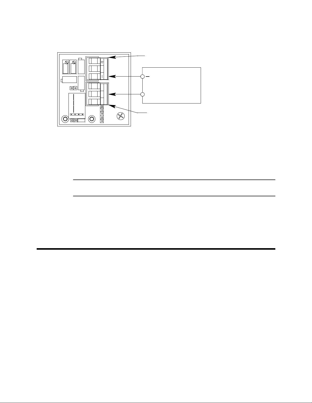
9. Measure the voltage between the B terminal on the detector terminal strip and the (negative) terminal on the controller terminal strip as shown belo w in Figure 4.
Controller Terminal Str ip
ZERO
SPAN
1-2 Hex
3-4 H2
as Select
G
134
2
SWBR
PWR / SIG
Digital
Voltmeter
Measure Load Voltage
Between B and -
+
D ETECTOR
Detector Terminal Strip
NOTE: Detector and Controller Wires Not Shown
Figure 4: Load Voltage Measurement
10. Adjust the load voltage adjust pot until the load voltage is 5.0 V ± 0.1 V.
11. Turn the regulator knob clockwise to close the regulator.
12. Unscrew the regulator from the calibration cylinder.
13. Unscrew the calibration cup from the detector
NOTE: For convenience, leave the regulator and calibration cup connected by the
humidifier tube.
14. Re-install the amplifier to the housing using the screw, flat washer, and lock washer
removed in Step 5 above.
15. Calibrate the ppm hydrogen transmitter as described in “Calibration” on page 15.
16. Verify that the controller display reading decreases and stabilizes at 0 ppm.
17. Store the components of the calibration kit in a safe and convenient place.
Calibration Frequency
Although there is no particular calibration frequency that is correct for all ppm hydrogen
transmitter applications, a calibration frequency of every 6 to 12 months is adeq uate for
most applications. Unless experience in a particular application dictates otherwise, RKI
Instruments, Inc. recommends a calibration frequency of every 6 months.
If an application is not very demanding, for example detection in a clean, temperature
controlled environment where hydrogen is not normally present, and calibration
adjustments are minimal at calibration, then a calibration frequency of every 12 months is
adequate.
If an application is very demanding, for example if hydrogen is present often and in
significant concentrations or the environment is not well controlled, then more frequent
calibration than every 6 months may be necessary.
14 • 65-2442RK PPM Hydrogen Transmitter
Page 19

Calibration
This section describes how to calibrate the ppm hydrogen transmitter. It includes
procedures to prepare for calibration, set the zero reading, set the response reading, and
return to normal operation.
W ARNING: The controller is not an active gas monitoring device during the calibration
procedure.
NOTE: The following procedure assumes the use of a calibration kit which includes a
calibration gas cylinder, a 0.5 LPM fixed flow regulator with an on/off knob, a
calibration cup for the detector, and a humidifier tube to connect the regulator to
the calibration cup.
Calibration Kit Humidifier Tube
The ppm hydrogen detector requires normal atmospheric humidity levels to respond
properly to hydrogen. Normal atmospheric humidity variations do not affect the
detector’s response to hydrogen in ambient air, but the ultra low humidity level of gas
from a calibration cylinder requires that the calibration sample be humidified for the
detector to respond properly. The calibration kit for the ppm hyd rogen transmitter
includes a humidifier tube that is not normally included in other calibration kits. This
humidifier tube humidifies the calibration sample flowi ng through it by absorbing
humidity from the ambient air and adding it to the sample. The humidifier tube is
included in the “Parts List” on page 17.
WARNING: A humi di fier tube must be used when calibrating the ppm hydrogen
transmitter test for the detector to respond properly to the cali br ation gas.
Failure to use a humidifier tube will result in an inaccurate cal ibration.
Prepari ng for Ca libration
1. Screw the calibration cup onto the bottom of the hydrogen detector.
2. Use the humidifier tube to connect the regulator to the calibration cup.
3. Set a voltmeter to measure in the millivolt (mV) range.
4. Remove the junction box cover, then plug the voltmeter leads into the test points on
the amplifier.
Plug the positive lead into the red + test point; plug the negative lead into the black test point.
5. Use the following formula to determine the correct test points output for the
calibrating sample.
Output (mV) = (calibrating sample/fullscale) X 400 + 100
For example, with a calibrating sample of 1,000 ppm hydrogen and a fullscale setting
of 2,000 ppm hydrogen, the correct output is 300 mV.
300(mV) = (1000/2000) X 400 +100
6. Place the controller into its calibration mode or disable external alarms.
65-2442RK PPM Hydrogen Tra nsm itter • 15
Page 20

NOTE: Calibrating the ppm hydrogen transmitter may cause alarms. Be sure to put the
controller into its calibration program or disable external alarms before
continuing.
Setting the Zero Reading
NOTE: If you can verify that the ppm hydrogen transmitter is in a fresh air environment,
you do not need to apply zero air to the detector before adjusting the zero
reading.
1. Screw the regulator into the zero air calibration cylinder.
2. Turn the regulator knob counterclockwise to open the regulator.
3. Allow the gas to flow for one minute and verify a reading of 100 mV (±2 mV). If
necessary, use the zero pot on the amplifier to adjust the reading to 100 mV (±2 mV).
4. Turn the regulator knob clockwise to close the regulator.
5. Unscrew the regulator from the zero air calibration cylinder. Leave the sample
humidifier tube connected to the regulator and the calibration cup.
Setting the Response Reading
1. Screw the regulator into the calibration cylinder. Verify that the calibration gas is
representative of the transmitter’s target gas.
2. Turn the regulator knob counterclockwise to open the regulator.
3. Allow the calibration gas to flow for one minute and verify that the reading matches
the response reading (±2 mV) you determined ea rlier. If necessary , use the span pot on
the amplifier to adjust the reading to match the correct response reading.
4. Turn the regulator knob clockwise to close the regulator.
5. Unscrew the regulator from the calibration cylind er.
Returning to Normal Operation
1. Remove the voltmeter leads from the amplifier test points.
2. Unscrew the calibration cup from the detector
NOTE: For convenience, leave the regulator and calibration cup connected by the
humidifer tube.
3. Secure the junction box cover to the junction box.
4. When the controller display reading falls below th e alarm setpoints, return the
controller to normal operation.
5. Verify that the controller display reading decreases and stabilizes at 0 ppm.
6. Store the components of the calibration kit in a safe and convenient place .
16 • 65-2442RK PPM Hydrogen Transmitter
Page 21

Parts List
Part Number Description
18-0400RK Junction box with cover; (pre-drilled for amplifier)
33-2001RK-01 Humidifier tube w/3/16” tubing on ends, for cal ibra tio n kit
57-1056RK-XX Amplifier (specify target gas and detection range)
61-0160RK PPM hydrogen detector
65-2442RK-XXXX PPM hydrogen transmitter (includes detector and amplifier; specify detection range
71-0139RK 65-2442RK PPM Hydrogen Transmitter Operator’s Manual (this docum en t)
81-0000RK-01 Steel calibration cylinder, 1,000 ppm hydrogen in air, 34 liter
81-0000RK-03 Steel calibration cylinder, 1,000 ppm hydrogen in air, 103 liter
Table 6 lists replacement parts and accessories f or the ppm hydrogen transmitter.
Table 6:Parts List
when ordering)
81-0000RK-21 Steel calibration cylinder, 2,000 ppm hydrogen in air, 34 liter
81-0000RK-23 Steel calibration cylinder, 2,000 ppm hydrogen in air, 103 liter
81-0076RK-01 Zero air calibration cylinder, 34 liter
81-0076RK-03 Steel calibration cylinder, zero air, 103-liter
81-1050RK Regulator, 0.5 liter/minute; with pressure gau ge and f low cont rol kno b, for 17 liter an d
34 liter steel calibration cylinders
81-1051RK Regulator, 0.5 liter/minute; with pressure gauge and flow con trol knob, for 34 li ter al u-
81-1 117RK Calibration cup
81-F007RK Calibration kit, includes regulator, humidifier tube, calibration cup, and 103 liter 1,000
81-F007RK-LV Calibration kit, includes regulator, humidifier tube, calibration cup, and 34 liter 1,000
81-F025RK Calibration kit, includes regulator, humidifier tube, calibration cup, and 103 liter 2,000
81-F025RK-LV Calibration kit, includes regulator, humidifier tube, calibration cup, and 34 liter 2,000
minum and 58 liter and 103 liter steel calibration cylinders
ppm hydrogen steel calibration cylinder
ppm hydrogen steel calibration cylinder
ppm hydrogen steel calibration cylinder
ppm hydrogen steel calibration cylinder
65-2442RK PPM Hydrogen Tra nsm itter • 17
 Loading...