

Page 1

65-2432RK-05
Carbon Monoxide Transmitter
Operator’s Manual
Part Number: 71-0113RK
Revision: A
Released: 2/16/11
www.rkiinstruments.com
Page 2

WARNING
Read and understand this instruction manual before operating
detector . Improper use of the dete ctor could result in bodily harm
or death.
Periodic calibration and maintenance of the detector is essential
for proper operation and correct readings. Please calibrate and
maintain this detector regularly! Frequency of calibration
depends upon the type of use you have and the sensor types.
T ypical calibration frequencies for most applications a re between
3 and 6 months, but can be required more often or less often
based on your usage.
65-2432RK-05 CO Transmitter
Page 3

Product Warranty
RKI Instruments, Inc. warrants gas alarm equipment sold by us to be free from defects in
materials, workmanship, and performance for a period of one year fr o m date of shipment
from RKI Instruments, Inc. Any parts found defective withi n tha t period will be repaired
or replaced, at our option, free of charge. This warranty does not apply to those items
which by their nature are subject to deterioration or consumption in normal ser v ice, and
which must be cleaned, repaired, or replaced on a routine basis. Examples of such items
are:
W arranty is voided by abuse including mechanical damage, alteration, rough handling, or
repair procedures not in accordance with the operator’s manual. This warranty indicates
the full extent of our liability , a nd we are not r esponsible for removal or r eplacement costs,
local repair costs, transportation costs, or contingent expenses incurred without our prior
approval.
a) Absorbent cartridges d) Batteries
b) Pump diaphragms and valves e) Filter elements
c) Fuses
THIS WARRANTY IS EXPRESSLY IN LIEU OF ANY AND ALL OTHER
WARRANTIES AND REPRESENTATIONS, EXPRESSED OR IMPLIED,
AND ALL OTHER OBLIGATIONS OR LIABILITIES ON THE PART OF
RKI INSTRUMENTS, INC. INCLUDING BUT NOT LIMITED TO, THE
WARRANTY OF MERCHANTABILITY OR FITNESS FOR A
PARTICULAR PURPOSE. IN NO EVENT SHALL RK I INSTRUMENTS,
INC. BE LIABLE FOR INDIRECT, INCIDENTAL, OR CONSEQUENTIAL
LOSS OR DAMAGE OF ANY KIND CONNECTED WITH THE USE OF
ITS PRODUCTS OR FAILURE OF ITS PRODUCTS TO FUNCTION OR
OPERATE PROPERLY.
This warranty covers instruments and parts sold to users by authorized distributors,
dealers, and representatives as appointed by RKI Instruments, Inc.
We do not assume i ndemnification for any accident or dama g e ca u s e d by the operation of
this gas monitor, and our warranty is limited to the replacement of parts or our complete
goods.
65-2432RK-05 CO Tra ns m itt er
Page 4

Table of Contents
Overview . . . . . . . . . . . . . . . . . . . . . . . . . . . . . . . . . . . . . . . . . . . . . . . . . . . . . . . . . . . . . . . . . . . 1
Specifications. . . . . . . . . . . . . . . . . . . . . . . . . . . . . . . . . . . . . . . . . . . . . . . . . . . . . . . . . . . . . . . . 1
Description. . . . . . . . . . . . . . . . . . . . . . . . . . . . . . . . . . . . . . . . . . . . . . . . . . . . . . . . . . . . . . . . . . 2
CO Detector. . . . . . . . . . . . . . . . . . . . . . . . . . . . . . . . . . . . . . . . . . . . . . . . . . . . . . . . . . . . . . . . . . . . . . . . . . 2
Amplifier . . . . . . . . . . . . . . . . . . . . . . . . . . . . . . . . . . . . . . . . . . . . . . . . . . . . . . . . . . . . . . . . . . . . . . . . . . . . 3
Junction Box. . . . . . . . . . . . . . . . . . . . . . . . . . . . . . . . . . . . . . . . . . . . . . . . . . . . . . . . . . . . . . . . . . . . . . . . . . 4
Installation . . . . . . . . . . . . . . . . . . . . . . . . . . . . . . . . . . . . . . . . . . . . . . . . . . . . . . . . . . . . . . . . . . 4
Mounting the CO Transmitter. . . . . . . . . . . . . . . . . . . . . . . . . . . . . . . . . . . . . . . . . . . . . . . . . . . . . . . . . . . 4
Wiring the CO Transmitter to a Controller. . . . . . . . . . . . . . . . . . . . . . . . . . . . . . . . . . . . . . . . . . . . . . . . 5
Startup. . . . . . . . . . . . . . . . . . . . . . . . . . . . . . . . . . . . . . . . . . . . . . . . . . . . . . . . . . . . . . . . . . . . . . 7
Introducing Incoming Power . . . . . . . . . . . . . . . . . . . . . . . . . . . . . . . . . . . . . . . . . . . . . . . . . . . . . . . . . . . 7
Setting the Zero Signal. . . . . . . . . . . . . . . . . . . . . . . . . . . . . . . . . . . . . . . . . . . . . . . . . . . . . . . . . . . . . . . . . 7
Maintenance. . . . . . . . . . . . . . . . . . . . . . . . . . . . . . . . . . . . . . . . . . . . . . . . . . . . . . . . . . . . . . . . . 8
Preventive Maintenance . . . . . . . . . . . . . . . . . . . . . . . . . . . . . . . . . . . . . . . . . . . . . . . . . . . . . . . . . . . . . . . 8
Troubleshooting . . . . . . . . . . . . . . . . . . . . . . . . . . . . . . . . . . . . . . . . . . . . . . . . . . . . . . . . . . . . . . . . . . . . . . 9
Replacing Components of the CO Transmitter . . . . . . . . . . . . . . . . . . . . . . . . . . . . . . . . . . . . . . . . . . . 10
Calibration Frequency . . . . . . . . . . . . . . . . . . . . . . . . . . . . . . . . . . . . . . . . . . . . . . . . . . . . . . . 13
Calibration . . . . . . . . . . . . . . . . . . . . . . . . . . . . . . . . . . . . . . . . . . . . . . . . . . . . . . . . . . . . . . . . . 14
Preparing for Calibration. . . . . . . . . . . . . . . . . . . . . . . . . . . . . . . . . . . . . . . . . . . . . . . . . . . . . . . . . . . . . . 14
Setting the Zero Reading. . . . . . . . . . . . . . . . . . . . . . . . . . . . . . . . . . . . . . . . . . . . . . . . . . . . . . . . . . . . . . 14
Setting the Response Reading. . . . . . . . . . . . . . . . . . . . . . . . . . . . . . . . . . . . . . . . . . . . . . . . . . . . . . . . . . 15
Returning to Normal Operation. . . . . . . . . . . . . . . . . . . . . . . . . . . . . . . . . . . . . . . . . . . . . . . . . . . . . . . . 15
Parts List . . . . . . . . . . . . . . . . . . . . . . . . . . . . . . . . . . . . . . . . . . . . . . . . . . . . . . . . . . . . . . . . . . . 16
65-2432RK-05 CO Transmitter
Page 5
Overview
!
This manual describes the carbon monoxide (CO) transmitter. This manual also describes
how to install, start up, maintain, and calibrate the transmitter. A parts list at the end of
this manual li sts replacement part s and accessories for the CO transmitter.
Specifications
WARNING: Do not use this product in a manner not specified in thi s instruction
manual.
Table 1 lists specifications for the CO transmitter.
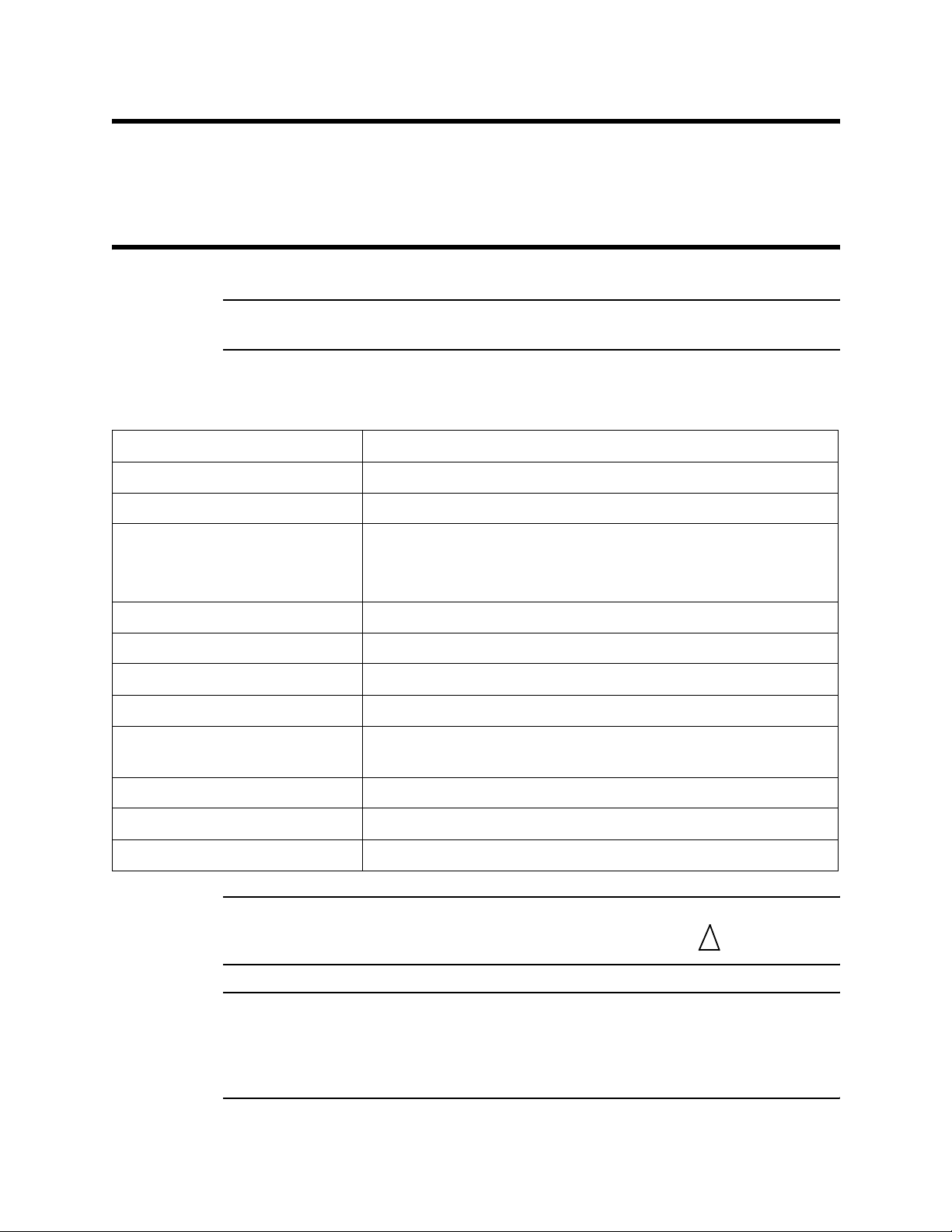
Table 1: Specifications
Target Gas Carbon Monoxide (CO)
Area Classification Explosionproof for Class I, Groups B, C, and D
Temperature Code T6
Installation Category Installation Category 1. Signal level, special equipm ent or parts of
Input Voltage 11 VDC - 30 VDC
Sampling Method Diffusion
Signal Output 4 to 20 mA
Detection Range 0 to 300 PPM (parts per million)
CO Detector Signal Output 0.3 mA at 0 ppm CO nominal
Response Time 90% in 30 seconds
Accuracy ± 5% of reading or ± 5 ppm CO (whichever is greater)
Operating Temperature 23°F to 104°F (-5°C to 40 °C)
NOTE: The following symbol on the detector label is a caution to the user to refer to this
documentation for installation and operation instructions :
equipment, telecommunication, electronic, etc., with smaller
transient overvoltages than Installati on Category (Overvoltage
Category) II (ref. IEC 664).
2.5 mA at 300 ppm CO nominal
WARNING: When using the 65-2432RK-05, you must follow the instructions and
warnings in this manual to assure proper and safe opera tion of the
65-2432RK-05 and to minimize the risk of personal injury. Be sure to
maintain and periodically calibrate the 65-2432RK-05 as described in this
manual.
65-2432RK -05 CO T ran smit ter • 1
Page 6
Description
g
I
D
Potentiometer
Potentiometer
Potentiometer
nstalled On Toxic
Select Header
etector Terminal
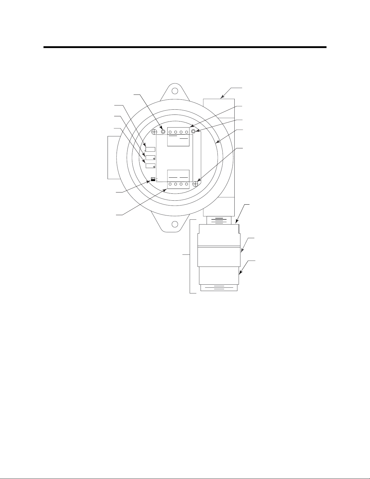
This section describes the components of the CO transmitter. The transmitter consists of
the CO detector, amplifier, and junction box.
3/4" NPT Conduit Openin
Test Point (-)
Factory Set
Zero
Span
Jumper Block
Strip
ZERO
SPAN
OXYGEN
TOXIC
TP
-
FB
Not
Used
4/20
POWER/SIG
SENSOR
TOXIC
RD BK
W
OXY
+
TP
+
24V
G
For Wire Entry
Interconnect Terminal
Strip
Test Point (+)
Amplifier
Securing Screw (2X)
Detector
Housing
Detector Housing
Cap
Carbon Monoxide
Detector
Flame Arrestor
Guard
Figure 1: CO Transmitter Component Location
CO Detector
The CO detector includes the detector housing and sensor.
Detector Housing
The detector housing protects the sensing components within the housing. Use the
mounting threads at the top of the housi ng to screw the CO detector into the bottom
conduit hub of the junction box. Use the removable cap near the bottom of the housing to
access the sensor for maintenance or replacement. The cap protects the sensor from
damage and includes a flame arrestor which contains any sparks wh ich may occur wit hin
the detector housing. A cap gasket seals the interface between the housing and cap. A
flame arrestor guard is permanently bonded to the cap.
Two wires extend from the top of the detector housing. Use these wires to connect the CO
detector to the amplifier. The housing includes a four-socket pattern. This socket pattern
accepts the sensor’s four pins to secure the sensor within the detector housing. A preamplifier , located between the sockets a nd two int erconnect wires, con dit io ns t he se nsor’s
signal before the signal reaches the amplifier.
2 • 65-2432RK-05 CO Transmit ter
Page 7

Sensor
The sensor is secured within the sensor housing by the four pins. Through a series of
chemical and electrical reactions, the sensor produces an electrical output that is
proportional to the detector range of the transmitter.
Charcoal Filter
The disc-shaped charcoal filter is secured to face of the CO sensor with a rubber boot. The
charcoal filter prevents interference gases (hydrogen sulfide [H
S] and certain
2
hydrocarbons) from producing false CO readings.
Amplifier
The amplifier converts t he electrical output from the sensor to a 4 to 20 mA signal (that is
proportional to the detection range) and transmits the signal to a gas monitoring
controller. The amplifier includes the amplifier type selector, detector terminal strip,
interconnect terminal strip, span pot, zero pot, and test points (see Figure 1).
Amplifier Type Selector
The amplifier type selector is near the bottom left corner of the amplifier. It is to the left of
the detector terminal strip and below the span pot.
The amplifier included with the CO transmitter is designed for use with RKI’s toxic gas
and oxygen transmitters. The amplifier type selector determin es fo r wh ich tran sm it te r th e
amplifier is intended. For CO transmitters, a jumper block is installed over the TOXIC
selector (see Figure 1).
Detector Terminal Strip
The detector terminal strip is the four-point terminal strip near the bottom of the
amplifier. U se the detector terminal strip to connect the CO detector to the amplifier.
NOTE: The CO detector is factory-wired to the amplifier. See the Installation section of
this manual for all wiring procedures related to the transmitter.
Interconnect Terminal Strip
The interconnect terminal strip is the four-point terminal strip near the to p of the
amplifier. Use the interconnect terminal strip to connect the amplifier to a controller.
Span Pot
The span pot is on the left side of the amplifier. Of the three potentiometers, the span pot
is bottom most. Use the span pot to adjust the transmitter’s response output during the
calibration procedure.
Zero Pot
The zero pot is above the span pot. Use the zero pot to adjust the transmitter’s target gasfree output during the start-up and calibration procedures.
CAUTION: The third potentiometer is factory-set. Do not adjust it.
Test Points
The test points (labeled TP- and TP+) are on the left and right side of the interconnect
terminal strip. The test points produce a 100 to 500 mV output that is proportional to the
transmitter’s 4 to 20 mA output. Use the test points and a voltme ter to mea sure the
65-2432RK -05 CO T ran smit ter • 3
Page 8

Installation
1
g
transmitter’s output during the start-up and calibration procedures.
Junction Box
Use the junction box to install the CO transmitter at a mounting site that is remote from
the controller. The junction box also protects the amplifier and wiring connections made
to the amplifier. Use the two 3/4 in. conduit hubs to mount the detector to the junction
box (bottom hub) and connect wiring from the amplifier to the controller (top hub).
NOTE: The CO detector and amplifier are factory-mounted to the junction box.
Use the junction box’s two mounting holes to mount the CO transmitter to a vertical
surface at the monitoring site. Use the cover on the front of the junction box to access the
interior of the junct ion box.
This section describes procedures to mount the CO transmitter in the monitoring
environment and wire the transmitter to a controller.
Mounting the CO Transmitter
1. Select a mounting site that is representative of the monitoring environment. Consider
the following when you select the mounting site.
• Select a site where the transmitter is not likely to be bumped or disturbed. Make
sure there is sufficient room to perform start-up, maintenance, and calibration
procedures.
• Select a site where the target gas is likely to be found first.
NOTE: If your application does not require a specific mounting site, mo unt the
transmitter at approximately breathing level.
.25 Dia. Mountin
Hole, 2X
3/4 NPT
Conduit Hub
8.5 max
6.10
3.94
5.46
5.20
2.75
1 1/2-20 For
Calibration Cup
.10
3.2
max
Figure 2: Mounting the CO Transmitter
4 • 65-2432RK-05 CO Transmit ter
Page 9

If the CO detector is mounted to the junction box, skip to step 5. If not, continue with
step 2.
NOTE: The CO detector is normally provided with a Killark HK B junction and an HFC
lid rated explosion proof for Class I, Groups B, C, and D. This combination is
shown in Figure 2 above. Any junction box with an internal volume less than or
equal to 69 cubic inches and rated explosion proof for ClassI, Groups B, C, and D
may be used.
2. Remove the junction box cover.
3. Guide the two wires that extend from the top of the CO detector through the bottom
conduit hub of the junction box.
4. Screw the CO detector into the bottom conduit hub of the junction box.
5. At the monitoring site, use #10 screws through the junction box’s two mounting holes
to secure the junction box to a vertical surface.
CAUTION: Mount the CO transmitter with the detector facing do wn (see Figure 2).
Wiring the CO Transmitter to a Controller
WARN ING: Always verify that the power source is OFF bef ore you make wiring
connections.
1. Turn off the controller.
2. Turn off or unplug incoming power to the controller.
3. Remove the junction box cover.
4. Verify that the detector leads are wired to the amplifier’s detector terminal strip.
If necessary, connect the detector leads to the detector terminal strip as shown in
Figure 3.
5. Verify that the jumper block is installed over the TOXIC selector of the amplifier ty p e
selector as shown in Figure 3.
6. Guide a two-conductor, shielded cable or two wires in conduit through the top
conduit hub of the junction box.
WARNING: To maintain the explosion proof classification of the CO detector/junction
box combination, a conduit seal must be used within 18 inches of the
junction box conduit hub used for wir ing to the controller.
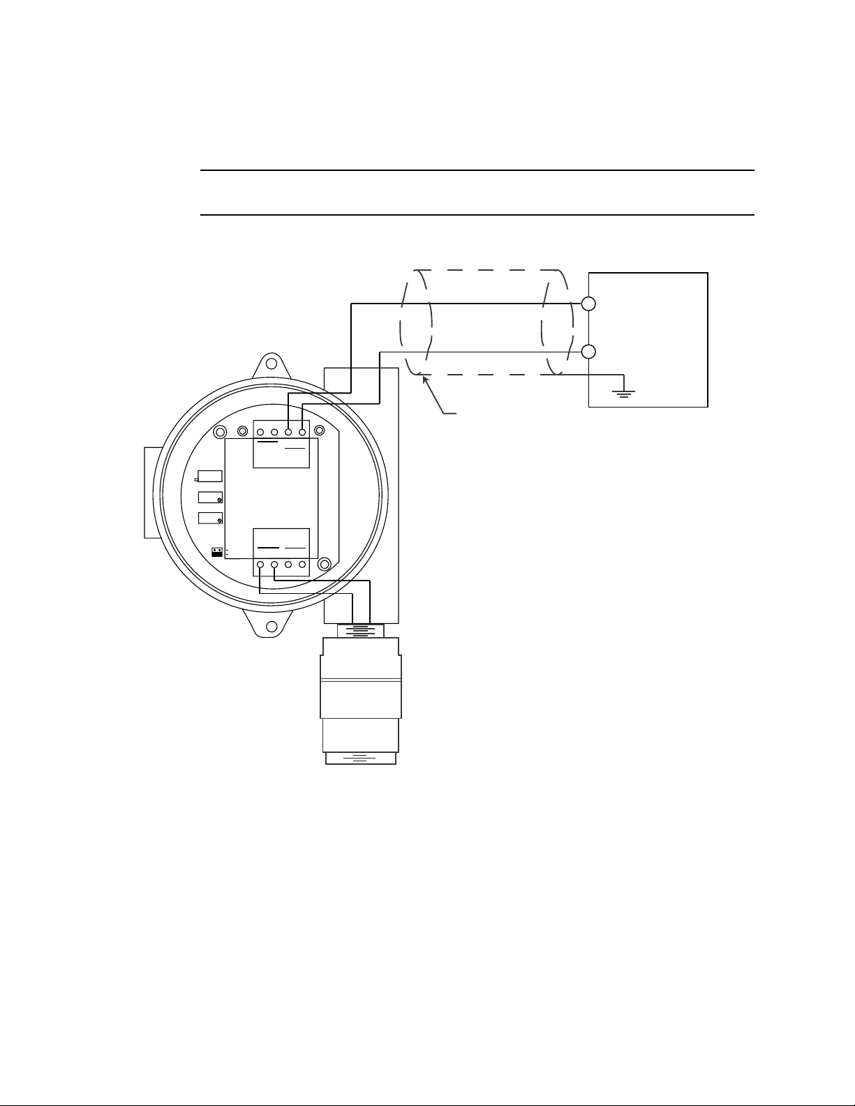
7. Connect the two wires to the interconnect terminal strip as follows (see Figure 3).
• Connect the positive wire to the terminal labeled 24V +.
• Connect the feedback wire to the terminal labeled 4/20 FB.
CAUTION: If using shielded cable, leave the drain wire insulated and disconne cted at the
transmitter. You will connect the opposite end of the cable’s drain wire at the
controller.
65-2432RK -05 CO T ran smit ter • 5
Page 10
8. Secure the junction box cover to the junction box.
er
9. Route the cable or wires leading from the CO transmitter through one of the conduit
hubs at the controller housing.
CAUTION: Do not route power and transmitter wiring through the same conduit hub. The
power cable may disrupt the transmission of the tran smitter signal to t he controller.
10. Connect the wires to the to the applicable controller transmitter terminal strip as
shown in Figure 3.
4 - 20 mA In
(FB or S)
+ 24 VDC
Cable Shield
Controller Transmitt
FB
+
4/20
TP
+
24V
OXY
W
G
Black
Red
Terminals,Typical
ZERO
SPAN
OXYGEN
TOXIC
TP
-
Not
Used
POWER/SIG
SENSOR
TOXIC
RD BK
Figure 3: Wiring the CO Transmitter to a Controller
11. If shielded cable is used, connect the cable’s drain wire to an available chassis (earth)
ground at the controller. RKI controllers typically have a ground stud that can be used
to ground the cable’s drain wire.
6 • 65-2432RK-05 CO Transmit ter
Page 11

Start Up
This section describes procedures to start up the CO transmitter and place the transmitter
into normal operation.
Introducing Incoming Power
1. Complete the installation procedures described earlier in this manual.
2. Verify that the power wiring to the controller is correct and secure. Refer to the
controller instruction manual.
3. Turn on or plug in the incoming power at the power source end, then turn on the
controller.
4. Verify that the controller is on and operating properly. Refer to the controller
instruction manual.
CAUTION: Allow the transmitter to warm up for 5 minutes before you continue with the next
section, “Setting the Zero Signal”.
Setting the Zero Signal
WARNING: Do not remove the sensor cap or junction box cover while the circuits are
energized unless the area is determined to be non-hazardous. Keep the
sensor cap and junction box cover tightly closed during operation.
NOTE: If you can verify that the detector is in a fresh air environment (environment
known to be of normal oxygen content and free of toxic and combustible gases),
it is not necessary to apply zero air when verifying or setting the fresh air
reading.
The procedure below describes applying zero emission air, usually called zero air , using a
calibration kit that includes a calibration cup, calibration gas, sample tubing, and a fixed
flow regulator with an on/off knob. RKI Instruments, Inc. recommends using a 0.5 LPM
(liters per minute) fixed flow regulator.
1. Unscrew and remove the junction box cover from the junction box.
2. Set a voltmeter to measure in the millivolt (mV) range.
3. Plug the voltmeter leads into the test points on the amplifier. Plug the positive lead
into the test point labeled TP+; plug the ne gative lead into the test point labeled TP-.
4. Screw the calibration cup onto the bottom of the detector.
5. Screw the regulator into the zero air calibration cylinder.
6. Use the sample tubing to connect the regulator to the calibration cup.
7. Turn the regulator’s on/off knob counterclockwise to open it. Gas will begin to flow.
8. Allow the gas to flow for 2 minutes.
9. Veri fy a voltmeter reading of 100 mV (±2 mV).
10. If necessary, use a flat-blade screwdriver to adjust the span pot until the voltmeter
reading is 100 mV (±2 mV).
11. Turn the regulator’s on/off knob clockwise to close it.
65-2432RK -05 CO T ran smit ter • 7
Page 12

12. Unscrew the calibration cup from the detector.
13. Unscrew the regulator from the zero air calibration cylinder. For convenience, leave
14. Store the components of the calibration kit in a safe and co nvenient place.
15. Remove the voltmeter leads from the test points.
16. Secure the junction box cover to the junction box.
Maintenance
This section describes maintenance procedures. It includes preventive maintenance,
troubleshooting, and component replacement procedures.
Preventive Maintenance
This section describes a preventive maintenance schedule to ensure the optimum
performance of the CO transmitter. It includes daily, monthly, and quarterly procedures.
Daily
Verify a display reading of 0 PPM CO at the controller. Investigate significant changes in
the display reading.
the sample tubing connected to the regulator and the calibration cup.
Monthly
This procedure describes a test to verify that the CO transmitter responds properly to
carbon monoxide. It describes the test using a calibration kit that includes a ca libration
cup, calibration gas, sample tubing, and a fixed flow regulator with an on/off knob. RKI
Instruments, Inc. recommends using a 0.5 LPM (liters per minute) fixed flow regulator.
NOTE: Performing a response test on the CO transmitter may cause alarms. Be sure to
put the controller into its calibration program or disable external alarms before
performing this test.
Preparing for the response test
1. Place the controller into its calibration program or disable external alarms.
2. Verify that the controller display reading for the channel you are testing is 0.
If the display reading is not zero, set the zero reading of the transmitter as described
in the Start Up section of this manual, then continue this procedure.
3. Screw the calibration cup onto the bottom of the CO detector.
4. Screw the regulator into the calibration cylinder.
5. Use the sample tubing to connect the regulator to the calibration cup.
6. Set a voltmeter to measure in the millivolt (mV) range.
WARNING: Do not remove the sensor cap or junction box cover while the circuits are
energized unless the area is determined to be non-hazardous. Keep the
sensor cap and junction box cover tightly closed during operation.
7. Remove the junction box cover, then plug the voltmeter leads into the test points on
the amplifier.
Plug the positive lead into the test point labeled TP+; plug the negative lead into the
8 • 65-2432RK-05 CO Transmit ter
Page 13

test point labeled TP-.
8. Use the following formula to determine the correct test points output for the test
sample.
Output (mV) = (calibrating sample/fullscale) X 400 + 100
For example, with a test sample of 50 PPM CO and a fullscale setting of
300 PPM, the correct output is 167 mV.
167 (mV) = (50/300) X 400 +100
Performing the response test
1. Turn the regulator on/off knob counterclockwise to open it. The sample will begin to
flow.
2. Allow the gas to flow for two minutes, then verify that the reading is within ± 20% of
the response reading you determined earlier.
NOTE: If the readings are not within ± 20% of the correct response reading, calibrate the
affected transmitter(s) as described in the Calibrat ion section of this manual.
3. Turn the regulator on/off knob clockwise to close it.
4. Unscrew the regulator from the calibration cylind er.
5. Unscrew the calibration cup from the CO detector.
6. Remove the voltmeter leads from the amplifier test points.
7. Reinstall the junction box cover.
8. When the controller display reading falls below th e alarm setpoints, return the
controller to normal operation.
Quarterly
Calibrate the CO transmitter as described in the Calibration section of this manual.
Troubleshooting
The troubleshooting guide describes symptoms, probable causes, and recommended
action for problems you may encounter with the CO transmitter.
NOTE: This troubleshooting guide describes transmitter problems only. See the
controller operator’s manual for problems you may encounter with the
controller.
Fail Condition
Symptoms
• The controller indicates a fail condition.
Probable causes
• The transmitter wiring is disconnecte d or misconnected.
• The transmitter’s zero reading is low enough to cause a fail condition.
• The transmitter is malfunctioning.
Recommended action
• Verify that the transmitter wiring is correct and secure.
65-2432RK -05 CO T ran smit ter • 9
Page 14

• Calibrate the transmitter.
• If the fail condition continues, replace the CO sensor.
• If the fail condition continues, contact RKI for further instruction.
Slow or No Response/Difficult or Unable to Calibrate
Symptoms
• The transmitter respon ds slowly or does not respond during the monthly response
test.
• Unable to accurately set the zero or response reading during the calibration
procedure.
• The tra nsmitte r requires frequent calibration.
NOTE: Under “normal” circumstances, the transmitter requires calibration once every
three months. Some applications may require a more frequent calibration
schedule.
Probable causes
• The calibration cylinder is low, out-dated, or defective.
• The transmitter is malfunctioning.
Recommended action
1. Verify that the calibration cyl inder con t ai ns an ade qu at e suppl y of a fresh test sampl e.
2. If the calibration/response difficulties continue, replace the CO sensor as described
later in this section.
3. If the calibration/response difficultie s continue, contact RKI Instruments, Inc. , for
further instruction.
Replacing Components of the CO Transmitter
This section includes procedure to replace the CO sensor and amplifier. A procedure to
replace the entire detector assembly is at the end of this section. In most cases, it is not
necessary to replace the entire detector assem bly.
Replacing the Sensor
CAUTION: The sensor contains electrolyte which is a dilute acid. Do not dis assemble the sens o r
when replacing it with a new one. If sensor electrolyte comes in co ntact with your
skin, wash affected area thoroughly with soap and water.
1. Turn off the controller.
2. Turn off or unplug incoming power to the controller.
3. Unscrew the bottom section of the CO detector housing from the top section.
4. Unplug and remove the CO sensor with the boot and charcoal filter attached.
5. Remove the rubber boot and charcoal filter from old sensor.
6. Install the rubber boot with charcoal filter onto the replacement sensor’s face.
7. Carefully plug the replacement sensor into the socket pattern that is located in the top
section of the detector housing.
10 • 65-2432RK-05 CO Transmit ter
Page 15

NOTE: Match the sensor’s male pins with the four female sockets as you plug the sensor
into the socket.
8. Screw the bottom section of the detector housing onto the top section.
9. Turn on or plug in incoming power to the controller.
10. Turn on the controller.
CAUTION: Allow the r ep la cem ent sens or to w arm up for 5 m inu tes before you continue with the
next step.
11. Calibrate the replacement sensor as described in the Calibration section of this
manual.
Replacing the Charcoal Filter
1. Turn off the controller.
2. Turn off or unplug incoming power at the power source end.
3. Unscrew the bottom section of the CO detector housing from the top section.
4. Unplug and remove the CO sensor with the boot and charcoal filter attached.
5. Remove the rubber boot that secures the charcoal filter to the CO sensor.
6. Remove the charcoal filter from the rubber boot.
7. Place the replacement filter in the rubber boot in the same position as the filter you
removed in the previous step.
8. Reinstall the rubber boot with charcoal filter to the CO sensor.
9. Carefully plug the replacement sensor into the socket pattern that is located in the top
section of the detector housing.
NOTE: Match the sensor’s male pins with the four female sockets as you plug the sensor
into the sockets.
10. Screw the bottom section of the detector housing onto the top section.
11. Turn on or plug in incoming power at the power source end.
12. Turn on the controller.
Replacing the Amplifier
1. Turn off the controller.
2. Turn off or unplug incoming power to the controller.
3. Remove the junction box cover.
4. Disconnect the detector leads from the detector terminal strip.
5. Unscrew and remove the two screws that secure the amplifier to the junction box.
The screws are at the top left and bottom right of the amplifier.
6. Remove the amplifier.
7. Place the new amplifier in the same position as the old amplifier.
8. Use the two screws you removed in step 5 to secure the new amplifier to the junction
box.
65-2432RK-05 CO Tr an s mi t te r • 1 1
Page 16

9. Verify that the jumper block is installed over the TOXIC selector of the amplifier ty p e
selector as shown in Figure 3.
10. Reconnect the wiring from the controller to the interconnect terminal strip as shown
in Table 2 and Figure 3.
Table 2: Reconnecting the CO Amplifier to a Controller
Amplifier
Interconnect Terminal
Strip
Controller Transmitter
Terminal Strip (typical)
4/20 FB 4 -20 (FB)
24V + + V (11 - 30 VDC)
11. Reconnect the detector leads to the detector terminal strip as shown in Table 3 and
Figure 3.
Table 3: Reconnecting the CO Detector to the Amplifier
Amplifier
CO Detector Lead
Interconnect Terminal
Strip
Black TOXIC BK
Red TOXIC RD
12. Reinstall the junction box cover.
13. Turn on or plug in incoming power at the power source end.
14. Turn on the controller.
CAUTION: Allow the sensor to warm up for 5 minutes be fore you continue with the next step.
15. Calibrate the CO transmitter as described in the Calibration section of this manual.
Replacing the CO Detector
NOTE: In most cases, it is only necessary to replace the CO sensor.
1. Turn off the controller.
2. Turn off or unplug incoming power at the power source end.
3. Remove the junction box cover.
4. Disconnect the detector leads from the detector terminal strip. Note the position of the
color-coded leads as you remove them.
5. Unscrew the detector from the junction box.
6. Guide the detector leads of the replacement detector through the bottom conduit hub
of the junction box, then screw the mounting threads of the detector into the conduit
hub.
12 • 65-2432RK-05 CO Transmit ter
Page 17

7. Connect the detector leads to the detector terminal strip as shown in Table 4 and
Figure 3.
Table 4: Connecting the Replacement CO Detector to the Amplifier
Amplifier
CO Detector Lead
Black TOXIC BK
Red TOXIC RD
8. Reinstall the junction box cover.
9. Turn on or plug in incoming power to the controller.
10. Turn on the controller.
CAUTION: Allow the replacement detector to warm up for 5 minutes before y o u c o ntinue with
the next step.
11. Calibrate the replacement detector as described in the Calibration section of this
manual.
12. Secure the junction box cover to the junction box.
Interconnect Terminal
Strip
Calibration Frequency
Although there is no particular calibration frequency that is correct for all applications, a
calibration frequency of every 3 to 6 months is adequate for most CO transmitter
applications. Unless experience in a particular application dictates otherwise, RKI
Instruments, Inc. recommends a calibration frequency of every 3 months.
If an application is not very demanding, for example detection in a clean, temperature
controlled environment where CO is not normally present and calibration adjustments are
minimal at calibration, then a calibration frequency of every 6 months is adequate.
If an application is very demanding, for example if CO is present often and in significant
concentrations or the environment is not well controlled, then more frequen t calibration
than every 3 months may be necessary.
65-2432RK-05 CO Tr an s mi t te r • 1 3
Page 18

Calibration
This section describes how to calibrate the CO transmitter. It includes procedures to
prepare for calibration, set the zero reading, set the response rea d ing, and return to
normal operation. It describes th e te st using a calibration kit that includes a calibration
cup, calibration gas, sample tubing, and a fixed flow regulator with an on/off knob. RKI
Instruments, Inc. recommends using a 0.5 LPM (liters per minute) fixed flow regulator.
Prepari ng for Ca libration
NOTE: Calibrating the CO transmitter may cause alarms. Be sure to put the controller
into its calibration program or disable external alarms before calibrating.
1. Screw the calibration cup onto the bottom of the CO detector.
2. Screw the regulator into the zero air calibration cylinder.
3. Use the sample tubing to connect the fixed flow regulator to the calibration cup.
4. Set a voltmeter to measure in the millivolt (mV) range.
WARNING: Do not remove the sensor cap or junction box cover while the circuits are
energized unless the area is determined to be non-hazardous. Keep the
sensor cap and junction box cover tightly closed during operation.
5. Remove the junction box cover, then plug the voltmeter leads into the test points on
the amplifier.
Plug the positive lead into the test point labeled TP+; plug the negative lead into the
test point labeled TP-.
6. Use the following formula to determine the correct test points output for the
calibrating sample.
Output (mV) = (calibrating sample/fullscale) X 400 + 100
For example, with a calibrating sample of 50 PPM CO and a fullscale setting of
300 PPM, the correct output is 167 mV.
167 (mV) = (50/300) X 400 +100
Setting the Zero Reading
NOTE If you can verify that the CO transmitter is in a fresh air environment, you do not
need to apply zero air to the detector before adjusting the zero reading.
1. Turn the regulator on/off knob counterclockwise to open it.
2. Allow the gas to flow for two minutes.
3. Verify a reading of 100 mV (± 2mV).
4. If necessary, use the zero pot on the amplifier to adjust the reading to 100 mV (± 2mV).
5. Turn the regulator on/off knob clockwise to close it.
6. Unscrew the regulator from the zero air calibration cylinder.
Leave the sample tubing connected to the regulator and the calibration cup.
14 • 65-2432RK-05 CO Transmit ter
Page 19

Setting the Response Reading
1. Screw the regulator into the calibration cylinder. Verify that the calibration gas is
representative of the transmitter’s target gas.
2. Turn the regulator on/off knob counterclockwise to open it.
3. Allow the gas to flow for two minutes.
4. Verify that the reading matches the response reading (± 2mV) you determined earlier.
5. If necessary, use the span pot on the amplifier to adjust the reading to match the
correct response reading.
6. Turn the regulator on/off knob clockwise to close it.
7. Unscrew the regulator from the calibration cylind er.
8. Unscrew the calibration cup from the detector.
NOTE: For convenience, leave the components of the calibration kit connected by the
sample tubing.
Returning to Normal Operation
1. Remove the voltmeter leads from the amplifier test points.
2. Secure the junction box cover to the junction box.
3. When the display reading falls below the ala r m setpoints, return the controller to
normal operation.
4. Verify that the controller display reading decreases and stabilizes at 0 ppm.
5. Store the components of the calibration kit in a safe and convenient place.
65-2432RK-05 CO Tr an s mi t te r • 1 5
Page 20

Parts List
Table 5 lists replacement parts and accessories for the CO transmitter.
Table 5: Parts List
Part Number Description
06-1248RK Sample tubing (order by the foot)
07-0033RK Detector housing cap gasket
07-0203RK Rubber retaining boot (for cha rcoal filter)
18-0405RK-01 Junction box (without cover; pre drilled for amplifier)
18-0406RK Junction box cover
33-7101RK Charcoal Filter Disk
57-1060RK Amplifier (specify ta rget gas when ordering)
65-2432RK-05 CO transmitter (includes detector and amplifier), CSA classified
65-2433RK-05 CO replacement detector assembly (includes sensor), CSA classified
71-0113RK 65-2432RK-05 CO Transmitter Operator’s Manual (this document)
81-0064RK-0 1 Calibration cylin der (50 PPM CO in ai r; 34 liter steel)
81-0076RK-01 Zero air calibration cylinder (34 liter steel)
81-1050RK Regulator with gauge and knob, 0.5 LPM, for 17 liter an d 34 liter
steel calibration cylinders
81-1117RK Calibration cup
ES-1531-CO CO replacement sensor
16 • 65-2432RK-05 CO Transmit ter
 Loading...