

Page 1

65-2432RK
Carbon Monoxide Transmitter
Operator’s Manual
Part Number: 71-0070RK
Revision: P1
Released: July 8, 2001
RKI Instruments, Inc.
1855 Whipple Road
Hayward CA 94544
Phone: 800-754-5165 Fax: 510-441-5650
Page 2

Product W arranty
RKI Instruments, Inc., warrants gas alarm equipment sold by us to be free from defects in
materials, workmanship, and performance for a period of one year from date of
shipment from RKI Instruments, Inc. Any parts found defective within that period will
be repaired or replaced, at our option, free of charge. This warranty does not apply to
those items which by their nature are subject to deterioration or consumption in normal
service, and which must be cleaned, repaired, or replaced on a routine basis. Examples of
such items are:
a) Absorbent cartridges d) Batteries
b) Pump diaphragms and valves e) Filter elements
c) Fuses
Warranty is voided by abuse including mechanical damage, alteration, rough handling,
or repair procedures not in accordance with the operator’s manual. This warranty
indicates the full extent of our liability, and we are not responsible for removal or
replacement costs, local repair costs, transportation costs, or contingent expenses incurred
without our prior approval.
THIS WARRANTY IS EXPRESSLY IN LIEU OF ANY AND ALL OTHER
WARRANTIES AND REPRESENTATIONS, EXPRESSED OR IMPLIED,
AND ALL OTHER OBLIGATIONS OR LIABILITIES ON THE PART OF
RKI INSTRUMENTS, INC., INCLUDING BUT NOT LIMITED TO, THE
WARRANTY OF MERCHANTABILITY OR FITNESS FOR A
PARTICULAR PURPOSE. IN NO EVENT SHALL RKI INSTRUMENTS,
INC., BE LIABLE FOR INDIRECT, INCIDENTAL, OR CONSEQUENTIAL
LOSS OR DAMAGE OF ANY KIND CONNECTED WITH THE USE OF
ITS PRODUCTS OR FAILURE OF ITS PRODUCTS TO FUNCTION OR
OPERATE PROPERLY.
This warranty covers instruments and parts sold to users by authorized distributors,
dealers, and representatives as appointed by RKI Instruments, Inc.
We do not assume indemnification for any accident or damage caused by the operation of
this gas monitor, and our warranty is limited to the replacement of parts or our complete
goods.
65-2432RK CO Transmitter • 2
Page 3

Table of Contents
Overview . . . . . . . . . . . . . . . . . . . . . . . . . . . . . . . . . . . . . . . . . . . . . . . . . . . . . . . . . . . . . . . . . . . 4
Specifications. . . . . . . . . . . . . . . . . . . . . . . . . . . . . . . . . . . . . . . . . . . . . . . . . . . . . . . . . . . . . . . . 4
Description. . . . . . . . . . . . . . . . . . . . . . . . . . . . . . . . . . . . . . . . . . . . . . . . . . . . . . . . . . . . . . . . . . 5
CO Detector . . . . . . . . . . . . . . . . . . . . . . . . . . . . . . . . . . . . . . . . . . . . . . . . . . . . . . . . . . . . . . . . . . . . . . . . . . 5
Amplifier . . . . . . . . . . . . . . . . . . . . . . . . . . . . . . . . . . . . . . . . . . . . . . . . . . . . . . . . . . . . . . . . . . . . . . . . . . . . 6
Junction Box. . . . . . . . . . . . . . . . . . . . . . . . . . . . . . . . . . . . . . . . . . . . . . . . . . . . . . . . . . . . . . . . . . . . . . . . . . 7
Installation . . . . . . . . . . . . . . . . . . . . . . . . . . . . . . . . . . . . . . . . . . . . . . . . . . . . . . . . . . . . . . . . . . 7
Mounting the CO Transmitter. . . . . . . . . . . . . . . . . . . . . . . . . . . . . . . . . . . . . . . . . . . . . . . . . . . . . . . . . . . 7
Wiring the CO Transmitter to a Controller . . . . . . . . . . . . . . . . . . . . . . . . . . . . . . . . . . . . . . . . . . . . . . . . 8
Startup. . . . . . . . . . . . . . . . . . . . . . . . . . . . . . . . . . . . . . . . . . . . . . . . . . . . . . . . . . . . . . . . . . . . . 10
Introducing Incoming Power . . . . . . . . . . . . . . . . . . . . . . . . . . . . . . . . . . . . . . . . . . . . . . . . . . . . . . . . . . 10
Setting the Zero Signal. . . . . . . . . . . . . . . . . . . . . . . . . . . . . . . . . . . . . . . . . . . . . . . . . . . . . . . . . . . . . . . . 10
Maintenance. . . . . . . . . . . . . . . . . . . . . . . . . . . . . . . . . . . . . . . . . . . . . . . . . . . . . . . . . . . . . . . . 11
Preventive Maintenance . . . . . . . . . . . . . . . . . . . . . . . . . . . . . . . . . . . . . . . . . . . . . . . . . . . . . . . . . . . . . . 11
Troubleshooting . . . . . . . . . . . . . . . . . . . . . . . . . . . . . . . . . . . . . . . . . . . . . . . . . . . . . . . . . . . . . . . . . . . . . 12
Replacing Components of the CO Transmitter . . . . . . . . . . . . . . . . . . . . . . . . . . . . . . . . . . . . . . . . . . . 13
Calibration . . . . . . . . . . . . . . . . . . . . . . . . . . . . . . . . . . . . . . . . . . . . . . . . . . . . . . . . . . . . . . . . . 16
Preparing for Calibration. . . . . . . . . . . . . . . . . . . . . . . . . . . . . . . . . . . . . . . . . . . . . . . . . . . . . . . . . . . . . . 16
Setting the Zero Reading . . . . . . . . . . . . . . . . . . . . . . . . . . . . . . . . . . . . . . . . . . . . . . . . . . . . . . . . . . . . . . 16
Setting the Response Reading. . . . . . . . . . . . . . . . . . . . . . . . . . . . . . . . . . . . . . . . . . . . . . . . . . . . . . . . . . 17
Returning to Normal Operation. . . . . . . . . . . . . . . . . . . . . . . . . . . . . . . . . . . . . . . . . . . . . . . . . . . . . . . . 17
Parts List . . . . . . . . . . . . . . . . . . . . . . . . . . . . . . . . . . . . . . . . . . . . . . . . . . . . . . . . . . . . . . . . . . . 18
65-2432RK CO Transmitter • 3
Page 4

Overview
This manual describes the carbon monoxide (CO) transmitter. This manual also
describes how to install, start up, maintain, and calibrate the transmitter. A parts list
at the end of this manual lists replacement parts and accessories for the CO transmitter.
Specifications
Table 1 lists specifications for the CO transmitter.
Table 1: Specifications
Target Gas Carbon Monoxide (CO)
Area Classification Explosionproof for Class I, Groups B, C, and D
Input Voltage 11 VDC - 30 VDC
Sampling Method Diffusion
Signal Output 4 to 20 mA
Detection Range 0 to 300 PPM (parts per million)
Response Time 90% in 30 seconds
65-2432RK CO Transmitter • 4
Page 5
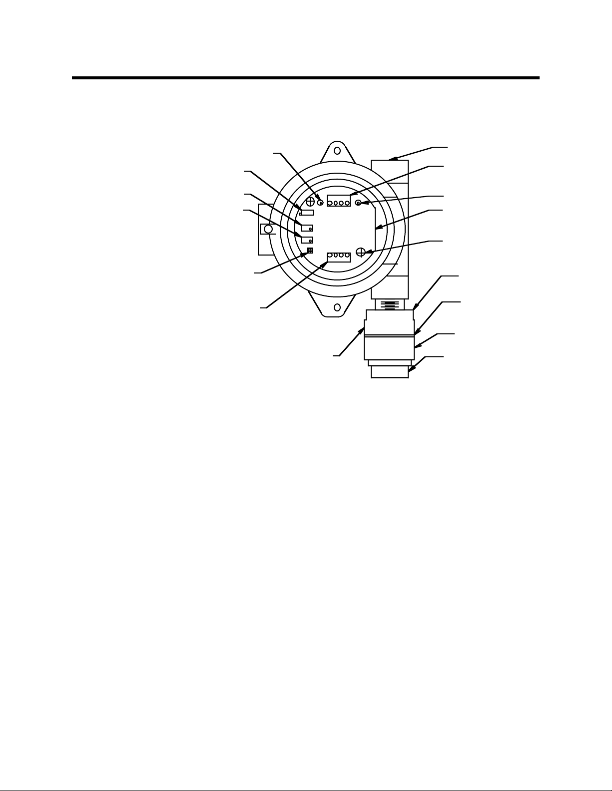
Description
This section describes the components of the CO transmitter. The transmitter consists of
the CO detector, amplifier, and junction box.
Test Point (-)
Factory Set
Potentiometer
Zero Potentiometer
Span Potentiometer
Jumper Block Installed To
Toxic Select Header
Detector Terminal Strip
Carbon Monoxide Detector
CO Detector
3/4" Conduit Hub
Interconnect Terminal
Strip
Test Point (+)
Carbon Monoxide
Amplifier
Securing Screw (2)
Detector Housing
CapGasket
Detector Housing
Cap
Flame Arrestor
Figure 1: CO Transmitter Component Location
The CO detector includes the detector housing and sensor.
Detector housing
The detector housing protects the sensing components within the housing. Use the
mounting threads at the top of the housing to screw the CO detector into the bottom
conduit hub of the junction box. Use the removable cap near the bottom of the housing to
access the sensor for maintenance or replacement. The cap protects the sensor from
damage and includes a flame arrestor which contains any sparks which may occur
within the detector housing. A cap gasket seals the interface between the housing and
cap.
Two wires extend from the top of the detector housing. Use these wires to connect the CO
detector to the amplifier. The housing includes a four-socket pattern. This socket
pattern accepts the sensor’s four pins to secure the sensor within the detector housing. A
pre-amplifier, located between the sockets and two interconnect wires, conditions the
sensor’s signal before the signal reaches the amplifier.
Sensor
The sensor is secured within the sensor housing by the four pins. Through a series of
chemical and electrical reactions, the sensor produces an electrical output that is
proportional to the detector range of the transmitter.
65-2432RK CO Transmitter • 5
Page 6

Charcoal Filter
The disc-shaped charcoal filter is secured to face of the CO sensor with a rubber boot.
The charcoal filter prevents interference gases (hydrogen sulfide [H
S] and certain
2
hydrocarbons) from producing false CO readings.
Amplifier
The amplifier converts the electrical output from the sensor to a 4 to 20 mA signal (that
is proportional to the detection range) and transmits the signal to a gas monitoring
controller. The amplifier includes the amplifier type selector, detector terminal strip,
interconnect terminal strip, span potentiometer, zero potentiometer, and test points (see
Figure 1.)
Amplifier type selector
The amplifier type selector is near the bottom left corner of the amplifier. It is to the
left of the detector terminal strip and below the span potentiometer.
The amplifier included with the CO transmitter is designed for use with RKI’s toxic gas
and oxygen transmitters. The amplifier type selector determines for which transmitter
the amplifier is intended. For CO transmitters, a jumper block is installed over the
TOXIC selector (see Figure 1.)
Detector terminal strip
The detector terminal strip is the four-point terminal strip near the bottom of the
amplifier. Use the detector terminal strip to connect the CO detector to the amplifier.
NOTE: The CO detector is factory-wired to the amplifier. See the Installation section
of this manual for all wiring procedures related to the transmitter.
Interconnect terminal strip
The interconnect terminal strip is the four-point terminal strip near the top of the
amplifier. Use the interconnect terminal strip to connect the amplifier to a controller.
Span potentiometer
The span potentiometer is on the left side of the amplifier. Of the three potentiometers,
the span potentiometer is bottom most. Use the span potentiometer to adjust the
transmitter’s response output during the calibration procedure.
Zero potentiometer
The zero potentiometer is above the span potentiometer. Use the zero potentiometer to
adjust the transmitter’s target gas-free output during the start-up and calibration
procedures.
CAUTION: The third potentiometer is factory-set. Do not adjust it.
Test points
The test points (labeled TP- and TP+ ) are on the left and right side of the interconnect
terminal strip. The test points produce a 100 to 500 mV output that is proportional to the
transmitter’s 4 to 20 mA output. Use the test points and a voltmeter to measure the
transmitter’s output during the start-up and calibration procedures.
65-2432RK CO Transmitter • 6
Page 7

Installation
Junction Box
Use the junction box to install the CO transmitter at a mounting site that is remote from
the controller. The junction box also protects the amplifier and wiring connections made
to the amplifier. Use the two 3/4 in. conduit hubs to mount the detector to the junction
box (bottom hub) and connect wiring from the amplifier to the controller (top hub).
NOTE: The CO detector and amplifier are factory-mounted to the junction box.
Use the junction box’s two mounting holes to mount the CO transmitter to a vertical
surface at the monitoring site. Use the cover on the front of the junction box to access the
interior of the junction box.
This section describes procedures to mount the CO transmitter in the monitoring
environment and wire the transmitter to a controller.
Mounting the CO Transmitter
1. Select a mounting site that is representative of the monitoring environment.
Consider the following when you select the mounting site.
• Select a site where the transmitter is not likely to be bumped or disturbed. Make
sure there is sufficient room to perform start-up, maintenance, and calibration
procedures.
• Select a site where the target gas is likely to be found first.
NOTE: If your application does not require a specific mounting site, mount the
transmitter at approximately breathing level.
6.1
3.94
5.2
2.75
5.46
Ø .25 Mouting Holes (2X)
3/4 Conduit Hub
8.3 max
1.1
2.85 max
Figure 2: Mounting the CO Transmitter
65-2432RK CO Transmitter • 7
Page 8

If the CO detector is mounted to the junction box, skip to step 5. If not, continue with
step 2.
2. Remove the junction box cover.
3. Guide the two wires that extend from the top of the CO detector through the bottom
conduit hub of the junction box.
4. Screw the CO detector into the bottom conduit hub of the junction box.
5. At the monitoring site, use #10 screws through the junction box’s two mounting holes
to secure the junction box to a vertical surface.
CAUTION: Mount the CO transmitter with the detector facing down (see Figure 2.)
Wiring the CO Transmitter to a Controller
WARNING: Always verify that the power source is OFF before you make wiring
connections.
1. Turn off the controller.
2. Turn off or unplug incoming power at the power source end.
3. Remove the junction box cover.
4. Verify that the detector leads are wired to the amplifier’s detector terminal strip.
If necessary, connect the detector leads to the detector terminal strip as shown in
Figure 3.
5. Verify that the jumper block is installed over the TOXIC selector of the amplifier type
selector as shown in Figure 3.
6. Guide a two-conductor, shielded cable or two wires in conduit through the top
conduit hub of the junction box.
7. Connect the two wires to the interconnect terminal strip as follows (see Figure 3.)
• Connect the positive wire to the terminal labeled 24V + .
• Connect the feedback wire to the terminal labeled 4/20 FB .
CAUTION: If using shielded cable, leave the drain wire insulated and disconnected at the
transmitter. You will connect the opposite end of the cable’s drain wire at the
controller.
8. Secure the junction box cover to the junction box.
9. Route the cable or wires leading from the CO transmitter through one of the conduit
hubs at the controller housing.
CAUTION: Do not route power and transmitter wiring through the same conduit hub. The
power cable may disrupt the transmission of the transmitter signal to the controller.
65-2432RK CO Transmitter • 8
Page 9

10. Connect the wires to the to the applicable controller transmitter terminal strip as
shown in Figure 3.
NotUsed
Factory Set Pot.
Toxics
Amplifier
ZERO
SPAN
OXY
TOXIC
TOXIC
FB
4/20 24VBATT
+ 24 VDC
OXY
BKRD
G
W
4 - 20 mA In (FB)
Jumper Block
Installed To Toxic
Select Header
Black
Red
CO Detector,
Factory Wired
Controller or
Recording Device
Figure 3: Wiring the CO Transmitter to a Controller
11. Connect the cable’s drain to an available chassis ground at the controller.
65-2432RK CO Transmitter • 9
Page 10

Start Up
This section describes procedures to start up the CO transmitter and place the
transmitter into normal operation.
Introducing Incoming Power
1. Complete the installation procedures described earlier in this manual.
2. Verify that the power wiring to the controller is correct and secure. Refer to the
controller instruction manual.
3. Turn on or plug in the incoming power at the power source end, then turn on the
controller.
4. Verify that the controller is on and operating properly. Refer to the controller
instruction manual.
CAUTION: Allow the transmitter to warm up for 5 minutes before you continue with the next
section, “Setting the Zero Signal.”
Setting the Zero Signal
CAUTION: If you suspect the presence of the target gas in the monitoring environment, use the
calibration kit and the zero air calibration cylinder to introduce “fresh air” to the
sensor and verify an accurate zero setting.
1. Verify that the transmitter is in a fresh air environment (environment known to be
free of carbon monoxide, other toxic and combustible gases and of normal oxygen
content, 20.9%).
2. Unscrew and remove the junction box cover from the junction box.
3. Set a voltmeter to measure in the millivolt (mV) range.
4. Plug the voltmeter leads into the test points on the amplifier. Plug the positive
lead into the test point labeled TP+ ; plug the negative lead into the test point
labeled TP- .
5. Verify a voltmeter reading of 100 mV (±2 mV).
6. If necessary, use a flat-blade screwdriver to adjust the zero potentiometer until the
voltmeter reading is 100 mV (±2 mV).
7. Remove the voltmeter leads and secure the junction box cover to the junction box.
65-2432RK CO Transmitter • 10
Page 11

Maintenance
This section describes maintenance procedures. It includes preventive maintenance,
troubleshooting, and component replacement procedures.
Preventive Maintenance
This section describes a preventive maintenance schedule to ensure the optimum
performance of the CO transmitter. It includes daily, monthly, and quarterly
procedures.
Daily
1. Verify a display reading of 0 PPM CO at the controller. Investigate significant
Monthly
This procedure describes a test to verify that the CO transmitter responds properly to
carbon monoxide. It describes the test using a fixed flow regulator which has no on/off
knob and allows sample to flow as soon as it is screwed into a cylinder. RKI Instruments,
Inc. recommends using a 0.5 LPM (liters per minute) fixed flow regulator
NOTE: Performing a response test on the CO transmitter may cause alarms. Be sure to
changes in the display reading.
put the controller into its calibration program or disable external alarms before
performing this test.
Preparing for the response test
1. Place the controller into its calibration program or disable external alarms.
2. Verify that the controller display reading for the channel you are testing is 0.
If the display reading is not zero, set the zero reading of the transmitter as
described in the Start Up section of this manual, then continue this procedure.
3. Screw the calibration cup onto the bottom of the CO detector.
4. Use the sample tubing to connect the regulator to the calibration cup.
NOTE: Do not screw the regulator into the calibration cylinder at this time.
5. Set a voltmeter to measure in the millivolt (mV) range.
6. Remove the junction box cover, then plug the voltmeter leads into the test points on
the amplifier.
Plug the positive lead into the test point labeled TP+ ; plug the negative lead into
the test point labeled TP- .
7. Use the following formula to determine the correct test points output for the test
sample.
Output (mV) = (calibrating sample/fullscale) X 400 + 100
For example, with a test sample of 50 PPM CO and a fullscale setting of
300 PPM, the correct output is 167 mV.
167 (mV) = (50/300) X 400 +100
65-2432RK CO Transmitter • 11
Page 12

Performing the response test
1. Screw the regulator into the calibration cylinder. The sample will begin to flow
2. Allow the gas to flow for two minutes, then verify that the reading is within ± 10%
of the response reading you determined earlier.
NOTE: If the readings are not within ± 10% of the correct response reading, calibrate
the affected transmitter(s) as described in the Calibration section of this
manual.
3. Unscrew the regulator from the calibration cylinder.
4. Unscrew the calibration cup from the CO detector.
5. Remove the voltmeter leads from the amplifier test points.
6. Reinstall the junction box cover.
7. When the controller display reading falls below the alarm setpoints, return the
controller to normal operation.
Quarterly
Calibrate the CO transmitter as described in the Calibration section of this manual.
Troubleshooting
The troubleshooting guide describes symptoms, probable causes, and recommended
action for problems you may encounter with the CO transmitter.
NOTE: This troubleshooting guide describes transmitter problems only. See the
controller instruction manual for problems you may encounter with the
controller.
Fail condition
Symptoms
• The controller indicates a fail condition.
Probable causes
• The transmitter wiring is disconnected or misconnected.
• The transmitters zero reading is low enough to cause a fail condition.
• The transmitter is malfunctioning.
Recommended action
• Verify that the transmitter wiring is correct and secure.
• Calibrate the transmitter.
• If the fail condition continues, replace the CO sensor.
• If the fail condition continues, contact RKI for further instruction.
Slow or no response/difficult or unable to calibrate
Symptoms
• The transmitter responds slowly or does not respond during the monthly response
test.
65-2432RK CO Transmitter • 12
Page 13

• Unable to accurately set the zero or response reading during the calibration
procedure.
• The transmitter requires frequent calibration.
NOTE: Under “normal” circumstances, the transmitter requires calibration once every
three months. Some applications may require a more frequent calibration
schedule.
Probable causes
• The calibration cylinder is low, out-dated, or defective.
• The transmitter is malfunctioning.
Recommended action
1. Verify that the calibration cylinder contains an adequate supply of a fresh test
sample.
2. If the calibration/response difficulties continue, replace the CO sensor as described
later in this section.
3. If the calibration/response difficulties continue, contact RKI Instruments, Inc., for
further instruction.
Replacing Components of the CO Transmitter
This section includes procedure to replace the CO sensor and amplifier. A procedure to
replace the entire detector assembly is at the end of this section. In most cases, it is not
necessary to replace the entire detector assembly.
Replacing the sensor
4. Turn off the controller.
5. Turn off or unplug incoming power at the power source end.
6. Unscrew the bottom section of the CO detector housing from the top section.
7. Unplug and remove the CO sensor with the boot and charcoal filter attached
8. Remove the rubber boot and charcoal filter from old sensor.
9. Install the rubber boot with charcoal filter onto the replacement sensor’s face.
10. Carefully plug the replacement sensor into the socket pattern that is located in the top
section of the detector housing.
NOTE: Match the sensor’s male pins with the four female sockets as you plug the sensor
into the socket.
11. Screw the bottom section of the detector housing onto the top section.
12. Turn on or plug in incoming power at the power source end.
13. Turn on the controller.
CAUTION: Allow the replacement sensor to warm up for 5 minutes before you continue with the
next step.
14. Calibrate the replacement sensor as described in the Calibration section of this
manual.
65-2432RK CO Transmitter • 13
Page 14

Replacing the charcoal filter
1. Turn off the controller.
2. Turn off or unplug incoming power at the power source end.
3. Unscrew the bottom section of the CO detector housing from the top section.
4. Unplug and remove the CO sensor with the boot and charcoal filter attached
5. Remove the rubber boot that secures the charcoal filter to the CO sensor.
6. Remove the charcoal filter from the rubber boot.
7. Place the replacement filter in the rubber boot in the same position as the filter you
removed in the previous step.
8. Reinstall the rubber boot with charcoal filter to the CO sensor.
9. Carefully plug the replacement sensor into the socket pattern that is located in the top
section of the detector housing..
NOTE: Match the sensor’s male pins with the four female sockets as you plug the sensor
into the sockets.
10. Screw the bottom section of the detector housing onto the top section.
11. Turn on or plug in incoming power at the power source end.
12. Turn on the controller.
Replacing the amplifier
1. Turn off the controller.
2. Turn off or unplug incoming power at the power source end.
3. Remove the junction box cover.
4. Disconnect the detector leads from the detector terminal strip.
5. Unscrew and remove the two screws that secure the amplifier to the junction box.
The screws are at the top left and bottom right of the amplifier.
6. Remove the amplifier.
7. Place the new amplifier in the same position as the old amplifier.
8. Use the two screws you removed in step 5 to secure the new amplifier to the junction
box.
9. Verify that the jumper block is installed over the TOXIC selector of the amplifier
type selector as shown in Figure 3, Wiring the CO Transmitter to a Controller.
10. Reconnect the wiring from the controller to the interconnect terminal strip as shown
in Table 2 and Figure 3, Wiring the CO Transmitter to a Controller.
Table 2: Reconnecting the CO Amplifier to a Controller
Amplifier
Interconnect Terminal
Strip
Controller Transmitter
Terminal Strip (typical)
65-2432RK CO Transmitter • 14
4/20 FB 4 -20 (FB)
24V + + V (11 - 30 VDC)
Page 15

11. Reconnect the detector leads to the detector terminal strip as shown in Table 3 and
Figure 3, Wiring the CO Transmitter to a Controller.
Table 3: Reconnecting the CO Detector to the Amplifier
Amplifier
CO Detector Lead
Interconnect Terminal
Strip
Black TOXIC BK
Red TOXIC RD
12. Reinstall the junction box cover.
13. Turn on or plug in incoming power at the power source end.
14. Turn on the controller.
CAUTION: Allow the sensor to warm up for 5 minutes before you continue with the next step.
15. Calibrate the CO transmitter as described in the Calibration section of this manual.
Replacing the CO detector
NOTE: In most cases, it is only necessary to replace the CO sensor.
1. Turn off the controller.
2. Turn off or unplug incoming power at the power source end.
3. Remove the junction box cover.
4. Disconnect the detector leads from the detector terminal strip. Note the position of
the color-coded leads as you remove them.
5. Unscrew the detector from the junction box.
6. Guide the detector leads of the replacement detector through the bottom conduit
hub of the junction box, then screw the mounting threads of the detector into the
conduit hub.
7. Connect the detector leads to the detector terminal strip as shown in Table 4 and
Figure 3, Wiring the CO Transmitter to a Controller.
Table 4: Connecting the Replacement CO Detector to the Amplifier
Amplifier
CO Detector Lead
Interconnect Terminal
Strip
Black TOXIC BK
Red TOXIC RD
8. Reinstall the junction box cover.
9. Turn on or plug in incoming power at the power source end.
10. Turn on the controller.
65-2432RK CO Transmitter • 15
Page 16

Calibration
CAUTION: Allow the replacement detector to warm up for 5 minutes before you continue with
the next step.
11. Calibrate the replacement detector as described in the Calibration section of this
manual.
12. Secure the junction box cover to the junction box.
This section describes how to calibrate the CO transmitter. It includes procedures to
prepare for calibration, set the zero reading, set the response reading, and return to
normal operation. It describes calibration using a fixed flow regulator which has no on/
off knob and allows sample to flow as soon as it is screwed into a cylinder. RKI
Instruments, Inc. recommends using a 0.5 LPM (liters per minute) fixed flow regulator.
Preparing for Calibration
1. Screw the calibration cup onto the bottom of the CO detector.
2. Use the sample tubing to connect the fixed flow regulator to the calibration cup.
NOTE: Do not screw the regulator into the zero air calibration cylinder at this time.
3. Set a voltmeter to measure in the millivolt (mV) range.
4. Remove the junction box cover, then plug the voltmeter leads into the test points on
the amplifier.
Plug the positive lead into the test point labeled TP+; plug the negative lead into
the test point labeled TP-.
5. Use the following formula to determine the correct test points output for the
calibrating sample.
Output (mV) = (calibrating sample/fullscale) X 400 + 100
For example, with a calibrating sample of 50 PPM CO and a fullscale setting of
300 PPM, the correct output is 167 mV.
167 (mV) = (50/300) X 400 +100
NOTE: Calibrating the CO transmitter may cause alarms. Be sure to put the controller
into its calibration program or disable external alarms before continuing.
Setting the Zero Reading
NOTE If you can verify that the CO transmitter is in a fresh air environment, you do
not need to apply zero air to the detector before adjusting the zero reading.
1. Screw the regulator into the zero air calibration cylinder. Gas will automatically
begin to flow.
2. Allow the gas to flow for two minutes, then verify a reading of 100 mV (± 2mV). If
necessary, use the zero potentiometer on the amplifier to adjust the reading to 100
65-2432RK CO Transmitter • 16
Page 17

mV (± 2mV).
3. Unscrew the regulator from the zero air calibration cylinder.
Leave the sample tubing connected to the regulator and the calibration cup.
Setting the Response Reading
1. Screw the regulator into the calibration cylinder. Gas will begin to flow.
2. Allow the gas to flow for two minutes, then verify that the reading matches the
response reading (± 2mV) you determined earlier. If necessary, use the span
potentiometer on the amplifier to adjust the reading to match the correct response
reading.
3. Unscrew the regulator from the calibration cylinder.
Returning to Normal Operation
1. Remove the voltmeter leads from the amplifier test points.
2. Unscrew the calibration cup from the detector.
NOTE: For convenience, leave the components of the calibration kit connected by the
sample tubing.
3. Secure the junction box cover to the junction box.
4. When the display reading falls below the alarm setpoints, return the controller to
normal operation.
5. Verify that the controller display reading decreases and stabilizes at 0 ppm.
6. Store the components of the calibration kit in a safe and convenient place.
65-2432RK CO Transmitter • 17
Page 18

Parts List
Table 5 lists replacement parts and accessories for the CO transmitter.
Table 5: Parts List
Part Number Description
06-1248RK Sample tubing (order by the foot)
07-0033RK Detector housing cap gasket
07-0203RK Rubber retaining boot (for charcoal filter)
18-0405RK-01 Junction box (without cover; pre drilled for amplifier)
18-0406RK Junction box cover
33-7101RK Charcoal Filter Disk
57-1060RK Amplifier (specify target gas when ordering)
65-2432RK CO transmitter (includes detector and amplifier)
65-2433RK CO replacement detector assembly (includes sensor)
71-0070RK CO Transmitter Operator’s Manual (this document)
81-0064RK-01 Calibration cylinder (50 PPM CO in air; 34 liter steel)
81-0076RK-01 Zero air calibration cylinder (34 liter steel)
81-1003RK Regulator (for 34 liter steel calibration cylinders)
81-1117RK Calibration cup
ES-1531-CO CO replacement sensor
65-2432RK CO Transmitter • 18
 Loading...