

Page 1

65-2424RK
Hydrogen Sulfide Transmitter
Operator’s Manual
Part Number: 71-0062RK
Revision: A
Released: 2/16/11
www.rkiinstruments.com
Page 2

WARNING
Read and understand this instruction manual before operating
detector . Improper use of the dete ctor could result in bodily harm
or death.
Periodic calibration and maintenance of the detector is essential
for proper operation and correct readings. Please calibrate and
maintain this detector regularly! Frequency of calibration
depends upon the type of use you have and the sensor types.
T ypical calibration frequencies for most applications a re between
3 and 6 months, but can be required more often or less often
based on your usage.
65-2424RK H2S Transmitter
Page 3

Product Warranty
RKI Instr umen ts, I nc. wa rran ties gas a larm equi pment sold by us to be fr ee f rom def ects in
materials, workmanship, and performance for a period of one year fr o m date of shipment
from RKI Instruments, Inc. Any parts found defective withi n tha t period will be repaired
or replaced, at our option, free of charge. This warranty does not apply to those items
which by their nature are subject to deterioration or consumption in normal ser v ice, and
which must be cleaned, repaired, or replaced on a routine basis. Examples of such items
are:
W arranty is voided by abuse including mechanical damage, alteration, rough handling, or
repair procedures not in accordance with the operator’s manual. This warranty indicates
the full extent of our liability , a nd we are not r esponsible for removal or r eplacement costs,
local repair costs, transportation costs, or contingent expenses incurred without our prior
approval.
a) Absorbent cartridges d) Batteries
b) Pump diaphragms and valves e) Filter elements
c) Fuses
THIS WARRANTY IS EXPRESSLY IN LIEU OF ANY AND ALL OTHER
WARRANTIES AND REPRESENTATIONS, EXPRESSED OR IMPLIED,
AND ALL OTHER OBLIGATIONS OR LIABILITIES ON THE PART OF
RKI INSTRUMENTS, INC. INCLUDING BUT NOT LIMITED TO, THE
WARRANTY OF MERCHANTABILITY OR FITNESS FOR A
PARTICULAR PURPOSE. IN NO EVENT SHALL RKI INSTRUMENTS,
INC. BE LIABLE FOR INDIRECT, INCIDENTAL, OR CONSEQUENTIAL
LOSS OR DAMAGE OF ANY KIND CONNECTED WITH THE USE OF
ITS PRODUCTS OR FAILURE OF ITS PRODUCTS TO FUNCTION OR
OPERATE PROPERLY.
This warranty covers instruments and parts sold to users by authorized distributors,
dealers, and representatives as appointed by RKI Instruments, Inc.
We do not assu m e i ndemnification fo r a ny accident or dama ge caused by the op e r a t ion of
this gas monitor, and our warranty is limited to the replacement of parts or our complete
goods.
65-2424RK H2S Transmitter
Page 4

Table of Contents
Overview . . . . . . . . . . . . . . . . . . . . . . . . . . . . . . . . . . . . . . . . . . . . . . . . . . . . . . . . . . . . . . . . . . . 1
Specifications. . . . . . . . . . . . . . . . . . . . . . . . . . . . . . . . . . . . . . . . . . . . . . . . . . . . . . . . . . . . . . . . 1
Description. . . . . . . . . . . . . . . . . . . . . . . . . . . . . . . . . . . . . . . . . . . . . . . . . . . . . . . . . . . . . . . . . . 2
H2S Sensor . . . . . . . . . . . . . . . . . . . . . . . . . . . . . . . . . . . . . . . . . . . . . . . . . . . . . . . . . . . . . . . . . . . . . . . . . . . 2
Sealing Spacer . . . . . . . . . . . . . . . . . . . . . . . . . . . . . . . . . . . . . . . . . . . . . . . . . . . . . . . . . . . . . . . . . . . . . . . . 2
Amplifier PCB. . . . . . . . . . . . . . . . . . . . . . . . . . . . . . . . . . . . . . . . . . . . . . . . . . . . . . . . . . . . . . . . . . . . . . . . 2
Enclosure . . . . . . . . . . . . . . . . . . . . . . . . . . . . . . . . . . . . . . . . . . . . . . . . . . . . . . . . . . . . . . . . . . . . . . . . . . . . 3
Installation . . . . . . . . . . . . . . . . . . . . . . . . . . . . . . . . . . . . . . . . . . . . . . . . . . . . . . . . . . . . . . . . . . 4
Mounting the H2S Transmitter . . . . . . . . . . . . . . . . . . . . . . . . . . . . . . . . . . . . . . . . . . . . . . . . . . . . . . . . . . 4
Wiring the H
S Transmitter to a Controller . . . . . . . . . . . . . . . . . . . . . . . . . . . . . . . . . . . . . . . . . . . . . . . 5
2
Startup. . . . . . . . . . . . . . . . . . . . . . . . . . . . . . . . . . . . . . . . . . . . . . . . . . . . . . . . . . . . . . . . . . . . . . 6
Introducing Incoming Power . . . . . . . . . . . . . . . . . . . . . . . . . . . . . . . . . . . . . . . . . . . . . . . . . . . . . . . . . . . 6
Setting the Zero Signal. . . . . . . . . . . . . . . . . . . . . . . . . . . . . . . . . . . . . . . . . . . . . . . . . . . . . . . . . . . . . . . . . 6
Maintenance. . . . . . . . . . . . . . . . . . . . . . . . . . . . . . . . . . . . . . . . . . . . . . . . . . . . . . . . . . . . . . . . . 7
Preventive Maintenance . . . . . . . . . . . . . . . . . . . . . . . . . . . . . . . . . . . . . . . . . . . . . . . . . . . . . . . . . . . . . . . 7
Troubleshooting . . . . . . . . . . . . . . . . . . . . . . . . . . . . . . . . . . . . . . . . . . . . . . . . . . . . . . . . . . . . . . . . . . . . . . 8
Replacing Components of the H
S Transmitter . . . . . . . . . . . . . . . . . . . . . . . . . . . . . . . . . . . . . . . . . . . . 9
2
Calibration Frequency . . . . . . . . . . . . . . . . . . . . . . . . . . . . . . . . . . . . . . . . . . . . . . . . . . . . . . . 11
Calibration . . . . . . . . . . . . . . . . . . . . . . . . . . . . . . . . . . . . . . . . . . . . . . . . . . . . . . . . . . . . . . . . . 11
Preparing for Calibration. . . . . . . . . . . . . . . . . . . . . . . . . . . . . . . . . . . . . . . . . . . . . . . . . . . . . . . . . . . . . . 11
Setting the Zero Reading. . . . . . . . . . . . . . . . . . . . . . . . . . . . . . . . . . . . . . . . . . . . . . . . . . . . . . . . . . . . . . 12
Setting the Response Reading. . . . . . . . . . . . . . . . . . . . . . . . . . . . . . . . . . . . . . . . . . . . . . . . . . . . . . . . . . 12
Returning to Normal Operation. . . . . . . . . . . . . . . . . . . . . . . . . . . . . . . . . . . . . . . . . . . . . . . . . . . . . . . . 12
Parts List . . . . . . . . . . . . . . . . . . . . . . . . . . . . . . . . . . . . . . . . . . . . . . . . . . . . . . . . . . . . . . . . . . . 13
65-2424RK H2S Transmitter
Page 5

Overview
This manual describes the 65-2424RK hydrogen sulfide (H2S) transmitter. This manual
also describes how to install, start up, maintain, and calibrate the transmitter. A parts list
at the end of this manual lists replacement parts and accessories for the H
Specifications
Table 1 lists specification s f or the H2S transmitter.
Table 1: Specifications
S transmitter.
2
Target Gas Hydrogen sulfide (H
Sampling Method Diffusion
Input Voltage 10 VDC - 30 VDC
Signal Output 4 - 20 mA
Detection Range 0 to 100 PPM (parts per million)
Accuracy ± 5% of reading or ± 2 ppm H
Response Time 90% in 30 seconds
W ARNING: When using the 65-2424RK, you must follow the instructions and warnings
in this manual to assure proper and safe operation of the 65-2424RK and to
minimize the risk of personal injury. Be sure to maintain and period ically
calibrate the 65-2424RK as described in this manual.
S)
2
2
S (whichever is greater)
65-2424RK H2S Transmitter • 1
Page 6
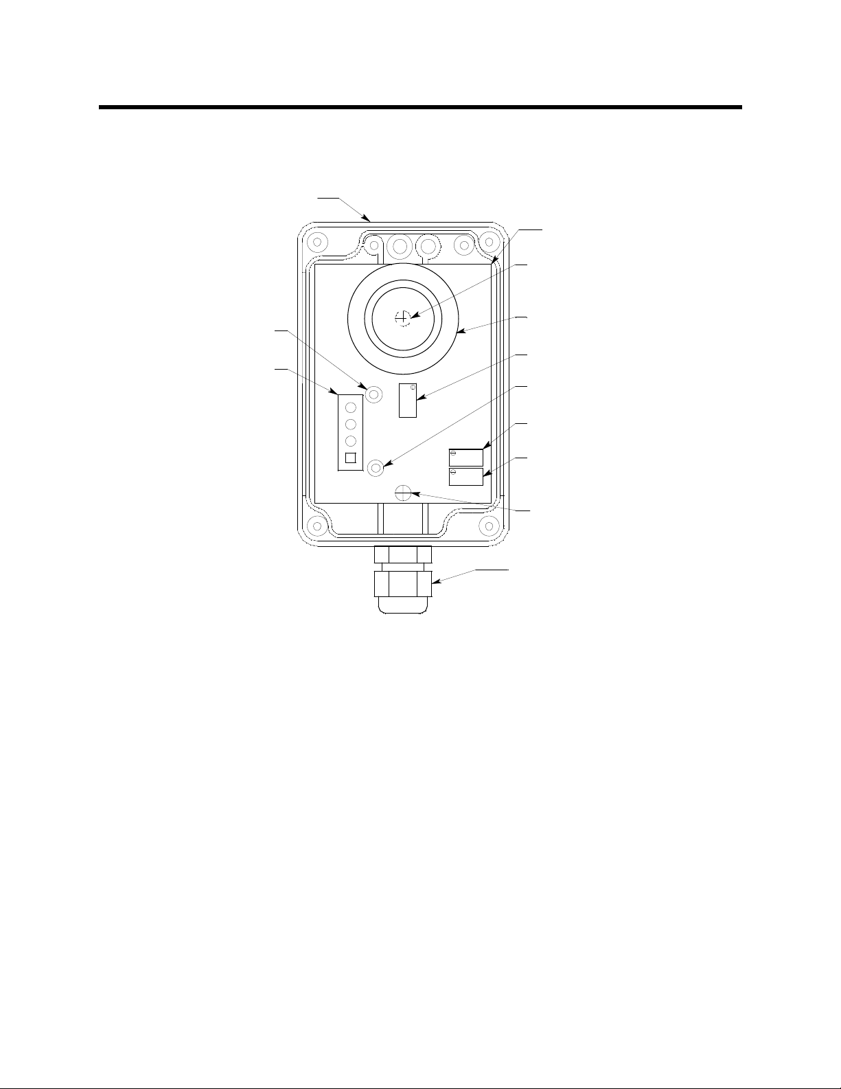
Description
Terminal Strip
This section describes the components of the H2S transmitter. The transmitter consists of
S sensor, sealing spacer, amplifier printed circuit board (PCB), and enclosure.
the H
2
Enclosure
(shown w/out cover)
Amplifier PCB
Amplifier PCB Mounting
Screw (under sensor)
Sensor (w/seal ing
Test Point
CAL+
Interconnect
CA L+
TB1
R
+V
FB
B
CAL-
ZERO
SPAN
spacer & boot)
Factory Set Pot
Test Point CAL-
Zero Pot
Span Pot
Amplifier PCB
Mounting Screw
Cable Bushing
Figure 1: H
S Transmitter Component Location
2
H2S Sensor
The sensor is cylindrical with the sensing face on the top and the connection pins on the
bottom. The sensor plugs into the amplifier PCB with the four pins. The sensor is exposed
to the ambient air through an opening in the enclosur e cover. Through a series of chemical
and electrical reactions, the sensor produces an electrical output that is proportional to the
detection range of the transmitter.
Sealing Spacer
The ring shaped plastic sea l in g spacer fills a gap in the rubber boot that is installed on the
sensor. The rubber boot is used to seal the sensor to the enclosure cover in both the CO
and H
Since a charcoal filter is not used in the H
S transmitters. In the CO transmitter the rubber boot also retains a charcoal filter.
2
S transmitter, the sealing spacer fills the space
2
that would be filled by the charcoal filter’s body.
Amplifier PCB
The amplifier PCB converts the electrical output from the sensor to a 4 to 20 mA signal
(that is proportional to the detection range) and transmits the sig na l to a gas monitoring
controller . The amplifier PCB includes the interconnect terminal strip, sensor sockets, span
pot, zero pot, and test points (see Figure 1).
2 • 65-2424RK H2S Transmitter
Page 7

Interconnect Terminal Strip
The interconnect terminal strip is the four-point terminal strip on the lower left side of the
amplifier PCB. Use the interconnect terminal strip to connect the transmitter to a
controller.
Sensor Sockets
There are four sensor sockets located in a circular pattern near the top of the amplifier
PCB. The sensor plugs into these sockets.
Span Pot
The span pot is near the bottom right corner of the amplifier PCB. Use the span pot to
adjust the transmitter’s response output during the calibration procedure.
Zero Pot
The zero pot is above the span pot. Use the zero pot to adjust the transmitter’s target gasfree output during the start-up and calibration procedures.
CAUTION: There is a third potentiometer on the PCB, the null potentiometer. It is factory-set.
Do not adjust it.
Test Points
The test points (labeled CAL+ and CAL-) are on the right of the interconnect terminal
strip. The test points produce a 100 - 500 mV output that is proportional to the
transmitter’s 4 - 20 mA output. Use the test points and a voltmeter to measure the
transmitter’s output during the start-up and calibration procedures.
Enclosure
The enclosure enables you to install the H2S transmitter at a mounting site that is remote
from the controller. The enclosure also protects the amplifier PCB and wiring connections
made to the transmitter. Use the cable bushing on the bottom of the enclosure to connect
wiring from the amplifier PCB to a controller.
Use the enclosure’s two mounting holes, accessible with the cover removed, to mount the
H
S transmitter to a vertical surface at the monitoring site. Use the cover on the front of
2
the enclosure to access the interior of the enclosure.
65-2424RK H2S Transmitter • 3
Page 8

Installation
This section describes procedures to mount the H2S transmitter in the monitoring
environment and wire the transmitter to a gas monitoring controller.
Mounting the H2S Transmitter
1. Select a mounting site that is representative of the monitoring environment. Consider
the following when you select the mounting site.
• Select a site where the transmitter is not likely to be bumped or disturbed. Make
sure there is sufficient room to perform start-up, maintenance, and calibration
procedures.
• Select a site where the target gas is likely to be found first.
NOTE: If your application does not require a specific mounting site, mo unt the
transmitter at approximately breathing level.
1.50
.54
.24
3.39
3.86
.80 max
Figure 2: Mounting the H
2.52
1.42
Ø .160 mounting hole,
2X, Accessible With Lid
Removed
Cable B ushing
S Transmitter
2
H S Sensor
2
2. Remove the enclosure’s cover by unscrewing the four cover screws, one at each
corner.
3. At the monitoring site, use #6 screws through the enclosure’s two mounting holes to
secure it to a vertical surface.
4. Secure the cover to the enclosure with the four cover screws.
4 • 65-2424RK H2S Transmitter
Page 9

Wiring the H2S Transmitter to a Controller
WARNING: Always verify that the power source is off before you make wiring
connections.
1. Tu rn off the controller.
2. Turn off or unplug incoming power at the power source end.
3. Remove the enclosure’s cover by unscrewing the four cover screws, one at each
corner.
4. Guide a two-conductor, shielded cable thr o ugh the cable bushing at the bottom of the
enclosure.
5. Connect the two wires to the interconnect terminal strip as follows (see Figure 3).
• Connect the positive wire to the terminal labeled +V.
• Connect the feedback wire to the terminal labeled FB.
CAUTION: Leave the shield drain wire insulated and disconnected at the transmitter. You will
connect the opposite end of the cabl e’s drain wire at the controller.
6. Secure the cover to the enclosure.
7. Route the cable leading from the H
S transmitter through one of the conduit hubs at
2
the controller housing.
CAUTION: Do not route controller power and transmitter wiring through the same conduit hub.
The power cabl e may disrupt the transmission o f the transmitte r signal to the
controller.
8. Connect the wires to the applicable controller transmitter terminal strip as shown in
Figure 3 below.
Controller or Recording
CAL+
TB1
R
+V
FB
B
CAL-
ZERO
SPAN
Device
+(10VDC - 30 VDC)
4 - 20 mA In (FB)
Figure 3: Wiring the H
S Transmitter to a Controller
2
65-2424RK H2S Transmitter • 5
Page 10

Start Up
9. If shielded cable is used, connect the cable’s drain wire to an available chassis (earth)
ground at the controller. RKI controllers typically have a ground stud that can be used
to ground the cable’s drain wire.
This section describes procedures to start up the H2S transmitter and place the transmitter
into normal operation.
Introducing Incoming Power
1. Complete the installation procedures described earlier in this manual.
2. Verify that the power wiring to the controller is correct and secure. Refer to the
controller operator’s manual.
3. Turn on or plug in the incoming power to the controller, then turn on the controller.
4. Verify that the controller is on and operating properly. Refer to the controller
operator’s ma nual.
CAUTION: Allow the transmitter to warm up for 5 minutes before you continue with the next
section, “Setting the Zero Signal”.
Setting the Zero Signal
NOTE: If you can verify that the detector is in a fresh air environment (environment
known to be of normal oxygen content and free of toxic and combustible gases),
it is not necessary to apply zero air when verifying or setting the fresh air
reading.
The procedure below describes applying zero emission air, usually called zero air , using a
calibration kit that includes a calibration cup, calibration gas, sample tubing, and a fixed
flow regulator with an on/off knob. RKI Instruments, Inc. recommends using a 0.5 LPM
(liters per minute) fixed flow regulator.
1. Remove the enclosure’s cover by unscrewing the four cover screws, one at each
corner.
2. Set a voltmeter to measure in the millivolt (mV) range.
3. Plug the voltmeter leads into the test points on the amplifier PCB. Plug the positive
lead into the test point labeled CAL+; plug the negative lead into the test point labeled
CAL-.
4. Screw the regulator into the zero air calibration cylinder.
5. Use the sample tubing to connect the regulator to the calibration cup.
6. Turn the regulator’s on/off knob counterclockwise to open it.
7. Hold the calibration cup against the H
sealing spacer on the sensor when calibrating. Hold the cup on gently to allow gas to
escape and avoi d pressurizing the sensor’s sensing face.
8. Allow the gas to flow for 2 minutes.
S sensor’s face. Leave the rubber boot and
2
9. Verify a voltmeter reading of 100 mV (±2 mV).
10. If necessary, use a flat-blade screwdriver to adjust the zero pot until the voltmeter
6 • 65-2424RK H2S Transmitter
Page 11

11. Turn the regulator on/off knob clockwise to close it.
12. Remove the calibration cup from the sensor face.
13. Unscrew the regulator from the zero air calibration cylinder. For convenience, leave
14. Store the components of the calibration kit in a safe and convenient place.
15. Remove the voltmeter leads from the test points.
16. Secure the cover to the enclosure.
Maintenance
This section describes maintenance procedures. It includes preventive maintenance,
troubleshooting, and component replacement procedures.
Preventive Maintenance
This section describes a preventive maintenance schedule to ensure the optimum
performance of the H
Daily
reading is 100 mV (±2 mV).
the sample tubing connected to the regulator and the calibration cup.
S transmitter. It includes daily, monthly, and quarterly procedures.
2
Verify a display reading of 0 PPM H
S at the controller. Investigate signif icant changes in
2
the display reading.
Monthly
This procedure describes a test to verify that the H
S transmitter responds properly to
2
hydrogen sulfide. It describes the test using a calibration kit that includes a calibration
cup, calibration gas, sample tubing, and a fixed flow regulator with an on/off knob. RKI
Instruments, Inc. recommends using a 0.5 LPM (liters per minute) fixed flow regulator.
NOTE: Performing a response te st on the H2S transmitter may cause alarms. Be sure to
put the controller into its calibration program or disable external alarms before
performing this test.
Preparing for the response test
1. Place the controller into its calibration program or disable external alarms.
2. Verify that the controller display reading for the channel you are testing is 0.
If the display reading is not zero, set the zero reading of the transmitter as described
in the Start Up section of this manual, then continue this procedure.
3. Screw the regulator into the calibration cylinder.
4. Use the sample tubing to connect the regulator to the calibration cup.
5. Set a voltmeter to measure in the millivolt (mV) range.
6. Remove the enclosure cover, then plug the voltmeter leads into the test points on the
amplifier PCB.
Plug the positive lead into the test point labeled CAL+; plug the negative lead into the
test point labeled CAL-.
65-2424RK H2S Transmitter • 7
Page 12

7. Use the following formula to determine the correct test points output for the test
sample.
Output (mV) = (calibrating sample/fullscale) X 400 + 100
For example, with a test sample of 25 PPM H
S and a fullscale setting of
2
100 PPM, the correct output is 200 mV.
200 (mV) = (25/100) X 400 +100
Performing the response test
1. Turn the regulator on/off knob counterclockwis e to open it. The sample will begin to
flow.
2. Hold the calibration cup against the H
S sensor’s face. Leave the rubber boot and
2
sealing spacer on the sensor when calibrating. Hold the cup on gently to allow gas to
escape and avoi d pressurizing the sensor’s sensing face.
3. When the reading on the voltmeter stabilizes, after approximately two minutes, verify
that the reading is within ± 20% of the response reading you determined earlier.
NOTE: If the readings are not within ± 20% of the correct response reading, calibrate the
transmitter as described in the Calibration section of this manual.
4. Turn the regulator on/off knob clockwise to close it.
5. Remove the calibration cup from the sensor face.
6. Unscrew the regulator from the calibration cylind er.
7. Remove the voltmeter leads from the test points.
8. Secure the cover to the enclosure.
9. When the display reading falls below the ala r m setpoints, return the controller to
normal operation.
Quarterly
Calibrate the H
S transmitter as described in the Calibration section of this manual.
2
Troubleshooting
The troubleshooting guide describes symptoms, probable causes, and recommended
action for problems you may encounter with the H
NOTE: This troubleshooting guide describes transmitter problems only. See the
controller operator’s manual for problems you may encounter with the
controller.
Fail Condition
Symptoms
• The controller indicates a fail condition.
Probable causes
• The transmitter wiring is disconnecte d or misconnected.
• The transmitter’s zero reading is low enough to cause a fail condition.
• The transmitter is malfunctioning.
S transmitter.
2
8 • 65-2424RK H2S Transmitter
Page 13

Recommended action
• Verify that the transmitter wiring is correct and secure.
• Calibrate the transmitter.
• If the fail condition continues, replace the H
S sensor.
2
• If the fail condition continues, contact RKI for further instruction.
Slow or No Response/Difficult or Unable to Calibrate
Symptoms
• The transmitter respon ds slowly or does not respond during the monthly response
test.
• Unable to accurately set the zero or response reading during the calibration
procedure.
• The tra nsmitte r requires frequent calibration.
NOTE: Under “normal” circumstances, the transmitter requires calibration once every
three months. Some applications may require a more frequent calibration
schedule.
Probable causes
• The calibration cylinder is low, out-dated, or defective.
• The transmitter is malfunctioning.
Recommended action
1. Verify that the calibrati on cylin der con t ai ns an ade qu at e suppl y of a fresh test sample.
2. If the calibration/response difficulties continue, replace the H
S sensor as described
2
later in this section.
3. If the calibration/response difficulties continue, contact RKI Instruments, Inc. for
further instruction.
Replacing Components of the H2S Transmitter
This section includes procedures to replace the H2S sensor, amplifier PCB, and charcoal
filter.
Replacing the Sensor
1. Tu rn off the controller.
2. Turn off or unplug incoming power at the power source end.
3. Remove the enclosure’s cover by unscrewing the four cover screws, one at each
corner.
4. Unplug t he H
5. Remove the rub ber boot and sealing spacer from the ol d sensor and install onto the
replacement sensor.
6. Carefully plug the replacement sensor into the socket pattern on the amplifier PCB.
NOTE: Match the sensor’s male pins with the four female sockets as you plug the sensor
into the sockets.
S sensor from the amplifie r PCB.
2
65-2424RK H2S Transmitter • 9
Page 14

7. Secure the cover to the enclosure.
8. Turn on or plug in incoming power at the power source end.
9. Turn on the controller.
CAUTION: Allow the r ep la cem ent sens or to w arm up for 5 m inu tes before you continue with the
next step.
10. Calibrate the replacement sensor as described in the Calibration section of this
manual.
Replacing the Amplifier PCB
1. Tu rn off the controller.
2. Turn off or unplug incoming power at the power source end.
3. Remove the enclosure’s cover by unscrewing the four cover screws, one at each
corner.
4. Disconnect the wires from the interconnect terminal strip.
5. Unplug t he H
S sensor from the amplifier PCB to access one of the PCB mounting
2
screws.
6. Unscrew and remove the two screws that secure the amplifier PCB to the enclosure.
The screws are near the top and bottom of the amplifier PCB.
7. Remove the amplifier PCB.
8. Place the new amplifier PCB in the same position as the one you removed in step 6.
9. Use the two screws you removed in step 5 to secure the PCB to the enclosure.
10. Reconnect the wiring from the controller to the interconnect terminal strip as shown
in Table 2 and Figure 3.
Table 2: Reconnecting the H
Amplifier PCB
Interconnect Terminal Strip
11. Carefully plug the H
FB
+V
S sensor with rubber boot and charcoal filter into the socket
2
S Transmitter to a Controller
2
Controller
Transmitter Terminal Strip
(typical)
4 - 20 (FB)
+ V (10 VDC - 30 VDC)
pattern on the amplifier PCB.
NOTE: Match the sensor’s male pins with the four female sockets as you plug the sensor
into the sockets.
12. Secure the cover to the enclosure.
13. Turn on or plug in incoming power at the power source end.
14. Turn on the controller.
CAUTION: Allow the sensor to warm up for 5 minutes before you continue with the next step.
10 • 65-2424RK H2S Transmitter
Page 15

15. Calibrate the H2S transmitter as described in the Calibration sectio n of this insert.
Calibration Frequency
Although there is no particular calibration frequency that is correct for all applications, a
calibration frequency of every 3 to 6 months is adequate for most H
applications. Unless experience in a particular application dictates otherwise, RKI
Instruments, Inc. recommends a calibration frequency of every 3 months.
If an application is not very demanding, for example detection in a clean, temperature
controlled environment where H
are minimal at calibration, then a calibration frequency of every 6 months is adequate.
S transmitter
2
S is not normally present and calibration adjustments
2
Calibration
If an application is very demanding, for example if H
concentrations or the environment is not well controlled, then more frequent calibration
than every 3 months may be necessary.
This section describes how to calibrate the H2S transmitter. It includes procedures to
prepare for calibration, set the zero reading, set the response reading, and return to
normal operation. It describes th e te st using a calibration kit that includes a calibration
cup, calibration gas, sample tubing, and a fixed flow regulator with an on/off knob. RKI
Instruments, Inc. recommends using a 0.5 LPM (liters per minute) fixed flow regulator.
S is present often and in signifi c ant
2
Prepari ng for Ca libration
NOTE: Calibrating the H2S transmitter may cause alarms. Be sure to put the controller
into its calibration program or disable external alarms before calibrating.
1. Screw the regulator into the zero air calibration cylinder.
2. Use the calibration kit sample tubing to connect the regulator to the calibration cup.
3. Set a voltmeter to measure in the millivolt (mV) range.
4. Remove the enclosure cover, then plug the voltmeter leads into the test points on the
amplifier PCB.
Plug the positive lead into the test point labeled CAL+; plug the negative lead into the
test point labeled CAL-.
5. Use the following formula to determine the correct test points output for the
calibrating sample.
Output (mV) = (calibrating sample/fullscale) X 400 + 100
For example, with a calibrating sample of 25 PPM H
100 PPM, the correct output is 200 mV.
200 (mV) = (25/100) X 400 +100
S and a fullscale set t ing of
2
65-2424RK H2S Transmitter • 11
Page 16

Setting the Zero Reading
NOTE If you can verify that the H2S transmitter is in a fresh air environment, you do not
need to apply zero air to the detector before adjusting the zero reading.
1. Turn the regulator on/off knob counterclockwise to open it.
2. Hold the calibration cup against the H
S sensor’s face. Leave the rubber boot and
2
sealing spacer on the sensor when calibrating. Hold the cup on gently to allow gas to
escape and avoi d pressurizing the sensor’s sensing face.
3. Allow the gas to flow for 2 minutes.
4. Verify a reading of 100 mV (± 2mV).
5. If necessary, use the zero pot on the amplifier PCB to adjust the reading to 100 mV
(± 2mV).
6. Turn the regulator on/off knob clockwise to close it.
7. Remove the calibration cup from the sensor face.
8. Unscrew the regulator from the zero air calibration cylinder.
Leave the sample tubing connected to the regulator and the calibration cup.
Setting the Response Reading
1. Screw the regulator into the calibration cylinder. Verify that the calibration gas is
representative of the transmitter’s target gas.
2. Turn the regulator on/off knob counterclockwise to open it.
3. Hold the calibration cup against the H
sealing spacer on the sensor when calibrating. Hold the cup on gently to allow gas to
escape and avoi d pressurizing the sensor’s sensing face.
4. Allow the gas to flow for 2 minutes.
5. Verify that the reading matches the response reading (± 2mV) you determined earlier.
S sensor’s face. Leave the rubber boot and
2
6. If necessary, use the span pot on the amplifier PCB to adjust the reading to match the
correct response reading.
7. Turn the regulator on/off knob clockwise to close it.
8. Remove the calibration cup from the sensor face.
9. Unscrew the regulator from the calibration cylind er.
NOTE: For convenience, leave the components of the calibration kit connected by the
sample tubing.
Returning to Normal Operation
1. Remove the voltmeter leads from the amplifier test points.
2. Secure the cover to the enclosure.
3. When the display reading falls below the ala r m setpoints, return the controller to
normal operation.
4. Verify that the controller display reading decreases and stabilizes at 0 ppm H
12 • 65-2424RK H2S Transmitter
S.
2
Page 17

Parts List
5. Store the components of the calibration kit in a safe and convenient place.
Table 6 lists replacement parts and accessories for the H2S channel.
Table 3: Parts List
Part Number Description
06-1248RK Sample tubing (order by the foot)
07-0203RK Retaining boot (for filter)
14-2101RK Sealing spacer
57-0035RK-02 Amplifier PCB, H
65-2424RK H
S transmitter, complete
2
71-0062RK 65-2424RK H
81-0151RK-04 Calibration cylinder (25 PPM H
S
2
S Transmitter Manual (this document)
2
S in nitrogen, 34 liter)
2
81-0076RK-01 Zero air calibration cylinder (34 liter)
81-1050RK Regulator with gauge and knob, 0.5 LPM, for 17 liter an d 34 liter
steel calibration cylinders
81-1 10 9R K Calibration cup
ES-1537-H2S H
S replacement sensor
2
65-2424RK H2S Transmitter • 13
 Loading...