

Page 1

65-2400RK
Combustible Gas Transmitter
Operator’s Manual
Part Number: 71-0060RK
Revision: C
Released: 1/31/13
www.rkiinstruments.com
Page 2

WARNING
Read and understand this instruction manual before operating
detector . Improper use of the dete ctor could result in bodily harm
or death.
Periodic calibration and maintenance of the detector is essential
for proper operation and correct readings. Please calibrate and
maintain this detector regularly! Frequency of calibration
depends upon the type of use you have and the sensor types.
T ypical calibration frequencies for most applications a re between
3 and 6 months, but can be required more often or less often
based on your usage.
65-2400RK Combustible Gas Transmitter
Page 3

Product Warranty
RKI Instruments, Inc. warrants gas alarm equipment sold by us to be free from defects in
materials, workmanship, and performance for a period of one year fr o m date of shipment
from RKI Instruments, Inc. Any parts found defective withi n tha t period will be repaired
or replaced, at our option, free of charge. This warranty does not apply to those items
which by their nature are subject to deterioration or consumption in normal ser v ice, and
which must be cleaned, repaired, or replaced on a routine basis. Examples of such items
are:
W arranty is voided by abuse including mechanical damage, alteration, rough handling, or
repair procedures not in accordance with the operator’s manual. This warranty indicates
the full extent of our liability , a nd we are not r esponsible for removal or r eplacement costs,
local repair costs, transportation costs, or contingent expenses incurred without our prior
approval.
a) Absorbent cartridges d) Batteries
b) Pump diaphragms and valves e) Filter elements
c) Fuses
THIS WARRANTY IS EXPRESSLY IN LIEU OF ANY AND ALL OTHER
WARRANTIES AND REPRESENTATIONS, EXPRESSED OR IMPLIED,
AND ALL OTHER OBLIGATIONS OR LIABILITIES ON THE PART OF
RKI INSTRUMENTS, INC. INCLUDING BUT NOT LIMITED TO, THE
WARRANTY OF MERCHANTABILITY OR FITNESS FOR A
PARTICULAR PURPOSE. IN NO EVENT SHALL RKI INSTRUMENTS,
INC. BE LIABLE FOR INDIRECT, INCIDENTAL, OR CONSEQUENTIAL
LOSS OR DAMAGE OF ANY KIND CONNECTED WITH THE USE OF
ITS PRODUCTS OR FAILURE OF ITS PRODUCTS TO FUNCTION OR
OPERATE PROPERLY.
This warranty covers instruments and parts sold to users by authorized distributors,
dealers, and representatives as appointed by RKI Instruments, Inc.
We do not assum e i ndemnification for any accident or damage caused by the op e r a t ion of
this gas monitor, and our warranty is limited to the replacement of parts or our complete
goods.
65-2400RK Combustible Ga s Tr ans mitte r
Page 4

Table of Contents
Overview . . . . . . . . . . . . . . . . . . . . . . . . . . . . . . . . . . . . . . . . . . . . . . . . . . . . . . . . . . . . . . . . . . . 1
Specifications. . . . . . . . . . . . . . . . . . . . . . . . . . . . . . . . . . . . . . . . . . . . . . . . . . . . . . . . . . . . . . . . 1
Description. . . . . . . . . . . . . . . . . . . . . . . . . . . . . . . . . . . . . . . . . . . . . . . . . . . . . . . . . . . . . . . . . . 2
Combustible Gas Detector. . . . . . . . . . . . . . . . . . . . . . . . . . . . . . . . . . . . . . . . . . . . . . . . . . . . . . . . . . . . . . 2
Amplifier . . . . . . . . . . . . . . . . . . . . . . . . . . . . . . . . . . . . . . . . . . . . . . . . . . . . . . . . . . . . . . . . . . . . . . . . . . . . 3
Junction Box. . . . . . . . . . . . . . . . . . . . . . . . . . . . . . . . . . . . . . . . . . . . . . . . . . . . . . . . . . . . . . . . . . . . . . . . . . 4
Installation . . . . . . . . . . . . . . . . . . . . . . . . . . . . . . . . . . . . . . . . . . . . . . . . . . . . . . . . . . . . . . . . . . 5
Mounting the Combustible Gas Transmitter . . . . . . . . . . . . . . . . . . . . . . . . . . . . . . . . . . . . . . . . . . . . . . 5
Wiring the Combustible Gas Transmitter . . . . . . . . . . . . . . . . . . . . . . . . . . . . . . . . . . . . . . . . . . . . . . . . . 6
Startup. . . . . . . . . . . . . . . . . . . . . . . . . . . . . . . . . . . . . . . . . . . . . . . . . . . . . . . . . . . . . . . . . . . . . . 8
Introducing Incoming Power . . . . . . . . . . . . . . . . . . . . . . . . . . . . . . . . . . . . . . . . . . . . . . . . . . . . . . . . . . . 8
Setting the Zero Signal. . . . . . . . . . . . . . . . . . . . . . . . . . . . . . . . . . . . . . . . . . . . . . . . . . . . . . . . . . . . . . . . . 8
Maintenance. . . . . . . . . . . . . . . . . . . . . . . . . . . . . . . . . . . . . . . . . . . . . . . . . . . . . . . . . . . . . . . . . 9
Preventive Maintenance . . . . . . . . . . . . . . . . . . . . . . . . . . . . . . . . . . . . . . . . . . . . . . . . . . . . . . . . . . . . . . . 9
Troubleshooting . . . . . . . . . . . . . . . . . . . . . . . . . . . . . . . . . . . . . . . . . . . . . . . . . . . . . . . . . . . . . . . . . . . . . 11
Replacing Components of the Combustible Gas Transmitter . . . . . . . . . . . . . . . . . . . . . . . . . . . . . . . 12
Calibration Frequency . . . . . . . . . . . . . . . . . . . . . . . . . . . . . . . . . . . . . . . . . . . . . . . . . . . . . . . 13
Calibration . . . . . . . . . . . . . . . . . . . . . . . . . . . . . . . . . . . . . . . . . . . . . . . . . . . . . . . . . . . . . . . . . 14
Preparing for Calibration. . . . . . . . . . . . . . . . . . . . . . . . . . . . . . . . . . . . . . . . . . . . . . . . . . . . . . . . . . . . . . 14
Setting the Zero Reading. . . . . . . . . . . . . . . . . . . . . . . . . . . . . . . . . . . . . . . . . . . . . . . . . . . . . . . . . . . . . . 14
Setting the Response Reading. . . . . . . . . . . . . . . . . . . . . . . . . . . . . . . . . . . . . . . . . . . . . . . . . . . . . . . . . . 15
Returning to Normal Operation. . . . . . . . . . . . . . . . . . . . . . . . . . . . . . . . . . . . . . . . . . . . . . . . . . . . . . . . 15
Parts List . . . . . . . . . . . . . . . . . . . . . . . . . . . . . . . . . . . . . . . . . . . . . . . . . . . . . . . . . . . . . . . . . . . 16
65-2400RK Combustible Gas Transmitter
Page 5

Overview
This manual describes the 65-2400RK combustible gas transmitter. This manual also
describes how to install, start up, con fi gure, mainta in, a nd ca librate the transmitter when
it is used with a gas monitoring controller. A parts list at the end of this manual lists
replacement parts and accessories for the combustible gas transmitter.
Specifications
Table 1 lists specifications for th e combustible gas transmitter.
Target Gas Combustible gas
Area Classification Explosionproof for Class I, Groups B, C, and D
Sampling Method Diffusion
Signal Output 4 to 20 mA
Table 1:Specifications
Description Specification
Detection Range 0 to 100% LEL
Accuracy ± 5% of reading or ± 2% LEL (whichever is greater)
Response Time 90% in 45 seconds
W ARNING: When using the 65-2400RK, you must follow the instructions and warnings
in this manual to assure proper and safe operation of the 65-2400RK and to
minimize the risk of personal injury. Be sure to maintain and period ically
calibrate the 65-2400RK as described in this manual.
65-2400RK Combustible Gas Transm itter • 1
Page 6
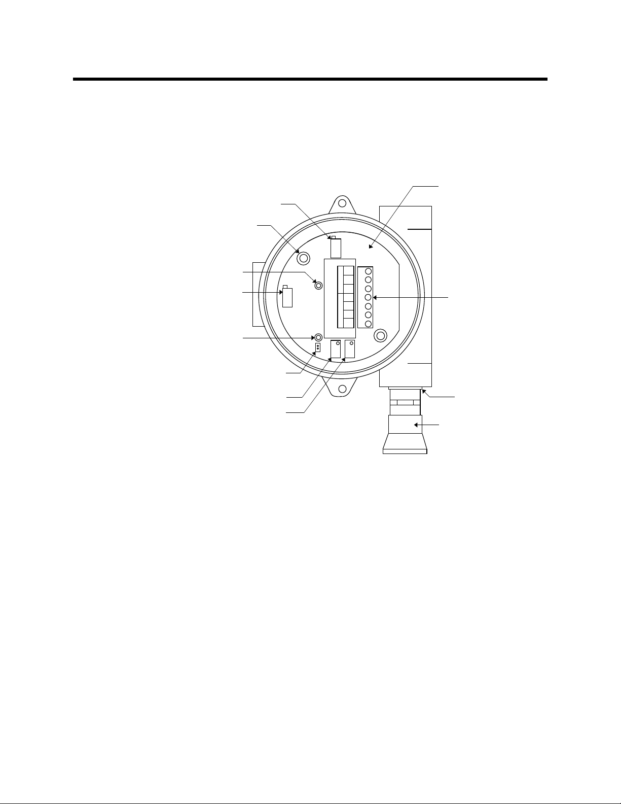
Description
GND
24V
4-20
RED
WHT
GRN
BLK
SENSOR POWER/SIG
TP+
TP-
Combustible gas
amplifier
Interconnect
terminal strip
Test point (-)
Securing screw (2)
Test point (+)
Reducer
(3/4 in. x 1/2 in.)
Combustible gas
detector
Zero potentiometer
Span potentiometer
Potentiometer
(
factory set)
Potentiometer
(factory set)
Jumper pins
(factory use only)
This section describes the components of the combustible gas transmitter. The transmitter
is a 4 - 20 mA type detector head. It consists of the combustible gas detector, amplifier , and
junction box.
Figure 1: Combustible Gas Transmitter Component Location
Combustible Gas Detector
The combustible gas detector includes the sensing elements, flame arrestor, detector
housing, and detector leads.
Sensing Elements
Two sensing elements are protected within the detector assembly. Through a series of
thermal and electronic reactions, these elements produce an electrical outpu t that is
proportional to the detection range of the transmitter.
Flame Arrestor
The porous flame arrestor allows the target gas to diffuse into the detector assembly and
contact the sensing elements. The flame arrestor also contains sparks within the detector.
2 • 65-2400RK Combustible Gas Transmitter
Page 7

Detector Housing
The sensing elements and flame arrestor are installed within the detector housing.
Mounting threads (1/2 in. NPT) at the top of the detector allow you to mount the
combustible gas detector into the bottom conduit hub of the junction box. A rainshield
screws onto the bottom of the detector. The rainsh ield helps protect the detector from
debris in the monitoring environment.
Detector Leads
Four color-coded leads extend from the top of the detector. The leads allow you to connect
the combustible gas detector to the amplifier.
Amplifier
The amplifier converts the electrical output from the detector to a 4 to 20 mA sig nal th at is
proportional to the detection range and transmits the signal to a gas monitoring controller .
The amplifier includes the interconnect terminal strip, span pot, zero pot, and test points
(see Figure 1).
Interconnect Terminal Strip
The interconnect terminal strip is a seven-point terminal strip. Use the interconnect
terminal strip to connect the combustible gas detector to the amplifier and the amplifier to
a controller.
NOTE: The combustible gas detector is factory-wired to the amplifier. See the
Installation section of this man ual for all wiring procedures related to the
transmitter.
Span Pot
The span pot is near the bottom of the amplifier (see Figure 1). Use the span pot to adjust
the transmitter’s response output during the calibration procedure.
Zero Pot
The zero pot is to the right of the span pot (see Figure 1). Use the zero pot to adjust the
transmitter’s target gas-free output during the start-up and calibration procedures.
CAUTION: The amplifier includes two additional potentiometers. They are factory-set. Do not
adjust them.
Test Points
The test points (labeled TP+ and TP-) are to the left of the interconnect terminal strip
(see Figure 1). The test points produce a 100 to 500 mV output that is proportiona l to the
transmitter’s 4 to 20 mA output. Use the test points and a voltme ter to mea sure the
transmitter’s output during the start-up and calibration procedures.
65-2400RK Combustible Gas Transm itter • 3
Page 8

Junction Box
Use the junction box to install the comb ustible gas transmitter at a mounting site that is
remote from the contro ller. The juncti on box also protects the amp lifier a nd wiring
connections made to the amplifier. Use the two 3/4 in. conduit hubs to mount the detector
to the junction box (bottom hub) and connect wiring from the amplifier to the controller
(top hub). The detector has 1/2 in. NPT mounting threads, so a 3/4 in NP T. x 1/2 in. NPT
reducer is used to mount it.
NOTE: The combustible gas detector and amplifier are factory-mounted to the
junction box.
Use the junction box’s two mountin g holes to mount the combustible gas transmitter to a
vertical surface at the monitoring site. Use the cover on the front of the junction box to
access the interior of the junction box.
4 • 65-2400RK Combustible Gas Transmitter
Page 9

Installation
2.3 in.
(5.8 cm)
5.2 in.
Note: The junction box is
4.6 in. (11.7 cm) deep.
(13.2 cm)
7.7 in. (max.)
(19.6 cm)
5.46 in.
(13.9 cm)
2.75 in.
(7.0 cm)
0.25 in.
DIA.
This section describes procedures to mount the combustibl e gas transmitter in the
monitoring environment and wire the transmitter to the controller.
Mounting the Combustible Gas Transmitter
1. Select a mounting site that is representative of the monitoring environment. Consider
the following when you select the mounting site.
• Select a site where the transmitter is not likely to be bumped or disturbed. Make
sure there is sufficient room to perform start-up, maintenance, and calibration
procedures.
• Select a site where the target gas is likely to be found first. For lighter gases,
mount the detector near the ceiling; for heavier gases, mount the detector near the
floor.
Figure 2: Mounting the Combustible Gas Transmitter
If the combustible gas detector is mounted to the junction box, skip to step 5. If not,
continue with step 2.
2. Remove the junction box cover.
3. Guide the four wires that extend from the top of the combustible gas detector through
the bottom conduit hub of the junction box.
4. Screw the combustible gas detector into the bottom cond uit hub of the junction box.
5. At the monitoring site, use #10 screws through the junction box’s two mounting holes
to secure the junction box to a vertical surface.
CAUTION: Mount the combustible gas trans mitte r wi th th e d etector f aci ng down (see F igure 2).
65-2400RK Combustible Gas Transm itter • 5
Page 10

Wiring the Combustible Gas Transmitter to a Controller
WARNING : Always verify that the power source is off before you make wiring
connections.
1. Turn off power to the controller.
2. Place the controller’s power switch in the OFF position.
3. Remove the junction box cover.
4. Verify that the detector leads are wired to the amplifier’s interconnect terminal strip.
If necessary, connect the detector leads to the interconnect terminal strip as shown in
Figure 3.
5. Guide a three-conductor, shield ed cable or three wires in conduit through the top
conduit hub of the junction box.
6. Connect the three wires to the interconnect terminal strip as follows (see Figure 3).
• Connect the positive wire to the 24VDC terminal.
• Connect the feedback wire to the 4-20 (FB) terminal.
• Connect the negative wire to the DC - terminal.
CAUTION: If shielded cable is used, leave the cable s hie ld’s drain wire insulated and
disconnected at the transmitter. You will connect the opposite end of the cable’s drain
wire at the controller to chassis ground.
7. Secure the junction box cover to the junction box.
8. Route the cable or wires leading from the combustible gas transmitter through one of
the conduit hubs at the controller housing.
CAUTION: Do not route power and transmitter wiring through the same conduit hub. The
power cable may disrupt the transmission of the transmitter signa l to the
controller.
9. Connect the wires to the applicable transmitter terminal strip at the controller as
shown in Figure 3 below.
6 • 65-2400RK Combustible Gas Transmitter
Page 11

GND
24V
4-20
RED
WHT
GRN
BLK
SENSOR POWER/SIG
TP+
TP-
Black
Green
White
Red
Controller Transmitter
Terminals,Typical
- (DC -)
+ 24 VDC
4 - 20 mA In (FB or S)
Cable Shield
Figure 3: Wiring the Combustible Gas Transmitter to a Controller
10. If shielded cable is used, connect the cable’s drain wire to an available chassis grou nd
at the controller. RKI controllers typically have a ground stud that can be used to
ground the cable’s drain wire.
65-2400RK Combustible Gas Transm itter • 7
Page 12

Start Up
This section describes procedures to start up the combustible gas transmitter and place th e
transmitter into normal operation.
Introducing Incoming Power
1. Complete the installation procedures described earlier in this manual.
2. Verify that the power wiring to the controller is correct and secure. Refer to the
controller operator’s manual.
3. Turn on or plug in power to the controller, then place the contr oller’s power switch in
the ON position.
4. Verify that the controller is on and operating properly. Refer to the controller
operator’s ma nual.
CAUTION: Allow the detector to warm up for 5 minutes before you continue with the next
section, “Setting the Zero Signal”.
Setting the Zero Signal
NOTE: If you can verify that the detector is in a fresh air environment (environment
known to be of normal oxygen content and free of toxic and combustible gases),
it is not necessary to apply zero air when verifying or setting the fresh air
reading.
The procedure below describes applying zero emission air, usually called zero air , using a
calibration kit that includes a calibration cup, calibration gas, sample tubing, and a fixed
flow regulator with an on/off knob. RKI Instruments, Inc. recommends using a 0.5 LPM
(liters per minute) fixed flow regulator.
1. Unscrew and remove the junction box cover from the junction box.
2. Set a voltmeter to measure in the millivolt (mV) range.
3. Plug the voltmeter leads into the test points on the amplifier. Plug the positive lead
into the test point labeled TP+; plug the ne gative lead into the test point labeled TP-.
4. Screw the calibration cup onto the bottom of the detector.
5. Screw the regulator into the zero air calibration cylinder.
6. Use the sample tubing to connect the regulator to the calibration cup.
7. Turn the regulator’s on/off knob counterclockwise to open it.
8. Verify a voltmeter re ading of 100 mV (±2 mV).
9. If necessary, use a flat-blade screwdriver to adjust the zero pot until the voltmeter
reading is 100 mV (±2 mV).
10. Turn the regulator’s on/off knob clockwise to close it.
11. Unscrew the calibration cup from the detector. For convenience, leave the sample
tubing connected to the regulator and the calibration cup.
12. Store the components of the calibration kit in a safe and convenient place.
13. Remove the voltmeter leads from the test points.
14. Secure the junction box cover to the junction box.
8 • 65-2400RK Combustible Gas Transmitter
Page 13

Maintenance
This section describes maintenance procedures. It includes preventive maintenance,
troubleshooting, and component replacement procedures.
Preventive Maintenance
This section describes a preventive maintenance schedule to ensure the optimum
performance of the combustible gas transmitter. It includes daily, monthly, and quarterly
procedures.
Daily
Verify a display reading of 0%LEL at the controller. Investigate significant changes in the
display reading.
Monthly
This procedure describes a test to verify that the combustible gas transmitter responds
properly to the target gas. It describes the test using a calibration kit that includes a
calibration cup, calibration gas, sample tubing, and a fixed flow regulator with an on/o ff
knob. RKI Instruments, Inc. recommends using a 0.5 LPM ( liters per minute) fixed flow
regulator.
NOTE: Performing a response test on the combustible transmitter may cause alarms. Be
sure to put the controller into its calibration program or disable external alarms
before performing this test.
Preparing for the response test
1. Place the controller into its calibration program or disable external alarms.
2. Verify that the controller display reading for the cha nnel you are testing is 0 %LEL.
If the display reading is not zero, set the zero reading of the transmitter as described
in “Start Up” on page 8 of this manual, then continue this procedure.
3. Screw the calibration cup onto the bottom of the combustible detector.
4. Screw the regulator into the calibration cylinder.
5. Use the calibration kit sample tubing to connect the regulator to the calibration cup.
6. Set a voltmeter to measure in the millivolt (mV) range.
7. Remove the junction box cover, then plug the voltmeter leads into the test points on
the amplifier.
Plug the positive lead into the test point labeled TP+; plug the negative lead into the
test point labeled TP-.
8. Use the following formula to determine the correct test points output for the test
sample.
Output (mV) = (calibrating sample/fullscale) X 400 + 100
For example, with a test sample of 50% LEL and a fullscale setting of 100% LEL, the
correct output is 300 mV.
300 (mV) = (50/100) X 400 +100
Performing the response test
1. Turn the regulator’s on/off knob counterclockwise to open it. The sample gas will
65-2400RK Combustible Gas Transm itter • 9
Page 14

begin to flow.
2. Allow the gas to flow for two minutes, then verify that the reading is within ± 20% of
the response reading you determined earlier.
NOTE: If the reading is not within ± 20% of the correct response reading, calibrate the
transmitter as described in “Calibration” on page 14 of this manual.
3. Turn the regulator’s on/off knob clockwise to close it.
4. Unscrew the regulator from the calibration cylind er.
5. Unscrew the calibration cup from the detector.
6. Remove the voltmeter leads from the amplifier test poin ts.
7. Reinstall the junction box cover.
8. When the controller display reading falls below th e alarm setpoints, return the
controller to normal operation.
Quarterly
Calibrate the combustible gas transmitter as described in “Calibration” on page 14 of this
manual.
10 • 65-2400RK Combustible Gas Transmitter
Page 15

Troubleshooting
The troubleshooting guide describes symptoms, probable causes, and recommended
action for problems you may encounter with the combustible gas transmitter.
NOTE: This troubleshooting guide describes transmitter problems only. See the
controller operator’s manual for problems you may encounter with the
controller.
Table 2:Troubleshooting the Combustible Gas Transmitter
Condition Symptom(s) Probable Causes Recommended Action
Fail Condition • Controller indicates a
Slow or No
Response/
Difficult or
Unable to
Calibrate
fail condition.
• Transmitter responds
slowly or does not
respond to response
test.
• Unable to accurately
set the zero or
response reading
during calibration.
• Transmitter requires
frequent calibration.
Note: Under “normal”
circumstances, the
transmitter requires
calibration once every
three mont hs.
Some applications
may require a more
frequent calibration
schedule.
• The transmitter wiring
is disconnected or
misconnected.
• The transmitters zero
reading is low enough
to cause a fail
condition.
• The transmitter is
malfunctioning.
• The calibration cylinder
is low, out-dated, or
defective.
• The transmitter is
malfunctioning.
1. Verify that the transmitter wiring is
correct and secure.
2. Calibrate the transm itt er.
3. If the fail condition continues, replace
the detector.
4. If the fail condition continues, contact
RKI for further instruction.
1. Verify that the calibration cylinder
contains an adequate supply of a
fresh test sample.
2. Verify that the regulator used for
calibration is a 0.5 LPM regulator.
3. If the calibration/response difficulties
continue, replace the detector.
4. If the calibration/response difficulties
continue, contact RKI for further
instruction.
65-2400RK Combustible Gas Transm itter • 11
Page 16

Replacing Components of the Combustible Gas Transmitter
This section includes procedures to replace the combustible gas detector and amplifier.
Replacing the Combustible Gas Detector
1. Turn off power to the controller.
2. Place the controller’s power switch in the OFF position.
3. Remove the junction box cover.
4. Disconnect the detector leads from the interconnect terminal strip. Note the posit ion
of the color-coded leads as you remove them.
5. Unscrew the detector from the junction box.
6. Guide the detector leads of the replacement detector through the bottom conduit hub
of the junction box, then screw the mounting threads of the detector into the conduit
hub.
7. Connect the detector leads to the interconnect terminal strip as shown in Table 3
below and Figure 3 on page 7 of th is manual.
Table 3: Reconnecting the Combustible Gas
Detector to the Amplifier
Detector Lead
Red RED
White WHT
Green GRN
Black BLK
Amplifier Interconnect
Terminal Strip
8. Turn on power to the controller.
9. Place the controller’s power switch in the ON position.
CAUTION: Allow the replacement detector to warm up for 5 minutes before you co ntinue with
the next step.
10. Calibrate the replacement detector as described in “Calibration” on page 14 of this
manual.
Replacing the Amplifier
1. Turn off power to the controller
2. Place the controller’s power switch in the OFF position.
3. Remove the junction box cover.
4. Disconnect the detector leads from the interconnect terminal strip.
5. Disconnect the wiring that connects the combustible gas transmitter to the controller
from the amplifier’s interconnect terminal strip.
6. Unscrew and remove the two screws that secure the amplifier to the junction box.
The screws are at the top left and bottom right of the amplifier.
7. Remove the amplifier.
12 • 65-2400RK Combustible Gas Transmitter
Page 17

8. Place the new amplifier in the same position as the amplifier you removed in the
previous step.
9. Use the two screws you removed in step 5 to secure the amplifier to the junction box.
10. Reconnect the wiring that connects the controller to the combustible gas transmitter at
the amplifier’s interconnect terminal strip as shown in Table 4 below and Figure 3 on
page 7 of this manual.
Table 4: Reconnecting the Combustible Gas Amplifier
to the Controller
Amplifier Interconnect
T erminal Strip
GND
4-20 4 - 20 mA (FB or S)
24V + 24V
Controller
Transmitter Terminal
Strip (typical)
- (DC -)
11. Reconnect the detector leads to the amplifier’s interconnect terminal strip as shown in
Table 5 below and Figure 3 on page 7 of this manual.
Table 5: Reconnecting the Combustible Gas
Detector to the Amplifier
Detector Lead
Red RED
White WHT
Green GRN
Black BLK
Amplifier Interconnect
Terminal Strip
12. Turn on power to the controller.
13. Turn on the controller and place it into normal operation.
CAUTION: Allow the detector to warm up for 5 minutes before you continue with the next ste p.
14. Calibrate the combustible gas transmitter as described in “Calibration” on page 14 of
this manual.
Calibration Frequency
Although there is no particular calibration frequency that is correct for all applications, a
calibration frequency of every 3 to 6 months is adequate for most combustible gas
transmitter applications. Unless experience in a particular application dictates otherwise,
RKI Instruments, Inc. recommends a calibration frequency of every 3 months.
If an application is not very demanding, for example detection in a clean, temperature
controlled environment where combustible gas is not normally present and calibration
65-2400RK Combustible Gas Transm itter • 13
Page 18

Calibration
adjustments are minimal at calibration, then a calibration frequency of every 6 months is
adequate.
If an application is very demanding, for example if combustible gas is present often and in
significant concentrations or the environment is not well controlled, then more frequent
calibration than e v ery 3 mo nt h s m ay be n e ces s ary. If potential catalyst poisons are known
or likely to be present, more frequent calibration than every 3 months will be necessary.
This section describes how to calibrate the combustible gas transmitter. It includes
procedures to prepare for calibration, set the zero reading, set the response reading, and
return to normal operation. It describes the test using a calibration kit that includes a
calibration cup, calibration gas, sample tubing, and a fixed flow regulator with an on/o ff
knob. RKI Instruments, Inc. recommends using a 0.5 LPM ( liters per minute) fixed flow
regulator.
Prepari ng for Ca libration
NOTE: Calibrating the combustible transmitter may cause alarms . Be sure to put the
controller into its calibration program or disable external alarms before
continuing.
1. Screw the calibration cup onto the bottom of the combustible gas detector.
2. Screw the regulator into the zero air calibration cylinder.
3. Use the sample tubing to connect the regulator to the calibration cup.
4. Set a voltmeter to measure in the millivolt (mV) range.
5. Remove the junction box cover, then plug the voltmeter leads into the test points on
the amplifier.
Plug the positive lead into the test point labeled TP+; plug the negative lead into the
test point labeled TP-.
6. Use the following formula to determine the correct test points output for the
calibrating sample.
Output (mV) = (calibrating sample/fullscale) X 400 + 100
For example, with a calibrating sample of 50% LEL and a fullscale setting of
100% LEL, the correct output is 300 mV.
300 (mV) = (50/100) X 400 +100
Setting the Zero Reading
NOTE: If you can verify that the combustible transmitter is in a fresh air environment,
you do not need to apply zero air to the detector before adjusting the zero
reading.
1. Turn the regulator’s on/off knob counterclockwise to open it. The sample will begi n
to flow.
2. Allow the gas to flow for two minutes.
3. Verify a reading of 100 mV (±2 mV).
14 • 65-2400RK Combustible Gas Transmitter
Page 19

4. If necessary, use the zero pot on the amplifier to adjust the reading to 100 mV (±2 mV).
5. Turn the regulator’s on/off knob clockwise to close it.
6. Unscrew the regulator from the zero air calibration cylinder.
Leave the sample tubing connected to the regulator and the calibration cup.
Setting the Response Reading
1. Screw the regulator into the calibration cylinder. Verify that the calibrating gas is
representative of the transmitter’s target gas.
2. Turn the regulator’s on/off knob counterclockwise to open it.
3. Allow the sample gas to flow for two mi nutes.
4. Verify that the reading matches the response reading (±2 mV) you determined earlier.
5. If necessary, use the span pot on the amplifier to adjust the reading to match the
correct response reading.
6. Turn the regulator’s on/off knob clockwise to close it.
7. Unscrew the regulator from the calibration cylind er.
8. Unscrew the calibration cup from the detector.
NOTE: For convenience, leave the regulator and calibration cup connected by the
sample tubing.
Returning to Normal Operation
1. Remove the voltmeter leads from the amplifier test poin ts.
2. Secure the junction box cover to the junction box.
3. When the display reading falls below the ala r m setpoints, return the controller to
normal operation.
4. Verify that the controller display reading decreases and stabilizes at 0% LEL.
5. Store the components of the calibration kit in a safe and convenient place.
65-2400RK Combustible Gas Transm itter • 15
Page 20

Parts List
Table 6 lists replacement parts and accessories for the combustible gas transmitter.
Table 6:Parts List
Part Number Description
06-1248RK Sample tubing (3/16 in. x 5/16 in.; specify length when ordering)
18-0001RK Reducer, 3/4 in. NPT x 1/2 in. NPT
18-0405RK-01 Junction box (without cover; pre-drilled for amplifier)
18-0406RK Junction box cover (cover only)
57-1050RK Amplifier (specify target gas when ordering)
61-0140RK Combustib le gas detec tor
65-2400RK Combustib le gas transmitter (includes detector and amplifier; specify target gas when ordering)
71-0060RK 65-2400RK Combustib le Ga s Transmitter Operator’s Manual (this document)
81-0007RK-01 Calibration cylinder (15% LEL Hexane; 34-liter)
81-0012RK-01 Calibration cylinder (50% LEL Methane; 34-liter)
81-0076RK-01 Zero air calibration cylinder (34-liter)
81-1050RK Regulator with gauge and knob, 0.5 LPM, for 17 liter and 34 liter steel calibration cylinders
81-1117RK Calibration cup
16 • 65-2400RK Combustible Gas Transmitter
 Loading...