

Page 1

65-2397RK
Part Number: 71-0185RK
Revision: B
Released: 7/18/14
CO2 Transmitter
Operator’s Manual
RKI Instruments, Inc.
www.rkiinstruments.com
Page 2

WARNING
Read and understand this instruction manual before
operating transmitter. Improper use of the transmitter could
result in bodily harm or death.
Periodic calibration and maintenance of the transmitter is
essential for proper operation and correct readings. Please
calibrate and maintain this tra nsmitt er regula rly! Frequency
of calibration depends upon the type of use you have and
the sensor types. Typical calibration frequencies for most
applications are between 6 and 12 months, but can be
required more often or less often based on your usage.
65-2397RK CO2 Transmitter
Page 3

Product Warranty
RKI Instruments, Inc. warrants gas alarm equipment sold by us to be free from defects in
materials, workmanship, and performance for a period of one year fr o m date of shipment
from RKI Instruments, Inc. Any parts found defective withi n tha t period will be repaired
or replaced, at our option, free of charge. This warranty does not apply to those items
which by their nature are subject to deterioration or consumption in normal ser v ice, and
which must be cleaned, repaired, or replaced on a routine basis. Examples of such items
are:
W arranty is voided by abuse including mechanical damage, alteration, rough handling, or
repair procedures not in accordance with the operator’s manual. This warranty indicates
the full extent of our liability , a nd we are not r esponsible for removal or r eplacement costs,
local repair costs, transportation costs, or contingent expenses incurred without our prior
approval.
a) Absorbent cartridges d) Batteries
b) Pump diaphragms and valves e) Filter elements
c) Fuses
THIS WARRANTY IS EXPRESSLY IN LIEU OF ANY AND ALL OTHER
WARRANTIES AND REPRESENTATIONS, EXPRESSED OR IMPLIED,
AND ALL OTHER OBLIGATIONS OR LIABILITIES ON THE PART OF
RKI INSTRUMENTS, INC. INCLUDING BUT NOT LIMITED TO, THE
WARRANTY OF MERCHANTABILITY OR FITNESS FOR A
PARTICULAR PURPOSE. IN NO EVENT SHALL RKI INSTRUMENTS,
INC. BE LIABLE FOR INDIRECT, INCIDENTAL, OR CONSEQUENTIAL
LOSS OR DAMAGE OF ANY KIND CONNECTED WITH THE USE OF
ITS PRODUCTS OR FAILURE OF ITS PRODUCTS TO FUNCTION OR
OPERATE PROPERLY.
This warranty covers instruments and parts sold to users by authorized distributors,
dealers, and representatives as appointed by RKI Instruments, Inc.
We do not assume i ndemnification for a ny accident or damag e c au sed by the operatio n of
this gas monitor, and our warranty is limited to the replacement of parts or our complete
goods.
65-2397RK CO2 Transmitter
Page 4

Table of Contents
Overview . . . . . . . . . . . . . . . . . . . . . . . . . . . . . . . . . . . . . . . . . . . . . . . . . . . . . . . . . . . . . . . . . . . 1
Specifications. . . . . . . . . . . . . . . . . . . . . . . . . . . . . . . . . . . . . . . . . . . . . . . . . . . . . . . . . . . . . . . . 1
Description. . . . . . . . . . . . . . . . . . . . . . . . . . . . . . . . . . . . . . . . . . . . . . . . . . . . . . . . . . . . . . . . . . 2
CO2 Detector . . . . . . . . . . . . . . . . . . . . . . . . . . . . . . . . . . . . . . . . . . . . . . . . . . . . . . . . . . . . . . . . . . . . . . . . . 2
Amplifier . . . . . . . . . . . . . . . . . . . . . . . . . . . . . . . . . . . . . . . . . . . . . . . . . . . . . . . . . . . . . . . . . . . . . . . . . . . . 3
Junction Box. . . . . . . . . . . . . . . . . . . . . . . . . . . . . . . . . . . . . . . . . . . . . . . . . . . . . . . . . . . . . . . . . . . . . . . . . . 4
Installation . . . . . . . . . . . . . . . . . . . . . . . . . . . . . . . . . . . . . . . . . . . . . . . . . . . . . . . . . . . . . . . . . . 5
Mounting the CO2 Transmitter. . . . . . . . . . . . . . . . . . . . . . . . . . . . . . . . . . . . . . . . . . . . . . . . . . . . . . . . . . 5
Wiring the CO
Startup. . . . . . . . . . . . . . . . . . . . . . . . . . . . . . . . . . . . . . . . . . . . . . . . . . . . . . . . . . . . . . . . . . . . . . 8
Transmitter . . . . . . . . . . . . . . . . . . . . . . . . . . . . . . . . . . . . . . . . . . . . . . . . . . . . . . . . . . . . 6
2
Introducing Incoming Power . . . . . . . . . . . . . . . . . . . . . . . . . . . . . . . . . . . . . . . . . . . . . . . . . . . . . . . . . . . 8
Setting the Zero Signal. . . . . . . . . . . . . . . . . . . . . . . . . . . . . . . . . . . . . . . . . . . . . . . . . . . . . . . . . . . . . . . . . 8
Maintenance. . . . . . . . . . . . . . . . . . . . . . . . . . . . . . . . . . . . . . . . . . . . . . . . . . . . . . . . . . . . . . . . . 9
Preventive Maintenance . . . . . . . . . . . . . . . . . . . . . . . . . . . . . . . . . . . . . . . . . . . . . . . . . . . . . . . . . . . . . . . 9
Troubleshooting . . . . . . . . . . . . . . . . . . . . . . . . . . . . . . . . . . . . . . . . . . . . . . . . . . . . . . . . . . . . . . . . . . . . . 11
Replacing Components of the CO
Transmitter. . . . . . . . . . . . . . . . . . . . . . . . . . . . . . . . . . . . . . . . . . . 12
2
Calibration Frequency . . . . . . . . . . . . . . . . . . . . . . . . . . . . . . . . . . . . . . . . . . . . . . . . . . . . . . . 15
Calibration . . . . . . . . . . . . . . . . . . . . . . . . . . . . . . . . . . . . . . . . . . . . . . . . . . . . . . . . . . . . . . . . . 16
Preparing for Calibration. . . . . . . . . . . . . . . . . . . . . . . . . . . . . . . . . . . . . . . . . . . . . . . . . . . . . . . . . . . . . . 16
Setting the Zero Reading. . . . . . . . . . . . . . . . . . . . . . . . . . . . . . . . . . . . . . . . . . . . . . . . . . . . . . . . . . . . . . 16
Setting the Response Reading. . . . . . . . . . . . . . . . . . . . . . . . . . . . . . . . . . . . . . . . . . . . . . . . . . . . . . . . . . 17
Returning to Normal Operation. . . . . . . . . . . . . . . . . . . . . . . . . . . . . . . . . . . . . . . . . . . . . . . . . . . . . . . . 17
Parts List . . . . . . . . . . . . . . . . . . . . . . . . . . . . . . . . . . . . . . . . . . . . . . . . . . . . . . . . . . . . . . . . . . . 18
65-2397RK CO2 Transmitter
Page 5

Overview
This manual describes t he 65 -23 97R K CO2 transmitter. This manual also des cribes how to
install, start up, configure, maintain, and calibrate the transmitter when it is used with a
gas monitoring controller. A parts list at the end of this manual lists replacement parts and
accessories for the CO
Specifications
Table 1 lists specifications for the CO2 transmitter.
transmitter.
2
Table 1:Specifications
Description Specification
Target Gas Carbon Dioxide (CO
Sampling Method Diffusion
Signal Output 4 to 20 mA
Detection Range 65-2397RK-02: 0-5,000 ppm
65-2397RK-03: 0-5% Volume
65-2397RK-05: 0-50% Volume
65-2397RK-10: 0-100% Volume
Response Time 90% in 45 seconds
Operating Temperature
Accuracy ± 5% of reading or ± 2% of full scale (whichever is gr eater)
-4°F to 122°F (-20°C to 50°C)
)
2
W ARNING: When using the 65-2397RK, you must follow the instructions and warnings
in this manual to assure proper and safe operation of the 65-2397RK and to
minimize the risk of personal injury. Be sure to maintain and period ically
calibrate the 65-2397RK as described in t hi s manual.
65-2397RK CO2 Transm itter • 1
Page 6
Description
l
F
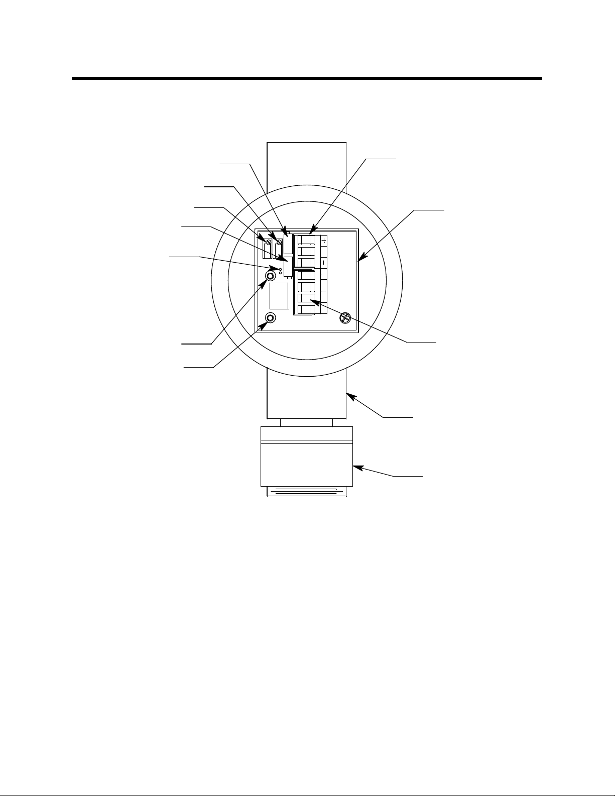
This section describes the components of the CO2 transmitter. The transmitter is a 4 - 20
mA type detector head. It consists of the CO
detector, amplifier, and junction box.
2
Factory Adjust Pot
Span Pot
Ze ro P ot
Factory Adjust Pot
Jumper Pins,
actory UseOnly
+ Test Point
- Test Point
Controller Terminal Strip
Amplifier
SPAN
ZERO
Sensor
Current
mA
S
PWR / SIG
G
LEL
R W B
Detector Termina
Strip
J-Box
IR CO2Detector
Figure 1: CO2 Transmitter Component Location
Infrared CO2 Detector
The CO2 detector consists of the detector housing body, detector housing cap, cap gasket,
and the plug-in sensor.
2 • 65-2397RK CO2 Transmitter
Page 7
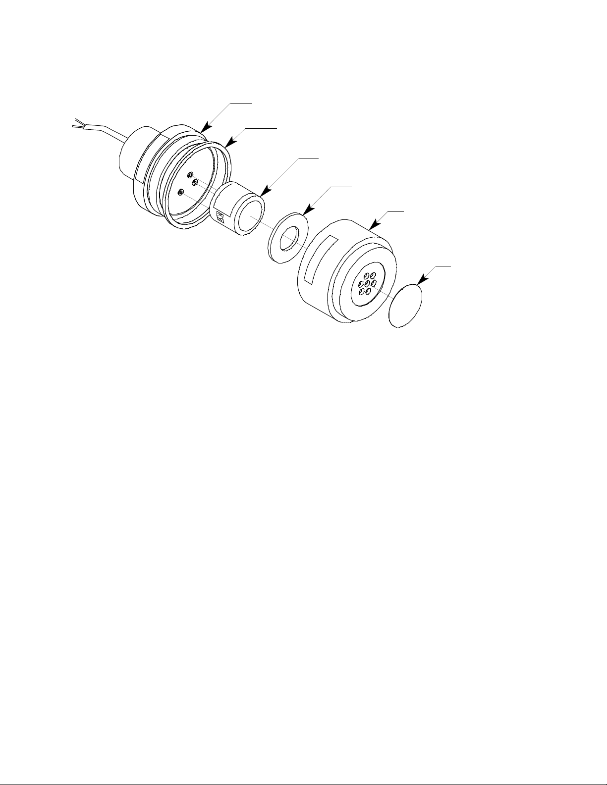
Detector Housing Body
Cap Gasket
Plug-In CO2 Sensor
Sensor Retainer
Detector Housing Cap
Hydrophobic
Membrane
Figure 2: CO2 Detector Component Location
Detector Housing Body
The detector housing body protects the electronic components within the housing. Use the
mounting threads at the top of the housing to screw the CO
hub on the bottom of the junction box. Four color coded leads, red, white, green, and
black, extend from the other end of the detector. The leads allow you to connect the
detector to the amplifier.
The housing includes three sockets installed on a circuit board. These sockets accept the
plug-in sensor’s three pins to provide an electrical connection for the sensor. The circuit
board with the sockets conditions the sensor’s signal before the signal reaches the
amplifier.
Housing Cap & Cap Gasket
The housing cap screws onto the detector housing. It retains the plug-in sensor and
protects it from damage. A foam gasket is installed inside the ho using cap that seals
against the sensor face. A hydrophobic membrane on the outside of the cap face keeps
water and particulates away from the sensor face behind the cap. Unscrew the detector
cap to access the plug-in sensor for maintenance or replacement. A cap gasket seals the
interface between the housing and cap.
Plug-In CO
The plug-in sensor is secured in the detector assembly by the housing cap. The se nsor
produces a millivolt output that corresponds to the detection range of the transmitter.
Sensor
2
detector into the 3/4” NPT
2
Amplifier
The amplifier converts the electrical output from the detector to a 4 to 20 mA signal that
corresponds to the detection range and transmits the signal to a gas monitoring controller .
A foam gasket that orients the amplifier and keeps it from rotating is installed on the
65-2397RK CO2 Transm itter • 3
Page 8

bottom of the amplifier. The amplifier includes the controller terminal strip, detector
terminal strip, span pot, zero pot, and test points (see Figure 1) .
Controller Terminal Strip
The controller terminal strip is a three position plug-in style terminal strip located near the
top of the amplifier. Use the controller terminal strip to wire the CO
transmitter to a
2
controller.
Detector Terminal Strip
The detector terminal strip is a four position plug-in style terminal strip located below the
controller terminal strip. Use the detector terminal strip to connect the CO
transmitter to
2
the amplifier.
NOTE: The IR CO2 detector is factory-wired to the detector terminal strip. See “Wiring
the CO
Transmitter to a Controller” on page 6 for all wiring procedures related
2
to the transmitter.
Zero Pot
The zero pot is located in the upper left corner of the amplifier (see Figure 1). Use a small
flat blade screwdriver to turn the zero pot’s adjustment screw and adjust th e amplifier’s
target gas-free output during the start-up and calibration pr ocedures. Turn the adjustment
screw clockwise to increase the zero output and counterclockwise to decrease the zero
output.
Span Pot
The span pot is located to the right of the zero pot (see Figure 1). Use a small flat blade
screwdriver to turn the span pot’s adjustment screw and adjust the amplifier’s gas
response output during the calibration procedure. Turn the adjustment screw clockwise to
increase the gas response and counterclockwise to decrease the gas response.
CAUTION: The amplifier includes two additional potentiometers. They are factory-set. Do not
adjust them.
Test Points
The test points are on the left side of the amplifier (see Figure 1). The test points produce a
100 mV to 500 mV output that corresponds to the transmitter’s 4 to 20 mA output. Use the
test points and a voltmeter to measure the amplifier’s output during the start-up and
calibration procedures. The black test point in the lower left corner is the negative (-) test
point and the red test point below the zero pot is the positive (+) test point.
Junction Box
Use the junction box to install the transm itter at a mounting site that is remote from the
controller. The junction box protects the amplifier and wiring connections made to the
amplifier. Use the top 3/4’’ conduit hub to connect wiring from the amplifier to the
controller. Use the cover on the front of the junction box to access the interior of the
junction box. The detector and amplifier are factory installed in the junction box. Three
spacers installed on the back of the junction box control the distance of the junction box
from a mounting surface and ensure that there is enough room to install a calibration cup
on the detector during calibration.
4 • 65-2397RK CO2 Transmitter
Page 9

Installation
3.10
This section describes procedures to mount the CO2 transmitter in the monitoring
environment and wire the transmitter to a controller.
Mounting the CO2 Transmitter
1. Select a mounting site that is representative of the monitoring environment. Consider
the following when you select the mounting site.
• Select a site where the transmitter is not likely to be bumped or disturbed. Make
sure there is sufficient room to perform start-up, maintenance, and calibration
procedures.
• Mount the transmitter at least six feet from the floor to minimize the possibility of
someone breathing on the unit. The exhaled CO
may cause an alarm.
2
3/4 NPT
Female
.75
.38
3.65
6.80 MAX
Rubber
Spacers,
3X
J-Box
IR CO2
Detector
1 1/2-2 0 Thre a d for
Calibration Cup
Figure 3: Mounting the CO2 Transmitter
2. At the monitoring site you select, hang or mount th e jun c tion box with the detector
facing down (see Figure 3).
65-2397RK CO2 Transm itter • 5
Page 10

Wiring the CO2 Transmitter to a Controller
WARN ING: Alway s verify that the power to the controller is off before you make
wiring connections.
1. Turn off the controller.
2. Turn off or unplug power to the controller.
3. Remove the junction box cover.
4. The detector leads are factory wired. Verify that the detector leads are wired to the
amplifier’s detector terminal strip as shown in Figure 4.
5. To gain access to a plug-in terminal strip for wiring, pull it out of its sock et by
grasping the terminal strip and pulling. The detecto r strip is keyed so that the
controller and detector terminal strips cannot be reversed inadvertently.
6. Guide a three-conductor, shielded cable, or three wires in conduit through the top
conduit hub of the junction box.
7. Pull out the controller terminal strip, and connect the three wires to the terminal strip
as follows (see Figure 4).
• Connect the positive wire to the PWR/SIG “+” terminal.
• Connect the signal wire to the PWR/SIG “S” terminal.
• Connect the negative wire to the PWR/SIG “-” terminal.
CAUTION: If shielded cable is used, leave the cable shield’s drain wire disconnected and
insulated at the transmitter. You will connect the opposite end of the cable’s drain
wire to the controller’s chassis (earth) ground.
8. Reinstall the controller terminal strip into its socket.
9. Secure the junction box cover to the junction box.
10. Route the cable or wires leading from the CO
transmitter through one of the conduit
2
hubs at the controller housing.
CAUTION: Do not route power and transmitter wiring through the same controller conduit hub.
The power cabl e may disrupt the transmission o f the transmitte r signal to the
controller.
11. Connect the wires to the applicable detector/transmitter termin al strip at the
controller as shown in Figure 4.
6 • 65-2397RK CO2 Transmitter
Page 11
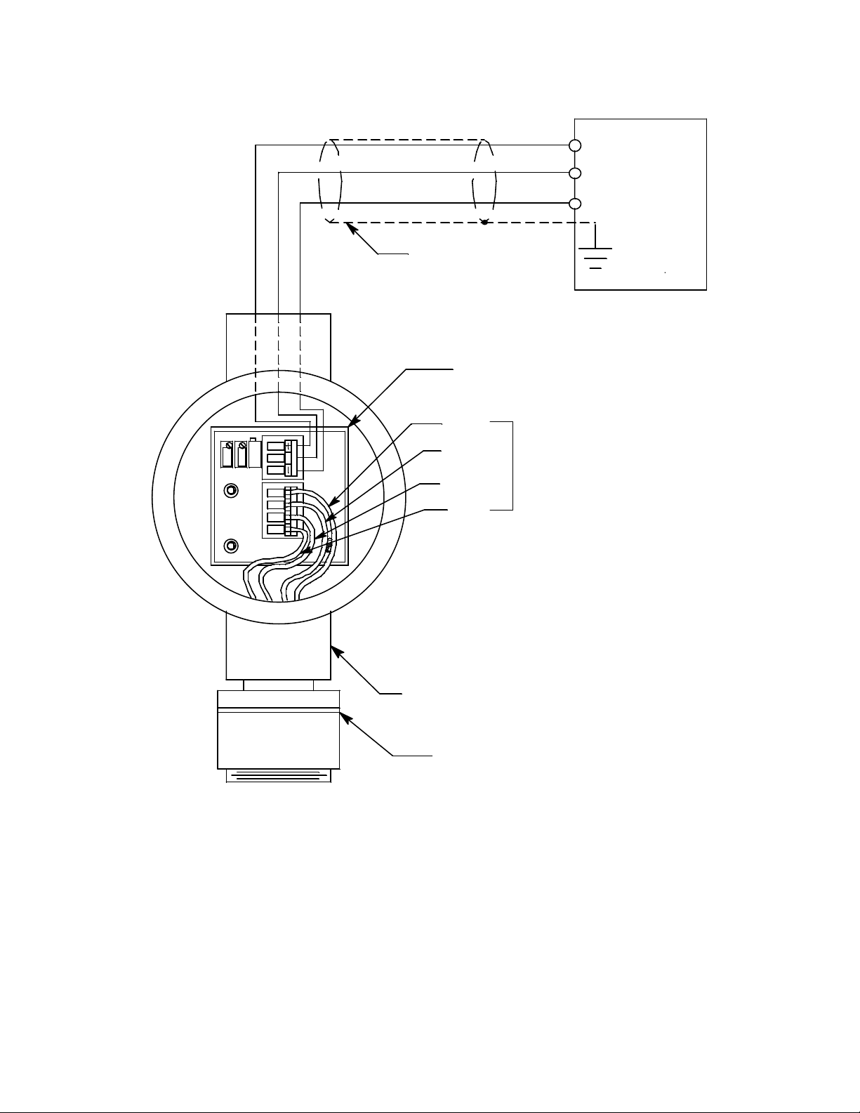
Cable sheild
Amplifier
Black
+ 24 VDC
4 - 20 mA In (S)
- (DC Ground)
Controller
SPAN
ZERO
S
SIG/PWR
BGW
LEL
R
Green
Detector Wires
White
Red
J-Box
IR CO2 Detector
Figure 4: Wiring the CO
12. If shielded cable is used, connect the cable’s drain wire to an available chassis (earth)
ground at the controller. RKI controllers typically have a ground stud that can be used
to ground the cable’s drain wire.
Transmitter to a Controller
2
65-2397RK CO2 Transm itter • 7
Page 12

Start Up
This section describes procedures to start up the CO2 transmitter and place the transmitter
into normal operation.
Introducing Incoming Power
1. Complete the installation procedures described earlier in this manual.
2. Verify that the power wiring to the controller is correct and secure. Refer to the
controller operator’s manual.
3. Turn on power to the controller.
4. Turn on the controller.
5. Verify that the controller is on and operating properly. Refer to the controller
operator’s ma nual.
NOTE: When first powered up, the transmitter will enter about a o ne minute period
when the 4-20 mA output is stab ilizing and may be above the controller alarm
points or well below zero momentarily. RKI controllers have a one minute
warmup period when the controller does not display any gas reading or give any
alarm indication. The CO
time the controller’s warmup period is over.
transmitter’s 4-20 mA signal should be stable by the
2
CAUTION: Allow the detector to warm up for 5 minutes before you continue with the next
section, “Setting the Zero Signal”.
Setting the Zero Signal
Since there is a background of CO2 in air of typically 300 - 600 ppm (0.03 - 0.06 %volume),
it is necessary to use a calibration kit with a 100% nitrogen cylinder to set the zero signal of
a CO
transmitter with a low range detector. Fresh air can be used to zero th e transmitter
2
if a 0-50 %volume or 0-100 %volume detector is being used.
WARN ING: Do not remove the junction box cover while the circuits are energized
unless the area is determined to be non-hazardous. Keep the junction box
cover tightly closed during operation.
The procedure below describes applying 100% nitrogen using a calibration kit that
includes a calibration cup, calibration gas, sample tubing, and a fixed flow regulator with
an on/off knob. RKI Instruments, Inc. recommends using a 0. 5 LPM (liters per minute)
fixed flow regulator.
1. Unscrew and remove the junction box cover from the junction box.
2. Set a voltmeter to measure in the millivolt (mV) range.
3. Plug the voltmeter leads into the test points on the amplifier. Plug the positive lead
into the red (+) test point; plug the negative lead into the black (-) test point.
4. Screw the calibration cup onto the bottom of the IR CO
5. Screw the regulator into the 100% nitrogen calibration cylinder.
6. Use the calibration kit sample tubing to connect the regulator to the calibration cup.
8 • 65-2397RK CO2 Transmitter
detector .
2
Page 13

7. Turn the regulator’s on/off knob counterclockwise to open it. Gas will begin to flow.
8. Allow the gas to flow for one minute.
9. Verify a voltmeter reading of 100 mV (±2 mV).
10. If necessary, use a small flat-blade screwdriver to adjust the zero pot until the
11. Turn the regulator’s on/off knob clockwise to close it.
12. Unscrew the calibration cup from the detector.
13. Unscrew the regulator from the 100% nitrogen calibration cylinder. For convenience,
14. Store th e components of the calibration kit in a safe and convenient place.
15. Remove the voltmeter leads from the test points.
16. Secure the junction box cover to the junction box.
Maintenance
This section describes maintenance procedures. It includes preventive maintenance,
troubleshooting, and component replacement procedures.
voltmeter reading is 100 mV (±2 mV).
leave the sample tubing connected to the regulator and the calibration cup.
Preventive Maintenance
This section describes a preventive maintenance schedule to ensure the optimum
performance of the CO
Daily
Verify a display reading at the controller of the background concentration of CO
background concentrations of CO
depending on location. The 0-5,000 ppm and 0-5 %vol ume detectors will display a r eading
in a fresh air environment because they have low ranges. The 0-50 %volume and 0-100%
volume detectors will not display a reading in fresh air because their ranges are too large.
Investigate significant changes in the display reading.
Monthly
This procedure describes a test to verify that the CO
target gas.
WARN ING: The controller is not an acti ve gas monitoring device during the response
test procedure.
NOTE: Performing a response test on the CO2 transmitter may cause alarms. Be sure to
put the controller into its calibration mode or disable external alarms before
performing this test.
transmitter. It includes daily, monthly, and biannual procedu res.
2
. Typical
2
vary from abou t 300 to 600 ppm ( 0.03 to 0 .06 %volu me)
2
transmitter responds properly to the
2
NOTE: The following procedure assumes the use of a calibration kit which includes a
calibration gas cylinder, a 0.5 LPM fixed flow regulator with an on/off knob, a
calibration cup for the detector, and a length of sample tubing.
65-2397RK CO2 Transm itter • 9
Page 14

Preparing for the response test
1. Place the controller into its calibration mode or disable external alarms.
2. Verify that the controller disp lay reading for the channel you are testing is consistent
with typical background levels of CO
If the display reading is not consistent with typical ba ckgrou nd levels of CO
.
2
, set the
2
zero reading of the transmitter as described in “Start Up” on page 8 of this manual,
then continue this procedure.
3. Screw the regulator into the calibration cylinder.
4. Screw the calibration cup onto the bottom of the detector.
5. Use the calibration kit sample tubing to connect the regulator to the calibration cup.
6. Set a voltmeter to measure in the millivolt (mV) range.
7. Plug the voltmeter leads into the test points on the amplifier. Plug the positive lead
into the red (+) test point; plug the negative lead into the black (-) test point.
8. Use the following formula to determine the correct test points output for the test
sample.
Output (mV) = (calibrating sample/fullscale) X 400 + 100
For example, with a test sample of 2.5 %Vol. and a fullscale setting of 5 %Vol., the
correct output is 300 mV.
300 (mV) = (50/100) X 400 +100
Performing the response test
1. Turn the regulator’s on/off knob counterclockwise to open the regulator. Gas will
begin to flow.
2. Allow the gas to flow for one minute.
3. Verify that the reading is within ± 20% of the response reading you determined earlier.
NOTE: If the reading is not within ± 20% of the correct response reading, calibrate the
transmitter as described in “Calibration” on page 16 of this manual.
4. Turn the regulator’s on/off knob clockwise to close the regulator.
5. Unscrew the regulator from the calibration cylind er.
6. Unscrew the calibration cup from the detector.
NOTE: For convenience, leave the regulator and calibration cup connected by the
sample tubing.
7. Remove the voltmeter leads from the am plifier test points.
8. Reinstall the junction box cover.
9. When the controller display reading falls below th e alarm setpoints, return the
controller to normal operation.
10. Store the components of the calibration kit in a safe place.
Biannually
Calibrate the CO
10 • 65-2397RK CO2 Transmitter
transmitter as described in “Calibration” on page 16 of this manual.
2
Page 15

Troubleshooting
The troubleshooting guide describes symptoms, probable causes, and recommended
action for problems you may encounter with the CO
NOTE: This troubleshooting guide describes transmitter problems only. See the
controller operator’s manual for problems you may encounter with the
controller.
Table 2:Troubleshooting the CO2 Transmitter
Condition Symptom(s) Probable Causes Recommended Action
transmitter.
2
Fail Condition • Controller indicates a
Slow or No
Response/
Difficult or
Unable to
Calibrate
fail condition.
• Transmitter re sponds
slowly or does not
respond to response
test.
• Unable to accurately
set the zero or
response reading
during calibration.
• Transmitter requires
frequent calibration.
Note: Under “normal”
circumstances, the
transmitter requires
calibration once every 6
months.
Some applications
may require a more
frequent calibration
schedule.
• The transmitter wiring
is disconnected or
misconnected.
• The wiring from the
detector to the
amplifier is
disconnected or
misconnected.
• The plug-in sensor is
not properly plugged
into the three-socket
pattern in the detector
housing body.
• The transmitter’s zero
reading is low enough
to cause a fail
condition.
• The transmitter is
malfunctioning.
• The calibration c ylinder
is low, out-dated, or
defective.
• The calibration gas is
not an appr opriate
concentration.
• The membrane on the
detector housing cap is
blocked with dirt or
some other particulate
matter.
• The transmitter is
malfunctioning.
1. Verify that the transmitter wiring to the
controller is correct and secure.
2. Verify that the wiring f rom the detect or
to the amplifier is correct and secure.
3. Confirm that the plug-in sensor is
properly installed.
4. Perform a zero adjustment. A full
calibration is recommended.
5. If the fail condition continues, replace
the sensor as described later in this
section.
6. If the fail condition continues, contact
RKI for further instruction.
1. Verify that the calibration cylinder
contains an adequate supply of a
fresh test sample.
2. Check the face of the detector
housing cap and remove any
particulate contamination from the
hydrophobic membrane if necessary.
3. Verify that the calibration gas
concentration is appropriate for the
transmitter.
4. If the calibration/response difficulties
continue, replace the sensor as
described later in this section.
5. If the calibration/response difficulties
continue, contact RKI for further
instruction.
65-2397RK CO2 Transmitte r • 1 1
Page 16

Replacing Components of the CO2 Transmitter
This section includes a procedure to replace the hydrophobic membrane, a procedure to
replace the plug-in IR CO
assembly, and one to replace the amplifier. In most cases, it is not necessary to replace the
entire detector assembly.
Replacing the Hydrophobic Membrane
1. Turn off the controller.
2. Turn off or unplug incoming power to the controller.
3. Unscrew the detector housing cap from the detector housing body.
4. Gently pry up the edge of the white hydrophobic mem b rane with a small flat blade
screwdriver or a similar tool.
5. Peel off the hydrophobic membrane. It may be necessary to clean off the detector
housing cap face to remove any residue left from the adhesive backed membrane.
6. Install the new membrane in the recess on the face of the detector housing cap.
7. Make sure the cap gasket is in place and screw the detector housing cap back onto the
detector housing body.
8. Turn on the pow e r to the controller.
sensor, a procedure to replace the entire CO2 detector
2
9. Turn on the controller and place it into normal operation.
NOTE: When first powered up, the transmitter will enter about a o ne minute period
when the 4-20 mA output is stab ilizing and may be above the controller alarm
points or well below zero momentarily. RKI controllers have a one minute
warmup period when the controller does not display any gas reading or give any
alarm indication. The combustible gas transmitter’s 4-20 mA signal should be
stable by the time the controller’s warmup period is over.
Replacing the Plug-In CO
Sensor
2
1. Turn off the controller.
2. Turn off or unplug power to the controller.
3. Unscrew the detector housing cap from the detector housing body. Make sure not to
lose the cap gasket.
4. Unplug and remove the plug-in IR CO
sensor.
2
5. Carefully plug the replacement sensor into the socket pattern that is located in the
detector housing.
6. Make sure the cap gasket is in place and screw the detector housing cap back onto the
detector housing body.
7. Turn on power to the controller.
8. Turn on the controller and place it into normal operation.
12 • 65-2397RK CO2 Transmitter
Page 17

NOTE: When first powered up, the transmitter will enter about a o ne minute period
when the 4-20 mA output is stab ilizing and may be above the controller alarm
points or well below zero momentarily. RKI controllers have a one minute
warmup period when the controller does not display any gas reading or give any
alarm indication. The CO
transmitter’s 4-20 mA signal should be stable by the
2
time the controller’s warmup period is over.
CAUTION: Allow the replacement sensor to warm up for 5 minutes before you continue with the
next step.
9. Calibrate the transmitter as described in “Calibration” on page 16.
Replacing the IR CO
Detector
2
NOTE: In most cases it is only necessary to replace the IR CO2 plug-in sensor.
1. Turn off the controller.
2. Turn off or unplug power to the controller.
3. Remove the junction box cover.
4. Remove the detector terminal strip from its socket.
5. Disconnect the detector leads from the detector terminal strip. Note the position of the
color-coded leads as you remove them.
6. Unscrew the detector from the junction box.
7. Guide the detector leads of the replacement detector through the bottom conduit hub
of the junction box, then screw the mounting threads of the detector into the conduit
hub. If necessary for environmental conditions, apply thread sealant or teflon tape to
the hub and/or detector threads to seal them.
8. Connect the detector leads to the detector terminal strip as shown in Table 3 below
and Figure 4 on page 7 of this manual.
Table 3:Reconnecting the CO
Detector to the Amplifier
2
Detector Lead Detector Terminal Strip
Red LEL “R”
White LEL “W”
Green LEL “G”
Black LEL “B”
9. Reinstall the detector terminal strip into its socket.
10. Reinstall the junction box cover.
11. Turn on or plug in power to the controller.
12. Turn on the controller and place it int o normal operation.
65-2397RK CO2 Transmitte r • 1 3
Page 18

NOTE: When first powered up, the transmitter will enter about a o ne minute period
when the 4-20 mA output is stab ilizing and may be above the controller alarm
points or well below zero momentarily. RKI controllers have a one minute
warmup period when the controller does not display any gas reading or give any
alarm indication. The CO
transmitter’s 4-20 mA signal should be stable by the
2
time the controller’s warmup period is over.
CAUTION: Allow the replacemen t detector to warm up for 5 minutes before you continue with
the next step.
13. Calibrate the transmitter as described in “Calibration” on page 16 of this manual.
Replacing the Amplifier
1. Turn off the controller.
2. Turn off or unplug power to the controller.
3. Remove the junction box cover.
4. Unplug the detector terminal strip and controller terminal strip from their sockets.
You may leave the wires connected to the terminal strips.
5. Unscrew and remove the screw with the flat and lock washers that secures the
amplifier to the junction box.
6. Remove the old amplifier.
7. Place the new amplifier in the same position as the old amplifier. A foam gasket that
orients the amplifier and keeps it from rotating is installed on the bottom of the
amplifier. Make sure the amplifier is seated flat in the junction box.
8. Install the new amplifier in to the junction box with the screw, lock washer, and flat
washer you removed in Step 5 above.
9. Install the detector and controller terminal strips into their socket s on the new
amplifier as shown in Figure 4 on page 7 of this manual. If controller leads or detector
leads were removed d uring this procedure, refer to Table 4 and Table 5 b elow.
Table 4:Reconnecting the Amplifier
to the Controller
Amplifier Controller
Terminal Strip
PWR/SIG “-” - (DC -)
PWR/SIG “S” S (4 - 20 mA In)
PWR/SIG “+” + 24V
Table 5:Reconnecting the CO
Detector to the Amplifier
Controller
Transm itte r Terminal
Strip (typical)
2
14 • 65-2397RK CO2 Transmitter
Amplifier Detector
T erminal Strip
DETECTOR “R” RED
Detector Lead
Page 19

Table 5:Reconnecting the CO
Detector to the Amplifier
Amplifier Detector
T erminal Strip
DETECTOR “W” WHT
DETECTOR “G” GREEN
DETECTOR “B” BLK
Detector Lead
2
NOTE: When a transmitter is first powered up with a new amplifier, the initial output
may be either high or below zero depending on the setting of the zero pot. Be
sure to make arrangements so that this does not cause unwanted alarms.
10. Turn on power to the controller.
11. Turn on the controller and place it int o normal operation.
NOTE: When first powered up, the transmitter will enter about a o ne minute period
when the 4-20 mA output is stab ilizing and may be above the controller alarm
points or well below zero momentarily. RKI controllers have a one minute
warmup period when the controller does not display any gas reading or give any
alarm indication. The CO
transmitter’s 4-20 mA signal should be stable by the
2
time the controller’s warmup period is over.
12. Allow the transmitter to warm-up for 5 minutes.
13. Calibrate the transmitter as described in “Calibration” on page 16 of this manual.
Calibration Frequency
Although there is no particular calibration frequency that is correct for all applications, a
calibration frequency of every 6 months is adequate for most infrared CO
applications. Unless experience in a particular application dictates otherwise, RKI
Instruments, Inc. recommends a calibration frequency of every 6 months.
If an application is not very demanding, for example detection in a clean, temperature
controlled environment where calibration adjustments are minimal at calibration, then a
calibration frequency of every 9 to 12 months is adequate.
If an application is very demanding, for example if the environment is not well controlled,
then more frequent calibration than every 6 months may be necessary.
transmitter
2
65-2397RK CO2 Transmitte r • 1 5
Page 20

Calibration
This section describes how to calibrate the CO2 transmitter. It includes procedures to
prepare for calibration, set the zero reading, set the response rea d ing, and return to
normal operation.
W ARNING: The controller is not an active gas monitoring device during the calibration
procedure.
NOTE: The following procedure assumes the use of a calibration kit which includes a
calibration gas cylinder, a 100% nitrogen cylinder, a 0.5 LPM fixed flow regulator
with an on/off knob, a calibration cup for the detector, and a short piece of
sample tubing to connect the regulator to the calibration cup.
Prepari ng for Ca libration
1. Unscrew and remove the junction box cover.
2. Set a voltmeter to measure in the millivolt (mV) range.
3. Plug the voltmeter leads into the test points on the amplifier. Plug the positive lead
into the red (+) test point; plug the negative lead into the black (-) test point.
4. Use the following formula to determine the correct test points output for the
calibrating sample.
Output (mV) = (calibrating sample/fullscale) X 400 + 100
For example, with a calibrating sample of 2.5 %Vol. and a fullscale setting of
5 %Vol., the correct output is 300 mV.
300(mV) = (50/100) X 400 +100
5. Screw the calibration cup onto the detector housing.
6. Place the controller into its calibration mode or disable external alarms.
NOTE: Calibrating the CO2 transmitter may cause alarms. Be sure to put the controller
into its calibration mode or disable external alarms before continuing.
Setting the Zero Reading
Since there is a background of CO2 in air of typically 300 - 600 ppm (0.03 - 0.06 %volume),
it is necessary to use a calibration kit with a 100% nitrogen cylinder to set the zero signal of
a CO
transmitter with a low range detector. Fresh air can be used to zero th e transmitter
2
if a 0-50 %volume or 0-100 %volume detector is being used.
1. Screw the regulator into the 100% nitrogen calibration cylinder.
2. Use the calibration kit sample tubing to connect the regulator to the calibration cup.
3. Turn the regulator’s on/off knob counterclockwise to open the regulator.
4. Allow the gas to flow for one minute and verify a reading of 100 mV (±2 mV). If
necessary, use the zero pot on the amplifier to adjust the reading to 100 mV (±2 mV).
5. Turn the regulator’s on/off knob clockwise to close the regulator.
16 • 65-2397RK CO2 Transmitter
Page 21

6. Unscrew the regulator from the zero air calibration cylinder.
7. Leave the sample tubing connected to the regulator and the calibration cup.
Setting the Response Reading
1. Screw the regulator into the calibration cylinder. Verify that the calibration gas is
representative of the transmitter’s target gas.
2. Turn the regulator’s on/off knob counterclockwise to open the regulator.
3. Allow the calibration gas to flow for one minute and verify that the reading matches
the response reading (±2 mV) you determined ea rlier. If necessary , use the span pot on
the amplifier to adjust the reading to match the correct response reading.
4. Turn the regulator’s on/off knob clockwise to close the regulator.
5. Unscrew the regulator from the calibration cylind er.
Returning to Normal Operation
1. Remove the voltmeter leads from the am plifier test points.
2. Unscrew the calibration cup from the detector.
NOTE: For convenience, leave the regulator and calibration cup connected by the
sample tubing.
3. Secure the junction box cover to the junction box.
4. When the controller display reading falls below th e alarm setpoints, return the
controller to normal operation.
5. Verify that the co ntroller display reading decreases and stabilizes at a typical
background CO
reading in a fresh air environment because they have low ranges. The 0-50 %volume
and 0-100 %volume detectors will not display a reading in fresh air because their
ranges are too large.
6. Store the components of the calibration kit in a safe and convenient place.
level. The 0-5,000 ppm and 0-5 %volume detectors will display a
2
65-2397RK CO2 Transmitte r • 1 7
Page 22

Parts List
Part Number Description
06-1248RK Sample tubing (3/16 in. x 5/16 in.; specify length when ordering )
07-0039RK Detector housing cap gasket
18-0400RK-01 Junction box with spacers
33-0157RK Hydrophobic disk membrane for detector cap
57-1053RK Amplifier with gasket (specify detector part number when ordering)
Table 6 lists replacement parts and accessories for the CO2 transmitter.
Ta ble 6: Par ts List
61-5040RK-02 CO
61-5040RK-03 CO
61-5040RK-05 CO
61-5040RK-10 CO
65-2397RK-02 CO
65-2397RK-03 CO
65-2397RK-05 CO
65-2397RK-10 CO
71-0185RK 65-2397RK CO
81-0070RK-01 Steel calibration cylinder, 2000 ppm CO
81-0072RK-01 Steel calibration cylinder, 2.5% CO
81-0073RK-01 Steel calibration cylinder, 15% CO
replacement plug-in sensor, 0-5,000 ppm
2
replacement plug-in sensor, 0-5% Volume
2
replacement plug-in sensor, 0-50% Volume
2
replacement plug-in sensor, 0-100% Volume
2
transmitter, 0-5000 ppm, (includes detector, junction box, and amplifier)
2
transmitter, 0-5% V ol ume, (inc lud es detec tor, junction box, and amplifier)
2
transmitter, 0-50% Volume, (includes detector, junction box, and amplifier)
2
transmitter, 0-100% Volume, (includes detector, junction box, and amplifier)
2
Transmitter Operator’s Manual (this document)
2
, 34-liter
2
, 34-liter
2
, 34-liter
2
81-0078RK-01 Steel calibration cylinder, 100% nitrogen, 34-liter
81-1050RK Regulator, 0.5 liter/minute; with pressure gauge and flow control knob, for 17 liter
and 34 liter steel calibration cy lin der s
81-1117RK Calibration cup
82-0006RK Pot adjust screwdriver, for calibration
18 • 65-2397RK CO2 Transmitter
 Loading...