

Page 1

65-2391RK
CO2 Transmitter
Operator’s Manual
Part Number: 71-0121RK
Revision: B
Released: 7/18/14
www.rkiinstruments.com
Page 2

WARNING
Read and understand this instruction manual before
operating transmitter. Improper use of the transmitter could
result in bodily harm or death.
Periodic calibration and maintenance of the transmitter is
essential for proper operation and correct readings. Please
calibrate and maintain this tra nsmitt er regula rly! Frequency
of calibration depends upon the type of use you have and
the sensor types. Typical calibration frequencies for most
applications are between 6 and 12 months, but can be
required more often or less often based on your usage.
65-2391RK CO2 Transmitter
Page 3

Product Warranty
RKI Instruments, Inc., warrants gas alarm equipment sold by us to be free from defects in
materials, workmanship, and performance for a period of one year fr o m date of shipment
from RKI Instruments, Inc. Any parts found defective withi n tha t period will be repaired
or replaced, at our option, free of charge. This warranty does not apply to those items
which by their nature are subject to deterioration or consumption in normal ser v ice, and
which must be cleaned, repaired, or replaced on a routine basis. Examples of such items
are:
W arranty is voided by abuse including mechanical damage, alteration, rough handling, or
repair procedures not in accordance with the operator’s manual. This warranty indicates
the full extent of our liability , a nd we are not r esponsible for removal or r eplacement costs,
local repair costs, transportation costs, or contingent expenses incurred without our prior
approval.
a) Absorbent cartridges d) Batteries
b) Pump diaphragms and valves e) Filter elements
c) Fuses
THIS WARRANTY IS EXPRESSLY IN LIEU OF ANY AND ALL OTHER
WARRANTIES AND REPRESENTATIONS, EXPRESSED OR IMPLIED,
AND ALL OTHER OBLIGATIONS OR LIABILITIES ON THE PART OF
RKI INSTRUMENTS, INC. INCLUDING BUT NOT LIMITED TO, THE
WARRANTY OF MERCHANTABILITY OR FITNESS FOR A
PARTICULAR PURPOSE. IN NO EVENT SHALL RK I INSTRUMENTS,
INC. BE LIABLE FOR INDIRECT, INCIDENTAL, OR CONSEQUENTIAL
LOSS OR DAMAGE OF ANY KIND CONNECTED WITH THE USE OF
ITS PRODUCTS OR FAILURE OF ITS PRODUCTS TO FUNCTION OR
OPERATE PROPERLY.
This warranty covers instruments and parts sold to users by authorized distributors,
dealers, and representatives as appointed by RKI Instruments, Inc.
We do not assume i ndemnification for any accident or dama g e c au s e d by the operation of
this gas monitor, and our warranty is limited to the replacement of parts or our complete
goods.
65-2391RK CO2 Transmitter
Page 4

Table of Contents
Overview . . . . . . . . . . . . . . . . . . . . . . . . . . . . . . . . . . . . . . . . . . . . . . . . . . . . . . . . . . . . . . . . . . . 1
Specifications. . . . . . . . . . . . . . . . . . . . . . . . . . . . . . . . . . . . . . . . . . . . . . . . . . . . . . . . . . . . . . . . 1
Description. . . . . . . . . . . . . . . . . . . . . . . . . . . . . . . . . . . . . . . . . . . . . . . . . . . . . . . . . . . . . . . . . . 2
IR CO2 Detector. . . . . . . . . . . . . . . . . . . . . . . . . . . . . . . . . . . . . . . . . . . . . . . . . . . . . . . . . . . . . . . . . . . . . . . 2
Amplifier . . . . . . . . . . . . . . . . . . . . . . . . . . . . . . . . . . . . . . . . . . . . . . . . . . . . . . . . . . . . . . . . . . . . . . . . . . . . 3
Junction Box. . . . . . . . . . . . . . . . . . . . . . . . . . . . . . . . . . . . . . . . . . . . . . . . . . . . . . . . . . . . . . . . . . . . . . . . . . 4
Installation . . . . . . . . . . . . . . . . . . . . . . . . . . . . . . . . . . . . . . . . . . . . . . . . . . . . . . . . . . . . . . . . . . 4
Mounting the CO2 Transmitter. . . . . . . . . . . . . . . . . . . . . . . . . . . . . . . . . . . . . . . . . . . . . . . . . . . . . . . . . . 4
Wiring the CO
Startup. . . . . . . . . . . . . . . . . . . . . . . . . . . . . . . . . . . . . . . . . . . . . . . . . . . . . . . . . . . . . . . . . . . . . . 6
Transmitter . . . . . . . . . . . . . . . . . . . . . . . . . . . . . . . . . . . . . . . . . . . . . . . . . . . . . . . . . . . . 5
2
Introducing Incoming Power . . . . . . . . . . . . . . . . . . . . . . . . . . . . . . . . . . . . . . . . . . . . . . . . . . . . . . . . . . . 6
Setting the Zero Signal. . . . . . . . . . . . . . . . . . . . . . . . . . . . . . . . . . . . . . . . . . . . . . . . . . . . . . . . . . . . . . . . . 7
Maintenance. . . . . . . . . . . . . . . . . . . . . . . . . . . . . . . . . . . . . . . . . . . . . . . . . . . . . . . . . . . . . . . . . 8
Preventive Maintenance . . . . . . . . . . . . . . . . . . . . . . . . . . . . . . . . . . . . . . . . . . . . . . . . . . . . . . . . . . . . . . . 8
Troubleshooting . . . . . . . . . . . . . . . . . . . . . . . . . . . . . . . . . . . . . . . . . . . . . . . . . . . . . . . . . . . . . . . . . . . . . 10
Replacing Components of the CO
Transmitter. . . . . . . . . . . . . . . . . . . . . . . . . . . . . . . . . . . . . . . . . . . 11
2
Calibration Frequency . . . . . . . . . . . . . . . . . . . . . . . . . . . . . . . . . . . . . . . . . . . . . . . . . . . . . . . 13
Calibration . . . . . . . . . . . . . . . . . . . . . . . . . . . . . . . . . . . . . . . . . . . . . . . . . . . . . . . . . . . . . . . . . 13
Preparing for Calibration. . . . . . . . . . . . . . . . . . . . . . . . . . . . . . . . . . . . . . . . . . . . . . . . . . . . . . . . . . . . . . 13
Setting the Zero Reading. . . . . . . . . . . . . . . . . . . . . . . . . . . . . . . . . . . . . . . . . . . . . . . . . . . . . . . . . . . . . . 14
Setting the Response Reading. . . . . . . . . . . . . . . . . . . . . . . . . . . . . . . . . . . . . . . . . . . . . . . . . . . . . . . . . . 14
Returning to Normal Operation. . . . . . . . . . . . . . . . . . . . . . . . . . . . . . . . . . . . . . . . . . . . . . . . . . . . . . . . 15
Parts List . . . . . . . . . . . . . . . . . . . . . . . . . . . . . . . . . . . . . . . . . . . . . . . . . . . . . . . . . . . . . . . . . . . 15
65-2391RK CO2 Transmitter
Page 5

Overview
This manual describes t he 65 -23 91R K CO2 transmitter. This manual also des c ribes ho w t o
install, start up, configure, maintain, and calibrate the transmitter when it is used with a
gas monitoring controller. A parts list at the end of this manual lists replacement parts and
accessories for the CO
Specifications
Table 1 lists specifications for the CO2 transmitter.
transmitter.
2
Table 1:Specifications
Target/Calibration Gas Carbon Dioxide (CO
Area Classification Explosionproof for Cl ass I, Groups B, C, and D
Sampling Method Diffusion
Signal Output 4 to 20 mA
Detection Range 65-2391RK-02: 0 - 5,000 ppm
65-2391RK-03: 0 - 5% Volume
65-2391RK-05: 0 - 50% Volume
65-2391RK-10: 0 - 100% Volume
Response Time 90% in 45 seconds
Accuracy ± 5% of reading or ± 2% of full scale (whichever is gr eater)
)
2
W ARNING: When using the 65-2391RK, you must follow the instructions and warnings
in this manual to assure proper and safe operation of the 65-2391RK and to
minimize the risk of personal injury. Be sure to maintain and period ically
calibrate the 65-2391RK as described in t hi s manual.
65-2391RK CO2 Transmitter • 1
Page 6
Description
t
ip
S
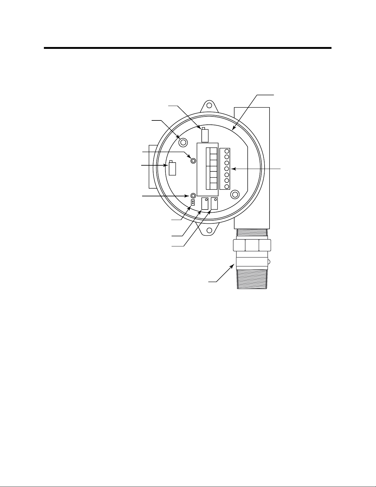
This section describes the components of the CO2 transmitter. The transmitter is a 4 - 20
mA type detector head. It consists of the infrared CO
detector, amplifier, and junction
2
box.
Amplifier
Potentiometer
(factory set)
ecuring screw (2)
Test point (+)
Potentiometer
(factory set)
Test point (-)
GND
24V
TP+
4-20
RED
WHT
GRN
SENSOR POWER/SIG
BLK
TP-
Interconnec
terminal str
Jumper pins
(factory use only)
Span potentiometer
Zero potentiometer
IR CO Detector
2
Figure 1: CO2 Transmitter Component Location
Infrared CO2 Detector
The infrared CO2 detector is made up of a miniature infrared CO2 detector housed and
encapsulated in a pipe nipple. The pipe nipple has 3/4 inch NPT threads on each end and
a 1 1/4 inch hex that allows removal or installation of the detector with a wrench. A
porous flame arrestor that is coated with a hydrophobic film tha t repels liquids is on one
end of the detector and allows sample gas to enter the detector. Four color coded leads,
red, white, green, and black, extend from the other end of the detector. The leads allow
you to connect the detector to the amplifier.
To distinguish the different ranges of CO
shrink tubing is applied to the wiring where it comes out of the nipple. The following
table indicates the color of the shrink tubing and the color of the wire to which it is
applied.
detectors from one another, a short length of
2
2 • 65-2391RK CO2 Transmitter
Page 7

Table 2: CO
Detector Color Designations
2
Detector Color Desig n ations
0 - 5,000 ppm black shrink tubing on white wire
0 - 5% volume green shrink tubing on white wire
0 - 50% volume green shrink tu bing on red wire
0 - 100% volume red shrink tubing on green wire
Amplifier
The amplifier converts the electrical output from the detector to a 4 to 20 mA signal that
corresponds to the detection range and transmits the signal to a gas monitoring controller .
The amplifier includes the interconnect terminal strip, span potentiometer, zero
potentiometer, and test points (see Figure 1).
Interconnect Terminal Strip
The interconnect terminal strip is a seven-point terminal strip. Use the interconnect
terminal strip to connect the IR CO
controller.
NOTE: The IR CO2 detector is factory-wired to the amplifier. See the Installation section
of this manual for all wiring procedures related to the transmitter.
detector to the amplifier and the amplifier to a
2
Span Potentiomete r
The span potentiometer is near the bottom of the amplifier (see Figure 1). Use the span
potentiometer to adjust the transmitter’s response out put during the calibration
procedure. Turn the adjustment screw clockwise to increase the gas respo ns e and
counterclockwise to decrease the gas response.
Zero Potentiometer
The zero potentiometer is to the right of the span potentiometer (see Figure 1). Use the
zero potentiometer to adjust the transmitter’s target gas-free output during the start-up
and calibration procedures. Turn the adjustment screw clockwise to increase the zero
output and counterclockwise to decrease the zero output.
CAUTION: The amplifier includes two additional potentiometers. They are factory-set. Do not
adjust them.
Test Points
The test points (labeled TP+ and TP-) are to the left of the interconnect terminal strip
(see Figure 1). The test points produce a 100 to 500 mV output that corresponds to the
transmitter’s 4 to 20 mA output. Use the test points and a voltme ter to mea sure the
transmitter’s output during the start-up and calibrat ion procedures.
65-2391RK CO2 Transmitter • 3
Page 8

Junction Box
1
g
it
b
Use the junction box to install the CO2 transmitter at a mounting site that is remote from
the controller. The junction box also protects the amplifier and wiring connections made
to the amplifier. Use the two 3/4 in. conduit hubs to mount the detector to the junction
box (bottom hub) and connect wiring from the amplifier to the controller (top hub).
NOTE: The detector and amplifier are factory-mounted to the junction box.
Installation
Use the junction box’s two mounting holes to mount the CO
transmitter to a vertical
2
surface at the monitoring site. Use the cover on the front of the junction box to access the
interior of the junct ion box.
This section describes procedures to mount the CO2 transmitter in the monitoring
environment and wire the transmitter to a controller.
Mounting the CO2 Transmitter
1. Select a mounting site that is representative of the monitoring environment. Consider
the following when you select the mounting site.
• Select a site where the transmitter is not likely to be bumped or disturbed.
• Select a site where there is sufficient room to perform start-up, maintenance, and
calibration procedures.
• Mount the transmitter at least six feet from the floor to minimize the possibility of
someone breathing on the unit. The exhaled CO
5.20
3.94
2.75
may cause an alarm.
2
.25 Dia. Mountin
Hole, 2X
3/4 NPT Condu
Hu
6.10
3/4 NPT For
Calibration Cup
.10
4 • 65-2391RK CO2 Transmitter
5.46
NOTE: All Dimensions in Inches
Figure 2: Mounting the CO2 Transmitter
7.3 Max
1.9
Max
Page 9

If the detector is mounted to the junction box, skip to step 5. If not, continue with step 2.
2. Remove the junction box cover.
3. Guide the four wires that extend from the top of the detector through the bottom
conduit hub of the junction box.
4. Screw the detector into the bottom conduit hub of the junction box.
5. At the monitoring site, use #10 screws through the junction box’s two mounting holes
to secure the junction box to a vertical surface.
CAUTION: Mount the CO2 transmitter with the detector facing down (see Figure 2.)
Wiring the CO2 Transmitter to a Controller
WARN IN G: Always verify that the power to the controller is off before you make
wiring connections.
1. Turn off power to the controller.
2. Place the controller’s power switch in the OFF position.
3. Remove the junction box cover.
4. Verify that the detector leads are wired to the amplifier’s interconnect terminal strip.
If necessary, connect the detector leads to the interconnect terminal s trip as shown in
Figure 3.
5. Guide a three-conductor, s hielded cable or three wires in conduit through the top
conduit hub of the junction box.
6. Connect the three wires to the interconnect terminal strip as follows (see Figure 3).
• Connect the positive wire to the 24VDC terminal.
• Connect the feedback wire to the 4-20 (FB) terminal.
• Connect the negative wire to the GND (DC -) terminal.
CAUTION: If shielded cable is used, leave the cable s hie ld’s drain wire insulated and
disconnected at the transmitter. You will connect the opposite end of the cable’s drain
wire at the controller to chassis ground.
7. Secure the junction box cover to the junction box.
8. Route the cable or wires leading from the CO
transmitter through one of the conduit
2
hubs at the controller housing.
CAUTION: Do not route power and transmitter wiring through the same conduit hub. The
power cable may disrupt the transmission of the transmitter signa l to the
controller.
65-2391RK CO2 Transmitter • 5
Page 10

9. Connect the wires to the applicable transmitter terminal strip at the controller as
r
)
shown in Figure 3 below.
- (DC -)
+ 24 VDC
4 - 20 mA In (FB or S
Cable Shield
Controller Transmitte
GND
24V
TP+
4-20
RED
WHT
GRN
SENSOR POWER/SIG
BLK
TP-
Black
Green
White
Red
Figure 3: Wiring the CO2 Transmitter to a Controller
10. If shielded cable is used, connect the cable’s drain wire to an available chassis ground
at the controller.
Terminals,Typical
Start Up
This section describes procedures to start up the CO2 transmitter and place the transmitter
into normal operation.
Introducing Incoming Power
1. Complete the installation procedures described earlier in this manual.
2. Verify that the power wiring to the controller is correct and secure. Refer to the
controller operator’s manual.
3. Turn on or plug in power to the controller, then place the controller’s power switch in
the ON position.
4. Verify that the controller is on and operating properly. Refer to the controller
operator’s ma nual.
6 • 65-2391RK CO2 Transmitter
Page 11

NOTE: When first powered up, the transmitter will enter about a one minute period
when the 4-20 mA output is stab ilizing and may be above the controller alarm
points or well below zero momentarily. RKI controllers have a one minute
warmup period when the controller does not display any gas reading or give any
alarm indication. The CO
transmitter’s 4-20 mA signal should be stable by the
2
time the controller’s warmup period is over.
CAUTION: Allow the detector to warm up for 5 minutes before you continue with the next
section, “Setting the Zero Signal”.
Setting the Zero Signal
Since there is a background of CO2 in air of typically 300 - 600 ppm (0.03 - 0.06 %volume),
it is necessary to use a calibration kit with a 100% nitrogen cylinder to set the zero signal of
a CO
transmitter with a low range detector. Fresh air can be used to zero the transmitter
2
if a 0-50 %volume or 0-100 %volume detector is being used.
NOTE: The following procedure assumes the use of a calibration kit which includes a
100% nitrogen calibration gas cylinder, a 0.5 LPM fixed flow regulator with an
on/off knob, a calibration cup for the detector, and a short piece of sample tubing
to connect the regulator to the calibration cup.
1. Place the controller into its calibration program or disable external alarms to avoid
accidental alarms during the zero setting procedure.
2. Screw the calibration cup onto the bottom of the detector.
3. Use the sample tubing that comes with the calibration kit to connect the regulator to
the calibration cup.
4. Set a voltmeter to measure in the millivolt (mV) range.
5. Remove the junction box cover, then plug the voltmeter leads into the test points on
the amplifier.
Plug the positive lead into the test point labeled TP+; plug the negative lead into the
test point labeled TP-.
6. Screw the regulator into the 100% nitrogen calibration cylinder.
7. Turn the regulator knob counterclockwise to open the regulator.
8. Allow the gas to flow for one minute and verify a reading of 100 mV (±2 mV). If
necessary, use the zero potentiometer on the amplifier to adjust the reading to 100 mV
(±2 mV).
9. Turn the regulator knob clockwise to close the regulator.
10. Unscrew the regulator from the 100% nitrogen calibration cylinder.
11. Unscrew the calibration cup from the detector.
12. Reinstall the junction box cover.
13. Return the controller to normal operation or enable external alarms.
65-2391RK CO2 Transmitter • 7
Page 12

Maintenance
This section describes maintenance procedures. It includes preventive maintenance,
troubleshooting, and component replacement procedures.
Preventive Maintenance
This section describes a preventive maintenance schedule to ensure the optimum
performance of the CO
Daily
transmitter. It includes daily, monthly, and biannual procedures.
2
Verify a display reading at the controller of the background concentration of CO
background concentrations of CO
vary from abou t 300 to 600 ppm ( 0.03 to 0 .06 %volu me)
2
. Typical
2
depending on location. The 0-5,000 ppm and 0-5 %vol ume detectors will display a r eading
in a fresh air environment because they have low ranges. The 0-50 %volume and 0-100%
volume detectors will not display a reading in fresh air because their ranges are too large.
Investigate significant changes in the display reading.
Monthly
This procedure describes a test to verify that the CO
transmitter responds properly to the
2
target gas.
WARNING: The controller is not an active gas monitoring device during the response
test procedure.
NOTE: Performing a response te st on the CO2 transmitter may cause alarms. Be sure to
put the controller into its calibration program or disable external alarms before
performing this test.
NOTE: The following procedure assumes the use of a calibration kit which includes a
calibration gas cylinder, a 0.5 LPM fixed flow regulator with an on/off knob, a
calibration cup for the detector, and a short piece of sample tubing to connect the
regulator to the calibration cup.
Preparing for the response test
1. Place the controller into its calibration program or disable external alarms.
2. Verify that the controller display reading for the channel you are testing is consistent
with typical background levels of CO
If the display reading is not consistent with typical ba ckgrou nd levels of CO
zero readin g of the transmitter as described in “Start Up” on page6 of this manual,
then continue this procedure.
3. Screw the calibration cup onto the bottom of the detector.
4. Use the calibration kit sample tubing to connect the regulator to the calibration cup.
5. Set a voltmeter to measure in the millivolt (mV) range.
6. Remove the junction box cover, then plug the voltmeter leads into the test points on
the amplifier.
Plug the positive lead into the test point labeled TP+; plug the negative lead into the
8 • 65-2391RK CO2 Transmitter
.
2
, set the
2
Page 13

test point labeled TP-.
7. Use the following formula to determine the correct test points output for the test
sample.
Output (mV) = (calibrating sam ple/fullscale) X 400 + 100
For example, with a test sample of 2.5% CO
and a fullscale setting of 5% CO2, the
2
correct output is 300 mV.
300 (mV) = (2.5/5) X 400 +100
Performing the response test
1. Screw the regulator into the calibration cylinder.
2. Turn the regulator knob counterclockwise to open the regulator.
3. Allow the gas to flow for one minute.
4. Verify that the reading is within ± 20% of the response reading you determined earlier.
NOTE: If the reading is not within ± 20% of the correct response reading, calibrate the
transmitter as described in “Calibration” on page 13 of this manual.
5. Turn the regulator knob clockwise to close the regulator.
6. Unscrew the regulator from the calibration cylind er.
7. Unscrew the calibration cup from the detector.
8. Remove the voltmeter leads from the amplifier test points.
9. Reinstall the junction box cover.
10. When the controller display reading falls below the alarm setpoints, return the
controller to normal operation.
11. Store the components of the calibration kit in a safe place.
Biannually
Calibrate the CO
transmitter as described in “Calibration” on page 13 of this manual.
2
65-2391RK CO2 Transmitter • 9
Page 14

Troubleshooting
The troubleshooting guide describes symptoms, probable causes, and recommended
action for problems you may encounter with the CO
NOTE: This troubleshooting guide describes transmitter problems only. See the
controller operator’s manual for problems you may encounter with the
controller.
Table 3:Troubleshooting the CO2 Transmitter
Condition Symptom(s) Probable Causes Recommended Action
transmitter.
2
Fail Condition • Controller indicates a
Slow or No
Response/
Difficult or
Unable to
Calibrate
fail condition.
• Transmitter responds
slowly or does not
respond to response
test.
• Unable to accurately
set the zero or
response reading
during calibration.
• Transmitter requires
frequent calibration.
Note: Under “normal”
circumstances, the
transmitter requires
calibration once every
six months.
Some applications
may require a more
frequent calibration
schedule.
• The transmitter wiring
is disconnected or
misconnected.
• The transmitter’s
reading in air is low
enough to cause a fail
condition.
• The transmitter is
malfunctioning.
• The calibration cylinder
is low, out-dated, or
defective.
• The transmitter is
malfunctioning.
1. Verify that the transmitter wiring is
correct and secure.
2. Calibrate the transm itt er.
3. If the fail condition continues, replace
the detector.
4. If the fail condition continues, contact
RKI for further instruction.
1. Verify that the calibration cylinder
contains an adequate supply of a
fresh test sample.
2. Verify that the regulator used for
calibration is a 0.5 LPM regulator.
3. If the calibration/response difficulties
continue, replace the detector.
4. If the calibration/response difficulties
continue, contact RKI for further
instruction.
10 • 65-2391RK CO2 Transmitter
Page 15

Replacing Components of the CO2 Transmitter
This section includes procedures to replace the IR CO2 detector and amplifier.
Replacing the IR CO
Detector
2
1. Turn off power to the controller.
2. Place the controller’s power switch in the OFF position.
3. Remove the junction box cover.
4. Disconnect the detector leads from the interconnect terminal strip. Note the posit ion
of the color-coded leads as you remove them.
5. Unscrew the detector from the junction box.
6. Guide the detector leads of the replacement detector through the bottom conduit hub
of the junction box, then screw the mounting threads of the detector into the conduit
hub.
7. Connect the detector leads to the interconnect terminal strip as shown in Table 4
below and Figure 3 on page 6 of th is manual.
Table 4: Reconnecting the CO2
Detector to the Amplifier
Detector Lead
Red RED
White WHT
Amplifier Interconnect
Terminal Strip
Green GRN
Black BLK
8. Turn on pow er to the controller.
9. Place the controller’s power switch in the ON position.
NOTE: When first powered up, the transmitter will enter about a one minute period
when the 4-20 mA output is stab ilizing and may be above the controller alarm
points or well below zero momentarily. RKI controllers have a one minute
warmup period when the controller does not display any gas reading or give any
alarm indication. The CO
transmitter’s 4-20 mA signal should be stable by the
2
time the controller’s warmup period is over.
CAUTION: Allow the replacement detector to warm up for 5 minutes before you co ntinue with
the next step.
10. Calibrate the replacement detector as described in “Calibration” on page 13 of this
manual.
Replacing the Amplifier
1. Turn off power to the controller
2. Place the controller’s power switch in the OFF position.
65-2391RK CO2 Transmitte r • 1 1
Page 16

3. Remove the junction box cover.
4. Disconnect the detector leads from the interconnect terminal strip.
5. Disconnect the wiring that connects the CO
transmitter to the controller from the
2
amplifier’s interconnect terminal strip.
6. Unscrew and remove the two screws that secure the amplifier to the junction box.
The screws are at the top left and bottom right of the amplifier.
7. Remove the amplifier.
8. Place the new amplifier in the same position as the amplifier you removed in the
previous step.
9. Use the two screws you removed in step 6 to secure the amplifier to the junction box.
10. Reconnect the wiring that connects the controller to the CO
transmitter at the
2
amplifier’s interconnect terminal strip as shown in Table 5 below and Figure 3 on
page 6 of this manual.
Table 5: Reconnecting the CO2 Amplifier
to the Controller
Amplifier Interconnect
T erminal Strip
GND - (DC -)
4-20 4 - 20 mA (FB or S)
24V + 24V
Controller
Transmitter Terminal
Strip (typical)
11. Reconnect the detector leads to the amplifier’s interconnect terminal strip as shown in
Table 6 below and Figure 3 on page 6 of this manual.
Table 6: Reconnecting the CO
Detector to the Amplifier
Detector Lead
Red RED
White WHT
Green GRN
Black BLK
2
Amplifier Interconnect
Terminal Strip
12. Turn on power to the controller.
13. Turn on the controller and place it into normal operation.
12 • 65-2391RK CO2 Transmitter
Page 17

NOTE: When first powered up, the transmitter will enter about a one minute period
when the 4-20 mA output is stab ilizing and may be above the controller alarm
points or well below zero momentarily. RKI controllers have a one minute
warmup period when the controller does not display any gas reading or give any
alarm indication. The CO
transmitter’s 4-20 mA signal should be stable by the
2
time the controller’s warmup period is over.
CAUTION: Allow the detector to warm up for 5 minutes before you continue with the next step.
14. Calibrate the CO
Calibration Frequency
Although there is no particular calibration frequency that is correct for all applications, a
calibration frequency of every 6 months is adequate for most infrared CO
applications. Unless experience in a particular application dictates otherwise, RKI
Instruments, Inc. recommends a calibration frequency of every 6 months for the infrared
CO
transmitter.
2
If an application is not very demanding, for example detection in a clean, temperature
controlled environment where calibration adjustments are minimal at calibration, then a
calibration frequency of every 9 to 12 months is adequate.
If an application is very demanding, for example if the environment is not well controlled,
then more frequent calibration than every 6 months may be necessary.
Calibration
This section describes how to calibrate the CO2 transmitter. It includes procedures to
prepare for calibration, set the zero reading, set the response rea d ing, and return to
normal operation.
transmitter as described i n “Calibra t ion ” on pag e 13 of this manual.
2
transmitter
2
W ARNING: The controller is not an active gas monitoring device during the calibration
procedure.
NOTE: The following procedure assumes the use of a calibration kit which includes a
CO
calibration gas cylinder, a 100% nitrogen cylinder, a 0.5 LPM fixed flow
2
regulator with an on/off knob, a calibration cup for the detector, and a short
piece of sample tubing to connect the regulator to the calibration cup.
Prepari ng for Ca libration
1. Screw the calibration cup onto the bottom of the CO2 detector.
2. Use the sample tubing that comes with the calibration kit to connect the regulator to
the calibration cup.
3. Set a voltmeter to measure in the millivolt (mV) range.
4. Remove the junction box cover, then plug the voltmeter leads into the test points on
65-2391RK CO2 Transmitte r • 1 3
Page 18

the amplifier.
Plug the positive lead into the test point labeled TP+; plug the negative lead into the
test point labeled TP-.
5. Use the following formula to determine the correct test points output for the
calibrating sample.
Output (mV) = (calibrating sam ple/fullscale) X 400 + 100
For example, with a calibrating sample of 2.5% CO
5% CO
, the correct output is 300 mV.
2
and a fullscale setting of
2
300 (mV) = (2.5/5) X 400 +100
6. Place the controller into its calibration program or disable external alarms.
NOTE: Calibrating the CO2 transmitter may cause alarms. Be sure to put the controller
into its calibration program or disable external alarms before continuing.
Setting the Zero Reading
Since there is a background of CO2 in air of typically 300 - 600 ppm (0.03 - 0.06 %volume),
it is necessary to use a calibration kit with a 100% nitrogen cylinder to set the zero signal of
a CO
transmitter with a low range detector. Fresh air can be used to zero the transmitter
2
if a 0-50 %volume or 0-100 %volume detector is being used.
1. Screw the regulator into the 100% nitrogen cylinder.
2. Turn the regulator knob counterclockwise to open the regulator.
3. Allow the gas to flow for one minute and verify a reading of 100 mV (±2 mV). If
necessary, use the zero potentiometer on the amplifier to adjust the reading to 100 mV
(±2 mV).
4. Turn the regulator knob clockwise to close the regulator.
5. Unscrew the regulator from the 100% nitrogen cylinder. Leave the sample tubing
connected to the regulator and the calibration cup.
Setting the Response Reading
1. Screw the regulator into the calibration cylinder. Verify that the calibration gas is
representative of the transmitter’s target gas.
2. Turn the regulator knob counterclockwise to open the regulator.
3. Allow the calibration gas to flow for one minute and verify that the reading matches
the response reading (±2 mV) you determined earlier. If necessary, use the span
potentiometer on the amplifier to adjust the reading to match the correct response
reading.
4. Turn the regulator knob clockwise to close the regulator.
5. Unscrew the regulator from the calibration cylind er.
14 • 65-2391RK CO2 Transmitter
Page 19

Parts List
Returning to Normal Operation
1. Remove the voltmeter leads from the amplifier test points.
2. Unscrew the calibration cup from the detector.
NOTE: For convenience, leave the regulator and calibration cup connected by the
sample tubing.
3. Secure the junction box cover to the junction box.
4. When the display reading falls below the ala r m setpoints, return the controller to
normal operation.
5. Verify that the controll er display reading decreases and stabilizes at a typical
background CO
reading in a fresh air environment because they have low ranges. The 0-50 %volume
and 0-100 %volume detectors will not display a reading in fresh air because their
ranges are too large.
6. Store the components of the calibration kit in a safe and convenient place.
level. The 0-5,000 ppm and 0-5 %volume detectors will display a
2
Table 7 lists replacement parts and accessories for the CO2 transmitter.
Ta ble 7: Par ts List
Part Number Description
06-1248RK Sample tubing (3/16 in. x 5/16 in.; specify length when ordering)
18-0405RK-01 Junction box (without cover; pre-drilled for amplifier)
18-0406RK Junction box cover (cover only)
57-1050RK Amplifier (specify detector part number when ordering)
61-0191RK-02 Infrared CO
61-0191RK-03 Infrared CO
61-0191RK-05 Infrared CO
61-0191RK-10 Infrared CO
65-2391RK-02 CO
65-2391RK-03 CO
65-2391RK-05 CO
65-2391RK-10 CO
transmitter, 0 - 5,000 ppm (includes detector, junction box, and amplifier)
2
transmitter, 0 - 5% Volume (includes detector, junction box, and amplifier)
2
transmitter, 0 - 50% Volume (includes detector, junction box, and amplifier)
2
transmitter, 0 - 100% Volume (includes detect or, junction box, and amplifier)
2
detector, 0 - 5,000 ppm
2
detector, 0 - 5% Volume
2
detector, 0 - 50% Volume
2
detector, 0 - 100% Volume
2
71-0121RK 65-2391RK CO2 Transmitter Operator’s Manual (this document)
81-0070RK-01 Steel calibration cylinder, 2,000 ppm CO
81-0072RK-01 Steel calibration cylinder, 2.5% CO
, 34-liter
2
, 34-liter
2
65-2391RK CO2 Transmitte r • 1 5
Page 20

Ta ble 7: Par ts List
Part Number Description
81-0073RK-01 Steel calibration cylinder, 15% CO
, 34-liter
2
81-0076RK-01 Zero air calibration cylinder (34-liter)
81-1050RK Regulator, 0.5 liter/minute, with gauge and knob, for 17- and 34-liter calibration
cylinders
81-1103RK Calibration cup
82-0006RK Pot adjust screwdriver, for calibration
16 • 65-2391RK CO2 Transmitter
 Loading...