

Page 1

65-2340RKSS
Toxic Gas Transmitter
Operator’s Manual
Part Number: 71-0302RK
Revision: P1
Released: 1/21/14
RKI Instruments, Inc.
www.rkiinstruments.com
Page 2

WARNING
Read and understand this instruction manual before operating
detector . Improper use of the dete ctor could result in bodily harm
or death.
Periodic calibration and maintenance of the detector is essential
for proper operation and correct readings. Please calibrate and
maintain this detector regularly! Frequency of calibration
depends upon the type of use you have and the sensor types.
T ypical calibration frequencies for most applications a re between
3 and 6 months, but can be required more often or less often
based on your usage.
65-2340RKSS Toxic Gas Transmitter
Page 3

Product Warranty
RKI Instruments, Inc. warrants gas alarm equipment sold by us to be free from defects in
materials, workmanship, and performance for a period of one year fr o m date of shipment
from RKI Instruments, Inc. Any parts found defective withi n tha t period will be repaired
or replaced, at our option, free of charge. This warranty does not apply to those items
which by their nature are subject to deterioration or consumption in normal ser v ice, and
which must be cleaned, repaired, or replaced on a routine basis. Examples of such items
are:
W arranty is voided by abuse including mechanical damage, alteration, rough handling, or
repair procedures not in accordance with the operator’s manual. This warranty indicates
the full extent of our liability , a nd we are not r esponsible for removal or r eplacement costs,
local repair costs, transportation costs, or contingent expenses incurred without our prior
approval.
a) Absorbent cartridges d) Batteries
b) Pump diaphragms and valves e) Filter elements
c) Fuses
THIS WARRANTY IS EXPRESSLY IN LIEU OF ANY AND ALL OTHER
WARRANTIES AND REPRESENTATIONS, EXPRESSED OR IMPLIED,
AND ALL OTHER OBLIGATIONS OR LIABILITIES ON THE PART OF
RKI INSTRUMENTS, INC. INCLUDING BUT NOT LIMITED TO, THE
WARRANTY OF MERCHANTABILITY OR FITNESS FOR A
PARTICULAR PURPOSE. IN NO EVENT SHALL RKI INSTRUMENTS,
INC. BE LIABLE FOR INDIRECT, INCIDENTAL, OR CONSEQUENTIAL
LOSS OR DAMAGE OF ANY KIND CONNECTED WITH THE USE OF
ITS PRODUCTS OR FAILURE OF ITS PRODUCTS TO FUNCTION OR
OPERATE PROPERLY.
This warranty covers instruments and parts sold to users by authorized distributors,
dealers, and representatives as appointed by RKI Instruments, Inc.
We do not assume inde mn ification for any accident or dama g e c au s e d b y t he op e ration of
this gas monitor, and our warranty is limited to the replacement of parts or our complete
goods.
65-2340RKSS Toxic Ga s Trans mitte r
Page 4

Table of Contents
Overview . . . . . . . . . . . . . . . . . . . . . . . . . . . . . . . . . . . . . . . . . . . . . . . . . . . . . . . . . . . . . . . . . . . 1
Specifications. . . . . . . . . . . . . . . . . . . . . . . . . . . . . . . . . . . . . . . . . . . . . . . . . . . . . . . . . . . . . . . . 1
Description. . . . . . . . . . . . . . . . . . . . . . . . . . . . . . . . . . . . . . . . . . . . . . . . . . . . . . . . . . . . . . . . . . 2
Toxic Detector . . . . . . . . . . . . . . . . . . . . . . . . . . . . . . . . . . . . . . . . . . . . . . . . . . . . . . . . . . . . . . . . . . . . . . . . 3
Amplifier . . . . . . . . . . . . . . . . . . . . . . . . . . . . . . . . . . . . . . . . . . . . . . . . . . . . . . . . . . . . . . . . . . . . . . . . . . . . 3
Junction Box. . . . . . . . . . . . . . . . . . . . . . . . . . . . . . . . . . . . . . . . . . . . . . . . . . . . . . . . . . . . . . . . . . . . . . . . . . 4
Installation . . . . . . . . . . . . . . . . . . . . . . . . . . . . . . . . . . . . . . . . . . . . . . . . . . . . . . . . . . . . . . . . . . 5
Mounting the Toxic Gas Transmitter. . . . . . . . . . . . . . . . . . . . . . . . . . . . . . . . . . . . . . . . . . . . . . . . . . . . . 5
Wiring the Toxic Gas Transmitter. . . . . . . . . . . . . . . . . . . . . . . . . . . . . . . . . . . . . . . . . . . . . . . . . . . . . . . . 6
Startup. . . . . . . . . . . . . . . . . . . . . . . . . . . . . . . . . . . . . . . . . . . . . . . . . . . . . . . . . . . . . . . . . . . . . . 8
Introducing Incoming Power . . . . . . . . . . . . . . . . . . . . . . . . . . . . . . . . . . . . . . . . . . . . . . . . . . . . . . . . . . . 8
Setting the Zero Signal. . . . . . . . . . . . . . . . . . . . . . . . . . . . . . . . . . . . . . . . . . . . . . . . . . . . . . . . . . . . . . . . . 8
Maintenance. . . . . . . . . . . . . . . . . . . . . . . . . . . . . . . . . . . . . . . . . . . . . . . . . . . . . . . . . . . . . . . . . 9
Preventive Maintenance . . . . . . . . . . . . . . . . . . . . . . . . . . . . . . . . . . . . . . . . . . . . . . . . . . . . . . . . . . . . . . . 9
Troubleshooting . . . . . . . . . . . . . . . . . . . . . . . . . . . . . . . . . . . . . . . . . . . . . . . . . . . . . . . . . . . . . . . . . . . . . 10
Replacing Components of the Toxic Gas Transmitter. . . . . . . . . . . . . . . . . . . . . . . . . . . . . . . . . . . . . . 11
Calibration Frequency . . . . . . . . . . . . . . . . . . . . . . . . . . . . . . . . . . . . . . . . . . . . . . . . . . . . . . . 13
Calibration . . . . . . . . . . . . . . . . . . . . . . . . . . . . . . . . . . . . . . . . . . . . . . . . . . . . . . . . . . . . . . . . . 14
Preparing for Calibration. . . . . . . . . . . . . . . . . . . . . . . . . . . . . . . . . . . . . . . . . . . . . . . . . . . . . . . . . . . . . . 14
Setting the Zero Reading. . . . . . . . . . . . . . . . . . . . . . . . . . . . . . . . . . . . . . . . . . . . . . . . . . . . . . . . . . . . . . 15
Setting the Response Reading. . . . . . . . . . . . . . . . . . . . . . . . . . . . . . . . . . . . . . . . . . . . . . . . . . . . . . . . . . 15
Returning to Normal Operation. . . . . . . . . . . . . . . . . . . . . . . . . . . . . . . . . . . . . . . . . . . . . . . . . . . . . . . . 16
Parts List . . . . . . . . . . . . . . . . . . . . . . . . . . . . . . . . . . . . . . . . . . . . . . . . . . . . . . . . . . . . . . . . . . . 16
65-2340RKSS Toxic Gas Transmitter
Page 5

Overview
This manual describes the 65-2340RKSS toxic gas transmitter. This manual also describes
how to install, start up, maintain, and calibrate the toxic gas transmitter when used with a
gas monitoring controller. A parts list at the end of this manual lists replacement parts and
accessories for the toxic gas transmitter.
The 65-2340RKSS toxic gas transmitter can be used for various target gases which are
listed in T able 1 below. For a particular target gas, the part number of the toxic transmitter
will be of the format 65-2340RKSS-XXX. For example, 65-2340RKSS-NH3 is for ammonia
(NH
Specifications
Table 1 lists specifications for the toxic gas transmitt er.
) detection.
3
Table 1: Specifications
Target Gas 65-2340RKSS-ASH3: Arsine (AsH
65-2340RKSS-CL2: Chlorine (Cl
65-2340R K SS-CL-10: C hlorine (Cl
)
3
)
2
)
2
65-2340RKSS-HCN: Hydrogen Cyanide (HCN)
65-2340RKSS-NH3: Ammonia (NH
65-2340RKSS-SO2: Sulphur Dioxide (SO
65-2340RKSS-PH3: Phosphine (PH
)
3
)
2
)
3
Sampling Method Diffusion
Detection Range AsH
: 0 - 1.50 ppm
3
: 0 - 3.00 ppm
Cl
2
Cl
: 0 - 10.0 ppm
2
HCN: 0 - 15.0 ppm
: 0 - 75.0 ppm
NH
3
: 0 - 6.00 ppm
SO
2
: 0 - 1.00 ppm
PH
3
Accuracy ± 10% of reading or ± 5% of full scale (whichever is greater)
Signal Output 4 to 20 mA
Response Time • Cl
and NH3: T90 in 90 seconds
2
• All others: T90 in 45 seconds
Operating Temperature &
Humidity
WARNING: When using the 65-2340RKSS, you must follow the instructions and
• 14°F to 104°F (-10°C to 40°C)
• 20% to 90% Relative Humidity
warnings in this manual to assure proper and safe opera tion of the
65-2340RKSS and to minimize the risk of personal injury. Be sure to
maintain and periodically calibrate the 65-2340RKSS as described in this
manual.
65-2340RKSS Toxic Gas Tr a nsm itter • 1
Page 6
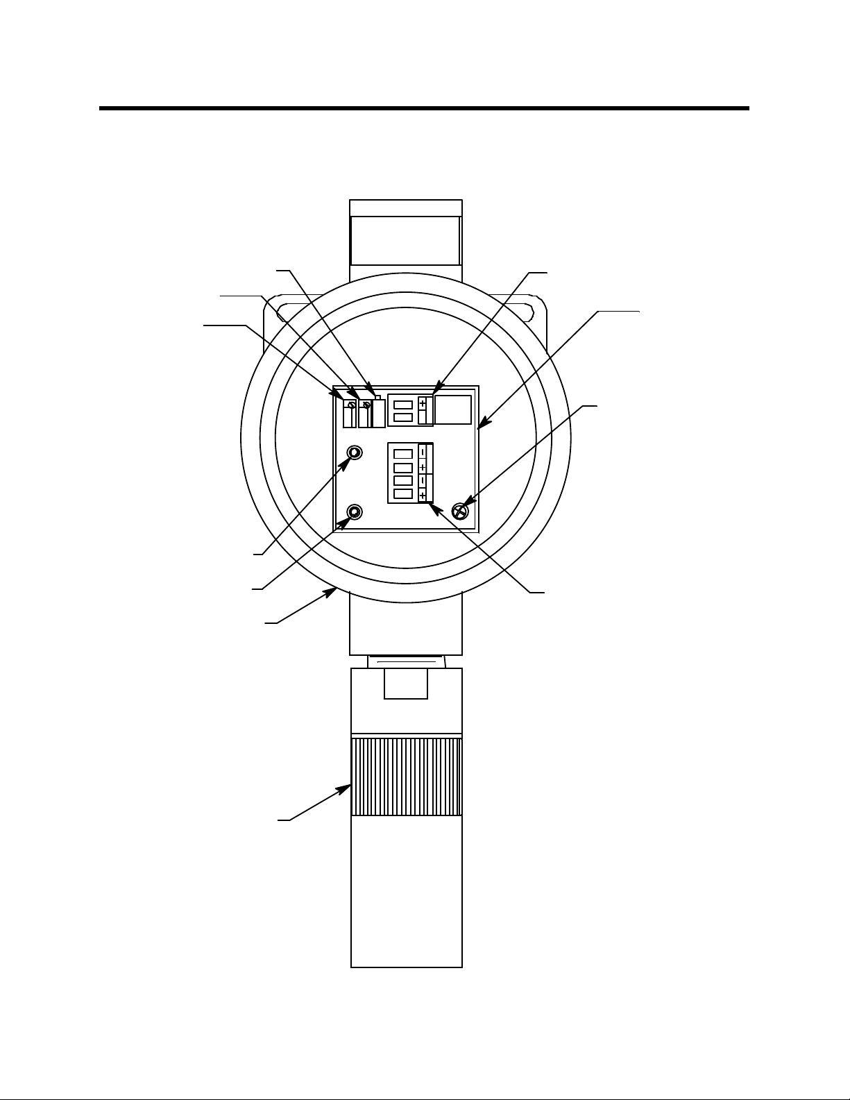
Description
This section describes the components of the toxic gas transmitter. The toxic gas
transmitter is a 4 - 20 mA type detector head. It consists of the toxic detector, amplifier,
and juncti on box.
Factory Adjust Pot
Span Pot
Zero Pot
Red +TestPoint
Black - Test Point
J-B ox
Controller TerminalS trip
Amplifier
ZERO
SPAN
S
SIG /P W R
TOXIC OXY
Mounting Screw
Detector Termi nalStrip
Toxic Detector
Figure 1: Toxic Transmitter Component Location
2 • 65-2340RKSS Toxic Gas Transmitter
Page 7
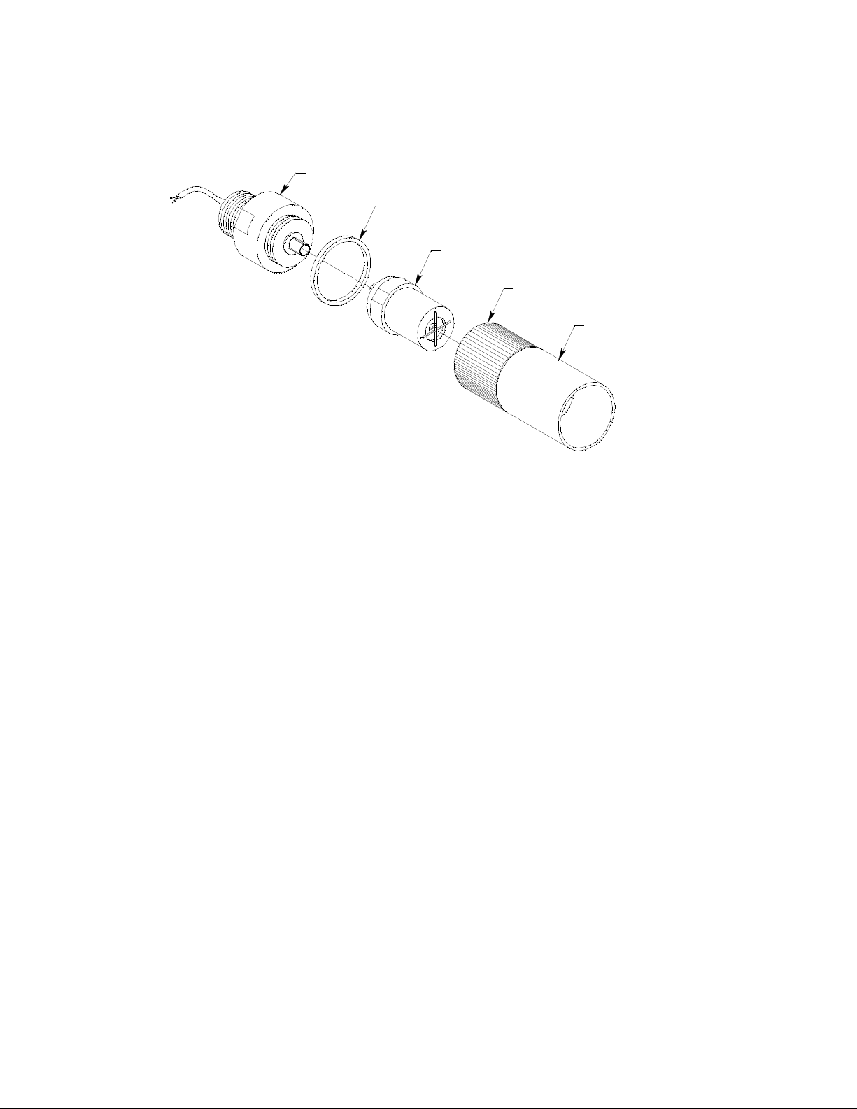
Toxic Detector
The toxic detector consists of the detector housing body, detector housing cap,
splashguard, cap gasket, and the plug -in sensor.
Det e c tor H o us ing Body
(different for each detector type)
Cap Gasket
Sensor
(different for each detector type)
Detect or Ho usin g
Cap
Splas h Guard
(removable)
Figure 2: Toxic Detector Component Location
Detector Housing Body
The detector housing body protects the electronic components within the housing. Use the
mounting threads at the top of the housing to screw the toxic detector into the 3/4” NPT
hub on the bottom of the junction box. Two wires extend from the top of the detector
housing body. Use these wires to connect the toxic detector to the amplifier. One of the
wires is black and one of the wires is color coded depending on the detector type. See
Figure 4 on page 7 for the color code assignments.
The housing body includes a 12 position connector at the bottom of the housing body. The
plug-in sensor mates to this connector. A pre-amplifier located between the connector and
the two interconnect wires conditions the sensor’s signal before the signal reaches the
controller . Ea ch plug-in sensor type (Cl
for example) requires a diffe rent pr e-amplifier, so
2
there is a different detector housing body for each gas type.
Housing Cap, Cap Gasket, & Splashguard
The housing cap screws onto the detector housing. It retains the plug-in sensor and
protects it from damage. A removable splashguard is screwed onto the detector cap to
protect the sensor from impact damage, direct water spray, and splashing. Unscrew the
detector cap to access the sensor for maintenance or replacement. A cap gasket seals the
interface between the housing and cap.
Plug-In Sensor
The plug-in sensor is secured in the detector assembly by the housing cap. There is a
different sensor for each target gas. Through a series of chemical and electrical reactions,
the sensor produces an electrical output that corresponds to the detection range of the
sensor.
Amplifier
The amplifier converts the electrical output from the detector to a 4 to 20 mA signal that
corresponds to the detection range and transmits the signal to a gas monitoring controller .
65-2340RKSS Toxic Gas Tr a nsm itter • 3
Page 8

A foam gasket that orients the amplifier and keeps it from rotating is installed on the
bottom of the amplifier. The amplifier includes the detector terminal strip, controller
terminal strip, zero pot, span pot, and test points (see Figure 1).
Controller Terminal Strip
The controller terminal strip is a two position plug-in style terminal s trip located at the
top edge of the amplifier. Use the controller terminal strip to wire the transmitter to a
controller.
Detector Terminal Strip
The detector terminal strip is a four position plug-in style terminal strip located below the
controller terminal strip. Two of the positions are for use with an oxygen sensor and are
not used in the toxic gas transmitter. Use the two detector terminal strip positions that are
labelled “TOXIC” to connect the detector to the amplifier.
NOTE: The detector is factory-wired to the detector terminal strip. See “Wiring the Toxic
Gas Transmitter to a Controller” on page 6 for all wiring procedures related to
the transmitter.
Zero Pot
The zero pot is located in the upper left corner of the amplifier (see Figure 1). Use a small
flat blade screwdriver to turn the zero pot’s adjustment screw and adjust th e amplifier’s
zero (fresh air) output during the start-up and calibration procedures. Turn the adjustment screw clockwise to increase the zero output and counterclockwise to decrease the
zero output.
Span Pot
The span pot is located to the right of the zero pot (see Figure 1). Use a small flat blade
screwdriver to turn the span pot’s adjustment screw and adjust the amplifier’s gas
response output during the calibration procedure. Turn the adjustment screw clockwise to
increase the span output and counterclockwise to decrease the span output.
CAUTION: The amplifier includes an additional potentiometer. It is factory-set. Do not adjust it.
Test Points
The test points are on the left side of the amplifier (see Figure 1). The test points produce a
100 mV to 500 mV output that corresponds to the transmitter’s 4 to 20 mA output. Use the
test points and a voltmeter to measure the amplifier’s output during the start-up and
calibration procedures. The black test point in the lower left corner is the negative (-) test
point and the red test point below the zero pot is the positive (+) test point.
Junction Box
The stainless steel, corrosion resistant junction box allows you to install the detector at a
mounting site that is remote from a controller, and it protects the detector wiring
connections. Two conduit hubs allow yo u to m oun t the detector to the junction box and
connect the wiring from the detector to a controller. An O-ring seals the interface between
the junction box cover and the junction box base.
A cover on the front of the junction box allows access to the interior of the junction box. A
locking set screw on the junction box cover allows you to secure the junction box cover
and prevent it from being removed.
4 • 65-2340RKSS Toxic Gas Transmitter
Page 9

Installation
This section describes procedures to mount the toxic gas transm itter in the monitoring
environment and wire the transmitter to a controller.
Mounting the Toxic Gas Transmitter
1. Select a mounting site that is representative of the monitoring environment. Consider
the following when you select the mounting site.
• Select a site where the transmitter is not likely to be bumped or disturbed. Make
sure there is sufficient room to perform start-up, maintenance, and calibration
procedures.
• Select a site where the target gas is likely to be found first.
3.66
3.15
2.40
3/4 NPT
Conduit Hub
Text O riented
This W a y
.20 Dia. x .45
Slot, 2X
10.00 Max
Junction
Box
Toxic
Detector
Figure 3: Mounting the Toxic Gas Transmitter
65-2340RKSS Toxic Gas Tr a nsm itter • 5
1.10
Page 10

2. At the monitoring site you select, hang or mount th e jun c tion box with the detector
facing down (see Figure 3).
Wiring the Toxic Gas Transmitter to a Controller
WARNING: Always verify that power to the controller is off before you make wiring
connections.
1. Turn off the controller.
2. Turn off power to the controller.
3. Remove the junction box cover.
4. The detector leads are factory wired. Verify that the detector leads are wired to the
amplifier’s detector terminal strip as shown in Figure 4.
5. To gain access to a plug-in terminal strip for wiring, pull it out o f its socket by
grasping the terminal strip and pulling. The detecto r strip is keyed so that the
controller and detector terminal strips cannot be reversed inadvertently.
6. Guide a two-conductor, shielded cable or two wires in conduit through the top
conduit hub of the junction box.
7. Pull out the controller terminal strip, and connect the two wires to the terminal strip
as follows (see Figure 4).
• Connect the positive wire to the SIG/PWR “+” terminal.
• Connect the signal wire to the SIG/PWR “S” terminal.
CAUTION: If shielded cable is used, leave the cable shield ’s drain wire disconnected and
insulated at the transmitter. You will connect the opposit e end of the cable’s drain
wire to the controller’s chassis (earth) ground.
8. Reinstall the controller terminal strip into its socket.
9. Secure the junction box cover to the junction box.
10. Route the cable or wires leading from the toxic gas transmitter through one of the
conduit hubs at the controller housing.
CAUTION: Do not route power and transmitter wiring through the same controller conduit hub.
The power cabl e may disrupt the transmission o f the transmitte r signal to the
controller.
11. Connect the wires to the applicable detector/transmitter terminal strip at the
controller as shown in Figure 4.
6 • 65-2340RKSS Toxic Gas Transmitter
Page 11

Controller Detector/Transmitter
+
Terminals, Typical Designations
S
Controller Housing
Cable Shi eld
J-Box
Gas Type Table
S
ZERO
SPAN
SIG/PWR
Gas Type + Wire
AsH3 brown
0-3ppmCl2
T OX IC OX Y
0- 10 ppmCl2
CL2 yellow
CL-10 yel low
HCN white
NH3 red
PH3 g reen
Black
SO2 blue
(+) S ee Ta ble
Toxi c Detector
Figure 4: Wiring the Toxic Gas Transmitter to a Controller
12. If shielded cable is used, connect the cable’s drain wire to an available chassis (earth)
ground at the controller. RKI controllers typically have a ground stud that can be used
to ground the cable’s drain wire.
65-2340RKSS Toxic Gas Tr a nsm itter • 7
Page 12

Start Up
This section describes procedures to start up the toxic gas transmitter and place the
transmitter into normal operation.
Introducing Incoming Power
1. Complete the installation procedures described earlier in this manual.
2. Ve rify that the power wiring to the controller is correct and secure. Refer to the
controller operator’s manual.
3. Turn on power to the controller.
4. Turn on the controller.
5. Verify that the controller is on and operating properly. R efer to the controller
operator’s ma nual.
CAUTION: Allow the transmitter to warm up for 5 minutes before you continue with the next
section, “Setting the Zero Signal”.
Setting the Zero Signal
CAUTION: If you suspect the presence of toxic g a s in the monitoring environment, use the
calibration kit and the zero air calibration cylinder to introduce “fresh air” to t he
detector and verify an accurate zero setti n g. Se e “Cal i b ration ” on pa ge 14 for
instructions to apply zero air when setting the zero signal.
1. Verify that the transmitter is in a fresh air environment (environment known to be free
of toxic gas).
2. Unscrew and remove the junction box cover from the junction box.
3. Set a voltmeter to measure in the millivolt (mV) range.
4. Plug the voltmeter leads into the test points on the amplifier. Plug the positive lead
into the red + test point; plug the negative lead into the black - test point.
5. Verify a voltmeter reading of 100 mV (±2 mV).
6. If necessary, use a small flat-blade screwdriver to adjust the zero pot until the
voltmeter reading is 100 mV (±2 mV).
7. Remove the voltmeter leads from the test points.
8. Secure the junction box cover to the junction box.
8 • 65-2340RKSS Toxic Gas Transmitter
Page 13

Maintenance
This section describes maintenance procedures. It includes preventive maintenance,
troubleshooting, and component replacement procedures.
Preventive Maintenance
This section describes a preventive maintenance schedule to ensure the optimum
performance of the toxic gas transmitter. It includes daily, monthly, and quarterly
procedures.
Daily
Verify a display reading of 0 ppm at the controller. Investiga te significant changes in the
display reading.
Monthly
This procedure describes a test to verify that the toxic gas transmitter responds properly
to the target gas. It describes the test using a calibration kit that includes a calibration cup,
calibration gas, sample tubing, and a fixed flow regulator with an on/off knob. See Table 3
on page 14 to determine the correct calibration cup and regulator for the required flowrate
for your detector.
WARNING: Failure to use the recommended calibration cup and calibration gas flow
rate will result in an inaccurate reading.
NOTE: Perfor ming a r esp onse te st on t he toxic gas trans mitter ma y cause al arms. Be sur e
to put the controller into its calibration mode or disable external alarms before
performing this test.
Preparing for the response test
1. Place the controller into its calibration mode or disable external alarms.
2. Verify that the controller display reading for the channel you are testing is 0 ppm.
If the display reading is not 0 ppm, set the zero reading of the transmitter as described
in “Start Up” on page 8, then continue this procedur e.
3. Unscrew and remove the junction box cover.
4. Set a voltmeter to read in the millivolt (mV) range.
5. Plug the voltmeter leads into the test points on the amplifier. Plug the positive lead
into the red + test point; plug the negative lead into the black - test point.
6. Use the following formula to determine the correct test points output for the test
sample.
Output (mV) = (test sample/fullscale) X 400 + 100
For example, with a test sample of 0.5 ppm and a fullscale setting of 1.00 ppm, the
correct output is 300 mV.
300 (mV) = (.50/1.00) X 400 +100
7. Unscrew the splashguard from the housing cap. Make su re the housing cap remains
screwed firmly onto the housing body.
8. Screw the regulator into the calibration cylinder.
65-2340RKSS Toxic Gas Tr a nsm itter • 9
Page 14

9. Use the sample tubing to connect the regulator to the calibration cup. Check the
bottom of the calibration cup to see if it has a specified flow direction through the cup
and if it does, make sure you connect the tube from the regulator to the inlet port. The
81-1138RK calibration cup, which is used for all detectors except for Cl2 and NH3
detectors, has a specified flow direction on the bottom of the cup. The 81-1138RK-CL2
and 81-1138RK-NH3 calibration cu ps do not have a specified flo w direction.
10. Push the calibration cup onto the plug-in sensor that sticks through the housing cap
as far as it will go. The cup seals to the sensor with an O-ring. Make sure to use the
correct calibration cup and sample flowrate for your detector.
Performing the response test
1. Turn the regulator’s on/off knob counterclockwise to open the regulator. Gas will
begin to flow
2. Allow the gas to flow for two minutes, then verify that the reading is within ± 20% of
the cylinder gas concentration.
NOTE: If the reading is not within ± 20% of the correct response reading, calibrate the
detector as described in “Calibration” on page 14.
3. Turn the regulator’s on/off knob clockwise to close the regulator.
4. Unscrew the regulator from the calibration cylind er.
5. Gently pull the calibration cup off of the plug-in sensor.
6. Screw the splashguard firmly back onto the housing cap.
7. Remove the voltmeter leads from the amplifier test points.
8. Reinstall the junction box cover.
9. When the controller display reading falls below th e alarm setpoints, return the
controller to normal operation.
10. Store the components of the calibration kit in a sa fe place.
Quarterly
Calibrate the toxic gas transmitter as described in “Calibration” on page 14 of this manual.
Troubleshooting
The troubleshooting guide describes symptoms, probable causes, and recommended
action for problems you may encounter with the toxic gas transmitter.
NOTE: This troubleshooting guide describes transmitter problems only. See the
controller operator’s manual for problems you may encounter with the
controller.
10 • 65-2340RKSS Toxic Gas Transmitter
Page 15

Table 2:Troubleshooting the Toxic Gas Transmitter
Condition Symptom(s) Probable Causes Recommended Action
Fail Condition • Controller indicates a
Slow or No
Response/
Difficult or
Unable to
Calibrate
fail condition.
• Transmitter responds
slowly or does not
respond to response
test.
• Unable to accurately
set the zero or
response reading
during calibration.
• Transmitter requires
frequent calibration.
Note: Under “normal”
circumstances, the
transmitter requires
calibration once every 3
months.
Some applications
may require a more
frequent calibration
schedule.
• The transmitter wiring
is disconnected or
misconnected.
• The plug-i n sensor is
not properly plugged
into the socket in the
detector housing body.
• The transmitter’s zero
reading is low enough
to cause a fail
condition.
• The transmitter is
malfunctioning.
• The calibration cylinder
is low, out-dated, or
defective.
• The incorrect
calibration cup or
regulator is being
used.
• The plug-i n sensor
face is blocked w ith dirt
or some other
particulate
contamination.
• The calibration gas is
not an appr opriate
concentration.
• The transmitter is
malfunctioning.
1. Verify that the transmitter wiring is
correct and secure.
2. Confirm that the plug-in sensor is
installed properl y.
3. Perform a zero (fresh air) a djustmen t.
A full calibration is recommended.
4. If the fail condition continues, replace
the plug-in sensor as described later
in this section.
5. If the fail condition continues, contact
RKI for further instruction.
1. Verify that the calibration cylinder
contains an adequate supply of a
fresh test sample.
2. Confirm that yo u are using t he correct
calibration cup and regulator for your
detector type. See T able3 on page 14
for a list of t he required calibration
cups and regulators.
3. Check the plug-in sensor face and
remove any p articulate cont a mination
if necessary.
4. Verify that the calibration gas
concentration is appropriate for the
transmitter. The concentration should
be in the detection range, preferably
about half of the detection range.
5. If the calibration/response difficulties
continue, replace the plug-in sensor
as described later in this section.
6. If the calibration/response difficulties
continue, contact RKI for further
instruction.
Replacing Components of the Toxic Gas Transmitter
This section includes a procedure to replace the plug-in toxic sensor, a procedure to
replace the entire toxic detector assembly, and one to replace the amplifier. In most cases,
it is not necessary to replace the entire detector assembly.
Replacing The Plug-in Toxic Sensor
CAUTION: The plug-in sensor contains electrolyte which is a dilute acid. Do not disassemble the
sensor when replacing it with a new one. If sensor electrolyte comes in contact with
your skin, wash affected area thoroughly with soap and water.
1. Turn off the controller.
2. Turn off or unplug p ower to the controller.
3. Unscrew the detector housing cap with the spla shguard from the detector housing
body. Mak e sure not to lose the cap gasket.
65-2340RKSS Toxic Gas Tr a nsm itter • 11
Page 16

4. Unplug and remo ve the toxic sens or.
5. Carefully plug the replacement sensor into the connector that is located in the detector
housing body.
WARNING: You must replace the plug-in sensor with the same type of sensor that is
installed. A detector cannot be converted from one type of detector to
another by using a different plug-in sensor. For example, if you are
replacing a Cl2 sensor, you must replace it with a Cl2 sensor.
6. Make sure the cap gasket is in place and screw the detector housing cap with the
splashguard back onto the detector housing body.
7. Turn on power to the controller.
8. Turn on the controller and place into normal operation.
CAUTION: Allow the replacement se nsor to wa rm up for 5 minutes before you continue with the
next step.
9. Calibrate the detector as described in “Calibration” on page 14.
Replacing the Toxic Detector
NOTE: In most cases, it is only necessa r y to replace th e p lug- in sensor.
1. Turn off the controller.
2. Turn off or unplug p ower to the controller.
3. Remove the junction box cover.
4. Remove the detector terminal strip from its socket.
5. Disconnect the detector leads from the detector terminal strip. Note the position of the
color-coded leads as you remove them.
6. Unscrew the detector from the junction box conduit hub.
7. Guide the detector leads of the replacement detector through the bottom conduit hub
of the junction box, then screw the mounting threads of the detector into the conduit
hub. If necessary for environmental conditions, apply thread sealant or teflon tape to
the hub and/or detector threads to seal them.
8. Connect the detector leads to the appropriate detector terminal strip terminals.
Connect the black wire to the terminal labelled TOXIC - and the color coded wire to
the terminal labelled TOXIC +. See Figure 4 on page 7 for the detector wiring
connections to the amplifier and the detector wire color coding.
9. Reinstall the junction box cover.
10. Turn on or plug in power to the controller.
11. Turn on the controller and place it into normal operation.
CAUTION: Allow the replacement detector to warm up for 5 minutes before y o u c o ntinue with
the next step.
12. Calibrate the replacement detector as described in “Calibration” on page 14.
12 • 65-2340RKSS Toxic Gas Transmitter
Page 17

Replacing the Amplifier
1. Turn off the controller.
2. Turn off or unplug p ower to the controller.
3. Remove the junction box cover.
4. Unplug the detector terminal strip and controller terminal strip from their sockets.
You may leave the wires connected to the terminal strips.
5. Unscrew and remove the screw with the flat and lock washers that secures the
amplifier to the junction box.
6. Remove the old amplifier.
7. Install the new amplifier in to the junction box with the screw, lock washer, an d flat
washer you removed in Step 5 above. A foam gasket that orients the amplifier and
keeps it from rotating is installed on the bottom of the amplifier. Make sure the
amplifier is seated flat in the junction box.
8. Install the detector and controller terminal strips into their socket s on the new
amplifier as shown in Figu re 4 on page 7. If controller leads or detector leads were
removed during this procedure, refer to Figure 4 on page 7 for the detector and
amplifier connections.
NOTE: When a transmitter is first powered up with a new amplifier, the initial output
may be either high or below zero depending on the setting of the zero pot. Be
sure to make arrangements so that this does not cause unwanted alarms.
9. Turn on power to the controller.
10. Turn on the controller and place it into normal operation.
11. Allow the transmitter to warm-up for 5 minutes.
12. Calibrate the transmitter as described in “Calibration” on page 14 of this manual.
Calibration Frequency
Although there is no particular calibration frequency that is correct for all applications, a
calibration frequency of every 3 months is adequate for most toxic gas transmitter
applications. Unless experience in a particular application dictates otherwise, RKI
Instruments, Inc. recommends a calibration frequency of every 3 months for the toxic gas
transmitter.
If an application is not very demanding, for example detection in a clean, temperature
controlled environment where toxic gas is not normally present, and calibration
adjustments are minimal at calibration, then a calibration frequency of every 6 months is
adequate.
If an application is very demanding, for example if the environment is not well controlled
or if toxic gas is often present, then more frequent calibration than every 3 months may be
necessary.
65-2340RKSS Toxic Gas Tr a nsm itter • 13
Page 18

Calibration
This section describes how to calibrate the toxic gas transmitter. It includes procedures to
prepare for calibration, set the zero (fresh air) reading, set the span (response) reading,
and return to normal operation. It describes calibration using a calibration kit that
includes a calibration cup, calibration gas, sample tubing, and a fixed flow regulator with
an on/off knob. The required sample flow rate and calibration cup depend on the
transmitter being calibrated. Table 3 below lists the required calibration cups and
regulators for the various toxic gas transmitters.
Table 3: Required Calibration Cups and Flow Rates
Required Regulator/
Flowrate for Calibration
Gas
Yes
Transmitter Type
Arsine (AsH
Required
Calibration Cup
) 81-1138RK 81-1051RK, 0.5 LPM (liters
3
per minute)
Chlorine (Cl
), 0 - 3.00 ppm
2
81-1138RK-CL2 81-1051RK, 0.5 LPM No
and 0 - 10.0 ppm
Hydrogen Cyanide (HCN) 81-1138RK-HCN 81-1051RK, 0.5 LPM Yes
Ammonia (NH
Phosphine (PH
Sulphur Di oxide (SO
) 81-1138RK-NH3 81-1051RK-25, 0.25 LPM No
3
) 81-1138RK 81-1051RK, 0.5 LPM Yes
3
) 81-1138RK 81-1051RK, 0.5 LPM Yes
2
W ARNING: Not using the recommended calibration cup, sample flowrate, and specified
flow direction (for 81-1138RK calibration cup only) will result in an
inaccurate calibration. Make sure to use the calibration cup and sample
flow rate listed in Table 3 for your target gas when performing a
calibration. Also make sure to connect the sample tubing to the calibration
cup port that results in the specified flow direction for the 81-1138RK
calibration cup.
Flow Direction
Specified on
Calibration Cup
Prepari ng for Ca libration
1. Place the controller into its calibration mode or disable external alarms.
2. Unscrew and remove the junction box cover.
3. Set a voltmeter to measure in the millivolt (mV) range.
4. Plug the voltmeter leads into the test points on the amplifier. Plug the positive lead
into the red + test point; plug the negative lead into the black - test point.
5. Use the following formula to determine the correct test points output for the
calibrating sample.
Output (mV) = (calibrating sample/fullscale) X 400 + 100
14 • 65-2340RKSS Toxic Gas Transmitter
Page 19

For example, with a calibrating sample of .50 ppm and a fullscale setting of
1.00, the correct output is 300 mV.
300(mV) = (.50/1.00) X 400 +100
NOTE: Calibrating the toxic gas transm itter may cause alarms. Be sure to put the
controller into its calibration program or disable external alarms before
continuing.
6. Unscrew the splashguard from the detector housing cap. Make sure the cap remains
securely screwed onto the housing body.
7. Push the calibration cup onto the plug-in sensor tha t sticks through the housing cap.
The calibration cup seals to the sensor with an O-ring.
Setting the Zero (Fresh Air) Reading
NOTE: If you can verify that the toxic gas transmitter is in a f resh air environment, you
do not need to apply zero air to the detector before adjusting the fresh air
reading.
1. Screw the regulator into the zero air calibration cylinder.
2. Use the sample tubing to connect the regulator to the calibration cup. Make su re to
connect the tube to the inlet side of the calibration cup if using the 81-1138RK
calibration cup which is marked on the outside bottom to show the required flow
dire ction t hrough the cup.
3. Turn the regulator knob counterclockwise to open the regulator.
4. Allow the gas to flow for two minutes and verify a reading of 100 mV (±2 mV). If
necessary, use the zero pot on the amplifier to adjust the reading to 100 mV (±2 mV).
5. Turn the regulator knob clockwise to close the regulator.
6. Unscrew the regulator from the zero air calibration cylinder. Leave the sample tubing
connected to the regulator and the calibration cup.
NOTE: Depending on the size of your zero air cylinder, it is possible that you will have a
different regulator for the zero air cylinder and toxic gas cylinder. If necessary to
fit the calibration toxic gas cylinder, change the regulator.
Setting the Span (Response) Reading
1. Screw the regulator into the calibration cylinder. Verify that the calibration gas is
representative of the transmitter’s target gas.
2. Turn the regulator knob counterclockwise to open the regulator.
3. Allow the calibration gas to flow for two minutes and verify that the reading matches
the response reading (±2 mV) you determined ea rlier. If necessary, use the span pot on
the amplifier to adjust the reading to match the correct response reading.
4. Turn the regulator knob clockwise to close the regulator.
5. Unscrew the regulator from the calibration cylinder and gently pull the calibration
cup off of the plug-in sensor.
65-2340RKSS Toxic Gas Tr a nsm itter • 15
Page 20

Returning to Normal Operation
1. Remove the voltmeter leads from the amplifier test points.
2. Gently pull the calibration cup off of the plug-in sensor
NOTE: For convenience, leave the regulator and calibration cup connected by the
sample tubing.
3. Screw the splashguard firmly back onto the housing cap.
4. Secure the junction box cover to the junction box.
5. When the controller display reading falls below th e alarm setpoints, return the
controller to normal operation.
NOTE: If you do not allow the gas reading to decrease below the alarm points, then
unwanted alarms may occur.
6. Verify that the controller display reading decreases and stabilizes a t 0 ppm.
7. Store the components of the calibration kit in a safe and convenient place.
Parts List
Part Number Description
06-1283RK Calibration kit sample tubing, 3 foot teflon w/flexible tubing on ends
07-0125RK Detector housing cap gasket
07-7151RK O-ring for junction box
10-5153RK Lid locking set screw for junction box
18-0416RK-11 Junction box with cover, stainless steel
57-1064RK-03 S2 series toxic amplifier
65-2300RK-ASH3 Replacement detector assembly, AsH
65-2300RK-CL2 Replacement detector assembly, Cl
65-2300RK-CL-10 Replacement detector assembly, Cl2 , 0 - 10.0 ppm range
65-2300RK-HCN Replacement detector assembly, HCN (includes plug-in sensor)
Table 4 lists replacement parts and accessories f or the toxic gas transmitter.
Table 4: Parts List
(includes plug-in sensor)
3
, 0 - 3.00 ppm range
(includes plug-in sensor)
(includes plug-in sensor)
2
65-2300RK -NH3 Replacement detector assembly, NH3 (includes plug-in sensor)
65-2300RK-PH3 Replacement detector assembly, PH
65-2300RK-SO2 Replacement detector assembly, SO
16 • 65-2340RKSS Toxic Gas Transmitter
(includes plug-in sensor)
3
(includes plug-in sensor)
2
Page 21

Table 4: Parts List
Part Number Description
71-0302RK 65-2340RKSS Operator’s Manual (this document)
81-0076RK Zero air calibration cylinder, 17 liter steel
81-0076RK-01 Zero air calibration cylinder, 34 liter steel
81-0076RK-03 Zero air calibration cylinder, 103 liter steel
81-0170RK-02 Calibration cylinder, 5 ppm SO
81-0170RK-04 Calibration cylinder, 5 ppm SO
81-0175RK-02 Calibration cylinder, 10 ppm NH
81-0175RK-04 Calibration cylinder, 10 ppm NH
in nitrogen, 58 liter aluminum
2
in nitrogen, 34 liter aluminum
2
in nitrogen, 58 liter aluminum
3
in nitrogen, 34 liter aluminum
3
81-0185RK-02 Calibration cylinde r, 0.5 ppm PH3 in nitrogen, 58 liter aluminum, used to calibrate
PH
and AsH3 detectors, see conversion factor on AsH3 plug-in sensors
3
81-0185RK-04 Calibration cylinde r, 0.5 ppm PH3 in nitrogen, 34 liter aluminum, used to calibrate
PH
and AsH3 detectors, see conversion factor on AsH3 plug-in sensors
3
81-0190RK-02 Calibration cylinder, 5 ppm Cl
81-0190RK-04 Calibration cylinder, 5 ppm Cl
81-0192RK-02 Calibration cylinder, 2 ppm Cl
81-0192RK-04 Calibration cylinder, 2 ppm Cl
in nitrogen, 58 liter
2
in nitrogen, 34 liter
2
in nitrogen, 58 liter, aluminum
2
in nitrogen, 34 liter aluminum
2
81-0196RK-02 Calibration cylinder, 10 ppm HCN in nitrogen, 58 liter aluminum
81-0196RK-04 Calibration cylinder, 10 ppm HCN in nitrogen, 34 liter aluminum
81-1050RK Regulator with gauge and knob, 0.5 LPM, for 17 liter and 34 liter steel calibration
cylinders (used for 34 liter zero air cylinder only)
81-1051RK Regulator with gauge and knob, 0.5 LPM, for 34AL/58/103 liter calibration
cylinders
81-1051RK-25 Regulator with gauge and knob, 0.25 LPM, for 34AL/58/103 liter calibration
cylinders (used to calibrate NH
81-1138RK Calibration cup, general (SO
toxic detector only)
3
), for ESM-01, use 0.5 LPM flow
2
81-1138RK-CL2 Calibration cup, for ESM-01 Cl2, use 0.5 LPM flow
81-1138RK-NH3 Calibration cup, for ESM-01 NH3, use 0.25 LPM flow
81-F503RK Calibration kit, includes regulator, calibration cup, and a 58 liter 10 ppm NH
nitrogen aluminum calibration cylinder
81-F503RK-LV Calibration kit, includes regulator, calibration cup, and a 34 liter 10 ppm NH
nitrogen aluminum calibration cylinder
81-F603RK Calibration kit, includes regulator, calibration cup, and 58 liter 2 ppm CL2 in
nitrogen aluminum calibration cylinder
65-2340RKSS Toxic Gas Tr a nsm itter • 17
3
3
in
in
Page 22

Table 4: Parts List
Part Number Description
81-F603RK-LV Calibration kit, includes regulator, calibration cup, and 34 liter 2 ppm CL
2
in
nitrogen aluminum calibration cylinder
81-F702RK Calibration kit, includes regulator, calibration cup, and a 58 liter 5 ppm SO
2
in
nitrogen aluminum calibration cylinder
81-F702RK-LV Calibration kit, includes regulator, calibration cup, and a 34 liter 5 ppm SO2 in
nitrogen aluminum calibration cylinder
81-F811RK Calibration kit, includes regulator, calibration cup, and a 58 liter 0.5 ppm PH
3
in
nitrogen aluminum calibration cylinder
81-F811RK-LV Calibration kit, includes regulator, calibration cup, and a 34 liter 0.5 ppm PH3 in
nitrogen aluminum calibration cylinder
ESM-01DH-ASH3 ESM-01 plug-in sensor, 0 - 1.50 ppm arsine
ESM-01DH-D-HCN ESM-01 plug-in sensor, 0 - 15.0 ppm hydrogen cyanide
ESM-01DH-D-SO2 ESM-01 plug-in sensor, 0 - 6.00 ppm sulphur dioxide, diffusion type only
ESM-01DH-PH3 ESM-01 plug-in sensor, 0 - 1.00 ppm phosphine
ESM-01R-D-NH3 ESM-01 plug-in sensor, 0 - 75.0 ppm ammonia, diffusion type only
ESM-K01-D-CL2 ESM-01 plug-in sensor, 0 - 3.00 ppm chlorine, diffusion type only
ESM-K01D-CL2-10 ESM-01 plug-in sensor, 0 - 10.0 ppm chlorine, diffusion type only
18 • 65-2340RKSS Toxic Gas Transmitter
 Loading...