

Page 1

65-2335RK
Carbon Monoxide Transmitter
Part Number: 71-0177RK
Revision: 0
Released: 4/12/11
Operator’s Manual
RKI Instruments, Inc.
www.rkiinstruments.com
Page 2

WARNING
Read and understand this instruction manual before operating
transmitter . Improper use of the transmitter could result in bodily
harm or death.
Periodic calibration and maintenance of the transmitter is essential for proper operation and correct readings. Please calibrate
and maintain this transmitter regularly! Frequency of calibration
depends upon the type of use you have and the sensor types.
T ypical calibration frequencies for most applications a re between
3 and 6 months, but can be required more often or less often
based on your usage.
65-2335RK CO Transmitter
Page 3

Product Warranty
RKI Instruments, Inc. warrants gas alarm equipment sold by us to be free from defects in
materials, workmanship, and performance for a period of one year fr o m date of shipment
from RKI Instruments, Inc. Any parts found defective withi n tha t period will be repaired
or replaced, at our option, free of charge. This warranty does not apply to those items
which by their nature are subject to deterioration or consumption in normal ser v ice, and
which must be cleaned, repaired, or replaced on a routine basis. Examples of such items
are:
W arranty is voided by abuse including mechanical damage, alteration, rough handling, or
repair procedures not in accordance with the operator’s manual. This warranty indicates
the full extent of our liability , a nd we are not r esponsible for removal or r eplacement costs,
local repair costs, transportation costs, or contingent expenses incurred without our prior
approval.
a) Absorbent cartridges d) Batteries
b) Pump diaphragms and valves e) Filter elements
c) Fuses
THIS WARRANTY IS EXPRESSLY IN LIEU OF ANY AND ALL OTHER
WARRANTIES AND REPRESENTATIONS, EXPRESSED OR IMPLIED,
AND ALL OTHER OBLIGATIONS OR LIABILITIES ON THE PART OF
RKI INSTRUMENTS, INC. INCLUDING BUT NOT LIMITED TO, THE
WARRANTY OF MERCHANTABILITY OR FITNESS FOR A
PARTICULAR PURPOSE. IN NO EVENT SHALL RKI INSTRUMENTS,
INC. BE LIABLE FOR INDIRECT, INCIDENTAL, OR CONSEQUENTIAL
LOSS OR DAMAGE OF ANY KIND CONNECTED WITH THE USE OF
ITS PRODUCTS OR FAILURE OF ITS PRODUCTS TO FUNCTION OR
OPERATE PROPERLY.
This warranty covers instruments and parts sold to users by authorized distributors,
dealers, and representatives as appointed by RKI Instruments, Inc.
We do not assum e i ndemnification fo r a ny accident or dama g e ca u s e d by the operation of
this gas monitor, and our warranty is limited to the replacement of parts or our complete
goods.
65-2335RK CO Transmitter
Page 4

Table of Contents
Overview . . . . . . . . . . . . . . . . . . . . . . . . . . . . . . . . . . . . . . . . . . . . . . . . . . . . . . . . . . . . . . . . . . . 1
Specifications. . . . . . . . . . . . . . . . . . . . . . . . . . . . . . . . . . . . . . . . . . . . . . . . . . . . . . . . . . . . . . . . 1
Description. . . . . . . . . . . . . . . . . . . . . . . . . . . . . . . . . . . . . . . . . . . . . . . . . . . . . . . . . . . . . . . . . . 2
CO Detector. . . . . . . . . . . . . . . . . . . . . . . . . . . . . . . . . . . . . . . . . . . . . . . . . . . . . . . . . . . . . . . . . . . . . . . . . . 3
Amplifier . . . . . . . . . . . . . . . . . . . . . . . . . . . . . . . . . . . . . . . . . . . . . . . . . . . . . . . . . . . . . . . . . . . . . . . . . . . . 4
Junction Box. . . . . . . . . . . . . . . . . . . . . . . . . . . . . . . . . . . . . . . . . . . . . . . . . . . . . . . . . . . . . . . . . . . . . . . . . . 5
Installation . . . . . . . . . . . . . . . . . . . . . . . . . . . . . . . . . . . . . . . . . . . . . . . . . . . . . . . . . . . . . . . . . . 5
Mounting the CO Transmitter. . . . . . . . . . . . . . . . . . . . . . . . . . . . . . . . . . . . . . . . . . . . . . . . . . . . . . . . . . . 5
Wiring the CO Transmitter to a Controller . . . . . . . . . . . . . . . . . . . . . . . . . . . . . . . . . . . . . . . . . . . . . . . . 6
Startup. . . . . . . . . . . . . . . . . . . . . . . . . . . . . . . . . . . . . . . . . . . . . . . . . . . . . . . . . . . . . . . . . . . . . . 7
Introducing Incoming Power . . . . . . . . . . . . . . . . . . . . . . . . . . . . . . . . . . . . . . . . . . . . . . . . . . . . . . . . . . . 7
Setting the Zero Signal. . . . . . . . . . . . . . . . . . . . . . . . . . . . . . . . . . . . . . . . . . . . . . . . . . . . . . . . . . . . . . . . . 8
Maintenance. . . . . . . . . . . . . . . . . . . . . . . . . . . . . . . . . . . . . . . . . . . . . . . . . . . . . . . . . . . . . . . . . 9
Preventive Maintenance . . . . . . . . . . . . . . . . . . . . . . . . . . . . . . . . . . . . . . . . . . . . . . . . . . . . . . . . . . . . . . . 9
Troubleshooting . . . . . . . . . . . . . . . . . . . . . . . . . . . . . . . . . . . . . . . . . . . . . . . . . . . . . . . . . . . . . . . . . . . . . 10
Replacing Components of the CO Transmitter . . . . . . . . . . . . . . . . . . . . . . . . . . . . . . . . . . . . . . . . . . . 11
Calibration Frequency . . . . . . . . . . . . . . . . . . . . . . . . . . . . . . . . . . . . . . . . . . . . . . . . . . . . . . . 13
Calibration . . . . . . . . . . . . . . . . . . . . . . . . . . . . . . . . . . . . . . . . . . . . . . . . . . . . . . . . . . . . . . . . . 14
Preparing for Calibration. . . . . . . . . . . . . . . . . . . . . . . . . . . . . . . . . . . . . . . . . . . . . . . . . . . . . . . . . . . . . . 14
Setting the Zero Reading. . . . . . . . . . . . . . . . . . . . . . . . . . . . . . . . . . . . . . . . . . . . . . . . . . . . . . . . . . . . . . 14
Setting the Response Reading. . . . . . . . . . . . . . . . . . . . . . . . . . . . . . . . . . . . . . . . . . . . . . . . . . . . . . . . . . 14
Returning to Normal Operation. . . . . . . . . . . . . . . . . . . . . . . . . . . . . . . . . . . . . . . . . . . . . . . . . . . . . . . . 15
Parts List . . . . . . . . . . . . . . . . . . . . . . . . . . . . . . . . . . . . . . . . . . . . . . . . . . . . . . . . . . . . . . . . . . . 15
65-2335RK CO Transmitter
Page 5

Overview
This instruction manual describes the 65-2335RK carbon monoxide (CO) transmitter. This
manual also describes how to install, star t up, configure, maintain, and calibrate the
transmitter when using it with a gas monito ring controller. A parts list at the end of this
manual lists replacement parts and accessories for the CO transmitter. See the controller
operator’s manual for information specific to the controller.
Specifications
Table 1 lists specifications for the CO transmitter.
Table 1: Specifications
Target Gas Carbon Monoxide
Sampling Method Diffusion
Detection Range 0 to 25%
Accuracy ± 5% of reading or ± 5 ppm CO (whichever is greater)
Signal Output 4 to 20 mA
Response Time 90% in 30 seconds
W ARNING: When using the 65-2335RK, you must follow the instructions and warnings
in this manual to assure proper and safe operation of the 65-2335RK and to
minimize the risk of personal injury. Be sure to maintain and period ically
calibrate the 65-2335RK as described in this manual.
65-2335RK CO Transmitter • 1
Page 6
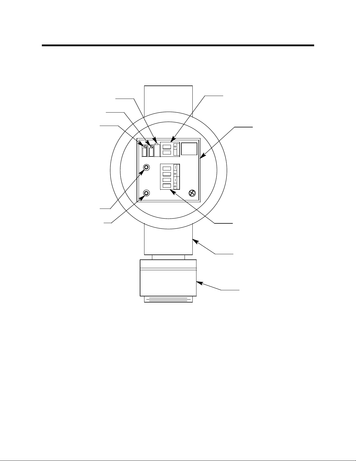
Description
This section describes the components of the CO transmitter. The CO transmitter is a 4 - 20
mA type detector head. It consists of the CO detector, amplifier, and junction box.
Factory Adjust Pot
Span Pot
Ze ro Pot
Test Point (Red)
est Point (Black)
ControllerTerminal St rip
Amplifier
SPAN
ZERO
S
SIG/PWR
TOXIC OXY
Detector Terminal Strip
J-Box
2 • 65-2335RK CO Transmitter
CO Detector
Figure 1: CO Transmitter Component Location
Page 7

CO Detector
c
The CO detector includes the detector housing body, detector housing, cap, cap gasket,
plug-in sensor, and charcoal filter.
Detector HousingBody
Cap Gasket
CO Plug-in Sensor
Charcoal Filter
w/Rubber Boot
Detector
Housing Cap
Hydrophobi
Membrane
Figure 2: Oxygen Detector Component Location
Detector Housing Body
The detector housing body protects the electronic components within the housing. Use the
mounting threads at the top of the detector housing to screw the CO detector into a 3/4”
NPT hub on the bottom of the junction box. Two wires extend from the top of the detector
housing body. Use these wires to connect the CO detector to the amplifier. One of the
wires is black and one of the wires is red.
The housing body includes a four-socket pattern at the bottom of the housing body. This
socket pattern accepts the sensor’s four pins to secure the sensor within the detector
housing. A pre-amplifier, located between the sockets and the two interconnect wires,
conditions the sensor’s signal before the signal reaches the controller.
Housing Cap & Cap Gasket
The housing cap screws onto the detector housing. It retains the sensor and the rubber
boot with the charcoal filter and protects them from damage. A hydrophobic membrane
on the outside of the cap face keeps water and particulates away from the charcoal filter
and sensor face behind the cap. Unscrew the detector cap to access the charcoal filter and
sensor for maintenance or replacement. A cap gasket seals the interface between the
housing and cap.
Plug-In CO Sensor
The plug-in sensor is secured in the dete ctor assembly by the housing cap. Through a
series of chemical and electrical reactions, the sensor produces an electrical output that
corresponds to the detection range of the detector.
65-2335RK CO Transmitter • 3
Page 8

Charcoal Filter
The disc-shaped charcoal filter is secured to the face of the CO sensor with a rubber boot.
The charcoal filter prevents interference gas e s ( hydrogen sulfid e [H
S] and certain hydro-
2
carbons) from producing false CO readings.
Amplifier
The amplifier converts the electrical output from the detector to a 4 to 20 mA signal that
corresponds to the detection range and transmits the signal to a gas monitoring controller .
A foam gasket that orients the amplifier and keeps it from rotating is installed on the
bottom of the amplifier. The amplifier includes the controller terminal strip, detector
terminal strip, zero pot, span pot, and test points (see Figure 1).
Controller Terminal Strip
The controller terminal strip is a two position plug-in style terminal s trip located at the
top edge of the amplifier. Use the controller terminal strip to wire the amplifier to a
controller.
Detector Terminal Strip
The detector terminal strip is a four position plug-in style terminal strip located below the
controller terminal strip. Two of the positions are for use with an oxygen detector and are
not used in the CO transmitter. Use the two detector terminal strip positions that are
labeled “TOXIC” to connect the detector to the amplifier.
NOTE: The detector is factory-wired to the detector terminal strip. See “Wiring the CO
Transmitter to a Controller” on page 6 for all wiring procedures related to the
transmitter.
Zero Pot
The zero pot is located in the upper left corner of the amplifier (see Figure 1). Use a small
flat blade screwdriver to turn the zero pot’s adjustment screw and adjust th e amplifier’s
zero (CO free) output during the start-up and calibration procedure. Turn the adjustment
screw clockwise to increase the zero output and counterclockwise to decrease the zero
output.
Span Pot
The span pot is located to the right of the zero pot (see Figure 1). Use a small flat blade
screwdriver to turn the span pot’s adjustment screw an d adjust the amplifier’s response
output during the start-up and calibration procedure. Turn the adjustment screw
clockwise to increase the response output and counterclockwise to decrease the response
output.
CAUTION: The amplifier includes an additional pot. It is factory-set. Do not adjust it .
Test points
The test points are on the left side of the amplifier (see Figure 1). The test points produce a
100 mV to 500 mV output that corresponds to the transmitter’s 4 to 20 mA output. Use the
test points and a voltmeter to measure the amplifier’s output during the star t-up and
calibration procedures. The black test point in the lower left corner is the negative (-) test
point and the red test point below the zero pot is the positive (+) test point.
4 • 65-2335RK CO Transmitter
Page 9

Installation
Junction Box
Use the junction box to install the transmitter at a mounting site that is remote from the
controller. The junction box protects the amplifier and wiring connections made to the
amplifier. Use the top 3/ 4’’ conduit hub to connect wiring from the amplifier to the
controller. Use the cover on the front of the junction box to access the in terior of the
junction box. The detector and amplifier are factory installed in the junction box. Three
spacers installed on the back of the junction box control the distance of the junction box
from a mounting surface and ensure that there is enough room to install a calibration cup
on the detector during calibration.
This section describes procedures to mount the CO transmitter in the monitoring
environment and wire the transmitter to a controller.
Mounting the CO Transmitter
1. Select a mounting site that is representative of the monitoring environment. Consider
the following when you select the mounting site.
• Select a site where the transmitter is not likely to be bumped or disturbed. Make
sure there is sufficient room to perform start-up, maintenance, and calibration
procedures.
• Select a site that is at normal breathing level.
3/4 NPT
Female
3.65
6.8 Max
J-Box
3.10
.75
.38
Rubber
Spacers
3X
CO Detector
1 1/2- 20 Thr e ad fo r Cali b rat i on Cup
Figure 3: Mounting the CO Transmitter
65-2335RK CO Transmitter • 5
Page 10

2. At the monitoring site you select, hang or mount th e jun c tion box with the detector
facing down (see Figure 3).
Wiring the CO Transmitter to a Controller
WARNING : Always verify that power to the controller is off before you make wiring
connections.
1. Turn off the controller.
2. Turn off power to the controller.
3. Remove the junction box cover.
4. The detector leads are factory wired. Verify that the detector leads are wired to the
amplifier’s detector terminal strip as shown in Figure 4.
5. To gain access to a plug-in terminal strip for wiring, pull it out of its socket by
grasping the terminal strip and pulling. The detector terminal strip is keyed so that
the controller and detector terminal strips cannot be reversed inadvertently.
6. Guide either a two-conductor, shielded cable, or two wires in conduit through the top
conduit hub of the junction box.
7. Pull out the controller terminal strip, and connect the two wires to the terminal strip
as follows (see Figure 4).
• Connect the positive wire to the SIG/PWR “+” terminal.
• Connect the signal wire to the SIG/PWR “S” terminal.
CAUTION: If shielded cable is used, leave the cable shield ’s drain wire disconnected and
insulated at the transmitter. You will connect the opposite end of the cable’s drain
wire to the controller’s chassis (earth) ground.
8. Reinstall the controller terminal strip into its socket.
9. Secure the junction box cover to the junction box.
10. Route the cable or wires leading from the CO transmitter through one of the conduit
hubs at the controller housing.
CAUTION: Do not route power and transmitter wiring through the same controller conduit hub.
The power cabl e may disrupt the transmission o f the transmitte r signal to the
controller.
11. Connect the wires to the applicable detector/transmitter terminal strip at the
controller as shown in Figure 4.
6 • 65-2335RK CO Transmitter
Page 11

Controller Detector/Transmitter
Terminals, Typical Designations
Controller Housing
S
+
J-Box
CO Dete ctor
Cabl e Shi eld
S
SPAN
ZERO
SIG/PWR
TOXIC OXY
Black
Red
Start Up
Figure 4: Wiring the CO Transmitter to a Controller
12. If shielded cable is used, connect the cable’s drain wire to an available chassis (earth)
ground at the controller. RKI controllers typically have a ground stud that can be used
to ground the cable’s drain wire.
This section describes procedures to start up the CO transmitter and place the transmitter
into normal operation.
Introducing Incoming Power
1. Complete the installation procedures described earlier in this manual.
2. Verify that the power wiring to the controller is correct and secure. Refer to the
controller operator’s manual.
3. Turn on power to the controller.
4. Turn on the controller.
5. Verify that the controller is on and operating properly. Refer to the controller
operator’s ma nual.
65-2335RK CO Transmitter • 7
Page 12

CAUTION: Allow the transmitter to warm up for 5 minutes before you continue with the next
section, “Setting the Zero Signal”.
Setting the Zero Signal
CAUTION: If you suspect the presence of the target gas in the monitoring environment, use the
calibration kit and the zero air calibration cylinder to introduce “fresh air” to t he
sensor and verify an accurate zero setting.
NOTE: If you can verify that the detector is in a fresh air environment (environment
known to be of normal oxygen content and free of toxic and combustible gases),
it is not necessary to apply zero air when verifying or setting the fresh air
reading.
The procedure below describes applying zero emission air, usually called zero air , using a
calibration kit that includes a calibration cup, calibration gas, sample tubing, and a fixed
flow regulator with an on/off knob. RKI Instruments, Inc. recommends using a 0.5 LPM
(liters per minute) fixed flow regulator.
1. Unscrew and remove the junction box cover from the junction box.
2. Set a voltmeter to measure in the millivolt (mV) range.
3. Plug the voltmeter leads into the test points on the amplifier. Plug the positive lead
into the red (+) test point; plug the negative lead into the black (-) test point.
4. Screw the calibration cup onto the bottom of the CO detector.
5. Screw the regulator into the zero air calibration cylinder.
6. Use the sample tubing to connect the regulator to the calibration cup.
7. Turn the regulator’s on/off knob counterclockwise to open it. Gas will begin to f low.
8. Allow the gas to flow for two minutes.
9. Verify a voltmeter reading of 100 mV (±2 mV).
10. If necessary, use a small flat-blade screwdriver to adjust the zero pot until the
voltmeter reading is 100 mV (±2 mV).
11. Turn the regulator’s on /off knob clockwise to close it.
12. Unscrew the calibration cup from the detector.
13. Unscrew the regulator from the zero air calibration cylinder. For convenience, leave
the sample tubing connected to the regulator and the calibration cup.
14. Store the components of the calibration kit in a safe and conve nient place.
15. Remove the voltmeter leads from the test points.
16. Secure the junction box cover to the junction box.
8 • 65-2335RK CO Transmitter
Page 13

Maintenance
This section describes maintenance procedures. It includes preventive maintenance,
troubleshooting, and component replacement procedures.
Preventive Maintenance
This section describes a preventive maintenance schedule to ensure the optimum
performance of the CO transmitter. It includes daily, monthly, and quarterly procedures.
Daily
Verify a display reading of 0 PPM CO at th e co ntroller. Investigate significant changes in
the display reading.
Monthly
This procedure describes a test to verify that the CO transmitter responds properly to
carbon monoxide. It describes the test using a calibration kit that includes a ca libration
cup, calibration gas, sample tubing, and a fixed flow regulator with an on/off knob.
NOTE: Performing a response test on the CO transmitter may cause alarms. Be sure to
put the controller into its calibration mode or disable external alarms before
performing this test.
Preparing for the response test
1. Place the controller into its calibration program or disable external alarms.
2. Verify that the controller display reading for the channel you are testing is 0.
If the display reading is not zero, set the zero reading of the transmitter as described
in the Start Up section of this manual, then continue this procedure.
3. Unscrew and remove the junction box cover.
4. Set a voltmeter to measure in the millivolt (mV) range.
5. Plug the voltmeter leads into the test points on the amplifier. Plug the positive lead
into the red (+) test point; plug the negative lead into the black (-).
6. Use the following formula to determine the correct test points output for the test
sample.
Output (mV) = (calibrating sample/fullscale) X 400 + 100
For example, with a test sample of 50 PPM CO and a fullscale setting of
300 PPM, the correct output is 167 mV.
167 (mV) = (50/300) X 400 +100
7. Screw the regulator into the calibration cylinder.
8. Use the sample tubing to connect the regulator to the calibration cup.
Performing the response test
1. Turn the regulator’s on/off knob counterclockwise to open the regulator. Gas will
begin to flow.
2. Allow the gas to flow for two minutes, then verify that the reading is within ± 10% of
the response reading you determined earlier.
65-2335RK CO Transmitter • 9
Page 14

NOTE: If the readings are not within ± 10% of the correct response reading, calibrate the
affected transmitter(s) as described in “Calibration” on page 14.
3. Turn the regulator’s on/off knob clockwise to close the regulator.
4. Unscrew the regulator from the calibration cylind er.
5. Unscrew the calibration cup from the CO detector.
6. Remove the voltmeter leads from the amplifier test points.
7. Reinstall the junction box cover.
8. When the controller display reading falls below th e alarm setpoints, return the
controller to normal operation.
9. Store the components of the calibration kit in a safe place.
Quarterly
Calibrate the CO transmitter as described in “Calibration” on page14 of this manual. See
the calibration frequency discussion in “Calibration Frequency” on page 13 to determine
if a quarterly calibration schedule fits your needs.
Troubleshooting
The troubleshooting guide describes symptoms, probable causes, and recommended
action for problems you may encounter with the CO transmitter.
NOTE: This troubleshooting guide describes transmitter problems only. See the
controller operator’s manual for problems you may encounter with the
controller.
Table 2:Troubleshooting the CO Transmitter
Condition Symptom(s) Probable Causes Recommended Action
Fail Condition Controller indicates a
fail condition.
• The transmitter wiring
to the controller is
disconnected or
misconnected.
• The wiring from the
detector to the
amplifier is
disconnected or
misconnected.
• The plug-in sensor is
not properly plugged
into the four-socket
pattern in the detector
housing body.
• The transmitter’s zero
reading is low enough
to cause a fail
condition.
• The transmitter is
malfunctioning.
1. V erify that the transmitter wiri ng to the
controller is correct and secure.
2. V erify that th e wiring from the detector
to the amplifier is correct and secure.
3. Confirm that the plug-in sensor is
properly installed.
4. Perform a zero adjustment. A full
calibration is recommended.
5. If the fail condition continues, replace
the sensor as described later in this
section.
6. If the fail condition continues, contact
RKI for further instruction.
10 • 65-2335RK CO Transmitter
Page 15

Table 2:Troubleshooting the CO Transmitter (cont.)
Condition Symptom(s) Probable Causes Recommended Action
Slow or No
Response/
Difficult or
Unable to
Calibrate
Unexplained
Upscale
Readings or
Alarms
• Transmitter responds
slowly or does not
respond to response
test.
• Unable to accurately
set the zero or
response reading
during calibration.
• Transmitter requires
frequent calibration.
Note: Under “normal”
circumstances, the
transmitter requires
calibration once every 3
months.
Some applications
may require a more
frequent calibration
schedule.
• Controller indicates a
CO reading that
cannot be verified.
• CO alarms occur at
the controller that
cannot be explained.
• The calibration cylinder
is low, out-dated, or
defective.
• The calibration gas is
not an appr opriate
concentration.
• The membrane on the
detector housing cap is
blocked with dirt or
some other particulate
matter.
• The transmitter is
malfunctioning.
• Charcoal filter is
saturated and no
longer scrubbing out
interfering gases.
1. Verify that the calibration cylinder
contains an adequate supply of a
fresh test sample.
2. Check the face of the detector
housing cap and remove any
particulate contamination from the
hydrophobic membrane if necessary.
3. Verify that the calibration gas
concentration is appropriate for the
transmitter. Zero emission air (20.9%
oxygen) is normally used for a zero
adjustment if the environment is
suspect and 50 PPM CO in air is
normally used for a response
adjustment.
4. If the calibration/response difficulties
continue, replace the sensor as
described later in this section.
5. If the calibration/response difficulties
continue, contact RKI for further
instruction.
1. Replace char co al filter.
2. If difficulties continue, contact RKI for
further instruction.
Replacing Components of the CO Transmitter
This section includes a procedure to replace the CO plug-in sensor, charcoal filter, and
amplifier. A procedure to replace the entire detector assembly is at the end of this section.
In most cases, it is not necessary to replace the entire detector assembly.
Replacing the Plug-In CO Sensor
CAUTION: The sensor contains electrol yte which is a dilute ac id. Do not disassemble the sensor
when replacing it with a new one. If sensor electrolyte comes in co ntact with your
skin, wash affected area thoroughly with soap and water.
1. Turn off the controller.
2. Turn off or unplug power to the co ntroller.
3. Unscrew the detector housing cap from the detection housing body. Make sure not to
lose the cap gasket.
4. Unplug and remove the CO plug -in sensor with the boot and charcoal filter attached.
5. Remove the rubber boot and charcoal filter from old sensor.
6. Install the rubber boot with charcoal filter onto the replacement sensor’s face.
7. Carefully plug the replacement sensor into the four-socket pattern that is located in
the detector housing.
8. Make sure the cap gasket is in place and screw the detector housing cap back onto the
detector housing body.
65-2335RK CO Transmitter • 11
Page 16

9. Turn on or plug in power to the controller.
10. Turn on the controller and place it into normal operation.
CAUTION: Allow the r ep la cem ent sens or to w arm up for 5 m inu tes before you continue with the
next step.
11. Calibrate the transmitter as described in “Calibration” on page 14.
Replacing the Charcoal Filter
1. Turn off the controller.
2. Turn off or unplug power to the co ntroller.
3. Unscrew the detector housing cap from the detector housing body.
4. Unplug and remove the CO plug -in sensor with the boot and charcoal filter attached.
5. Remove the rubber boot that secures the charcoal filter to the CO plug-in sensor.
6. Remove the charcoal filter from the rubber boot.
7. Place the replacement filter in the rubber boot in the same position as the filter you
removed in the previous step.
8. Reinstall t h e rubber boot wit h charcoal filter to the CO plug-in se nsor.
9. Carefully plug the replacement plug-in sensor into the four-socket pattern that is
located in the top section of the detector housing.
10. Make sure the cap gasket is in place and screw the detector housing cap back onto the
detector housing body.
11. Turn on or p l ug in power to the controller.
12. Turn on the controller and place into normal operation.
Replacing the CO Detector
NOTE: In most cases, it is only necessary to replace the CO plug-in sensor.
1. Turn off the controller.
2. Turn off or unplug power to the co ntroller.
3. Remove the junction box cover.
4. Remove the detector terminal strip from its socket.
5. Disconnect the detector leads from the detector terminal strip. Note the position of the
color-coded leads as you remove them.
6. Unscrew the detector from the junction box.
7. Guide the detector leads of the replacement detector through the bottom conduit hub
of the junction box, then screw the mounting threads of the detector into the conduit
hub. If necessary for en vironm e ntal conditions, apply thread sealant or teflon tape to
the hub and/or detector threads to seal them.
8. Connect the detector leads to the appropriate detector terminal strip terminals.
Connect the red wire to the terminal labeled TOXIC+ and the black wire to the
terminal labeled TOXIC-. See Figure 4 for the detector wiring connections to the
amplifier.
9. Reinstall the detector terminal strip into its socket.
12 • 65-2335RK CO Transmitter
Page 17

10. Turn on or plug in power to the co ntroller.
11. Turn on the controller and place it into normal operation.
CAUTION: Allow the replacement detector to warm up for 5 minutes before y o u c o ntinue with
the next step.
12. Calibrate the replacement detector as described in “Calibration” on page 14.
13. Secure the junction box cover to the junction box.
Replacing the Amplifier
1. Turn off the controller.
2. Turn off or unplug power to the co ntroller.
3. Remove the junction box cover.
4. Unplug the detector terminal strip and controller terminal strip from their sockets.
You may leave the wires connected to the terminal strips.
5. Unscrew and remove the screw with the flat lo ck and washers that secures the
amplifier to the junction box. The screw is at the bottom right of the amplifier.
6. Remove the amplifier.
7. Place the new amplifier in the same position as the old amplifier. A foam gasket that
orients the amplifier and keeps it from rotating is installed on the bottom of the
amplifier. Make sure the amplifier is seated flat in the junction box.
8. Install the new amplifier in to the junction box with the screw, lock washer, and flat
washer you removed in Step 5.
9. Install the detector and controller terminal strips into their socket s on the new
amplifier as shown in Figure 4. If controller leads or detector leads were removed
during this procedure, refer to Figure 4 for the detector and amplifier connections.
NOTE: When a transmitter is first powered up with a new amplifier, the initial output
may be either high or below zero depending on the setting of the zero pot. Be
sure to make arrangements so that this does not cause unwanted alarms.
10. Turn on or plug in power to the co ntroller.
11. Turn on the controller and place it into normal operation.
12. Allow the transmitter to warm up for 5 minutes.
13. Calibrate the CO transmitter as described in “Calibration” on page 14.
Calibration Frequency
Although there is no particular calibration frequency that is correct for all applications, a
calibration frequency of every 3 months is adequate for most CO transmitter applications.
Unless experience in a particular application dictates otherwise, RKI Instruments, Inc.
recommends a calibration frequency of every 3 months for the CO transmitter.
If an application is not very demanding, for example detection in a clean, temperature
controlled environment, and calibration adjustments a re minima l at calibration, then a
calibration frequency of every 6 months is adequate.
If an application is very demanding, for example if the environment is not well controlled,
65-2335RK CO Transmitter • 13
Page 18

Calibration
then more frequent calibration than every 3 months may be necessary.
This section describes how to calibrate the CO transmitter. It includes procedures to
prepare for calibration, set the zero reading, set the response reading, an d return to
normal operation. It describes th e te st using a calibration kit that includes a calibration
cup, calibration gas, sample tubing, and a fixed flow regulator with an on/off knob. RKI
Instruments, Inc. recommends using a 0.5 LPM (liters per minute) fixed flow regulator.
Prepari ng for Ca libration
NOTE: Calibrating the CO transmitter may cause alarms. Be sure to put the controller
into its calibration program or disable external alarms before calibrating.
1. Unscrew and remove the junction box cover.
2. Set a voltmeter to measure in the millivolt (mV) range.
3. Plug the voltmeter leads into the test points on the amplifier.
Plug the positive lead into the red (+) test point; plug the negative lead into the black
(-) test point.
4. Use the following formula to determine the correct test points output for the
calibrating sample.
Output (mV) = (calibrating sample/fullscale) X 400 + 100
For example, with a calibrating sample of 50 PPM CO and a fullscale setting of
300 PPM, the correct output is 167 mV.
167 (mV) = (50/300) X 400 +100
5. Screw the calibration cup onto the detector housing.
Setting the Zero Reading
NOTE If you can verify that the CO transmitter is in a fresh air environment, you do not
need to apply zero air to the detector before adjusting the zero reading.
1. Screw the regulator into the zero air calibration cylinder.
2. Use the sample tubing to connect the regulator to the calibration cup.
3. Turn the regulator knob counterclockwise to open the regulator.
4. Allow the gas to flow for two minutes, then verify a reading of 100 mV (± 2mV). If
necessary, use the zero pot on the amplifier to adjust the reading to 100 mV (± 2mV).
5. Turn the regulator knob clockw ise to close the regulator.
6. Unscrew the regulator from the zero air calibration cylinder.
7. Leave the sample tubing connected to the regulator and the calibration cup.
Setting the Response Reading
1. Screw the regulator into the calibration cylinder. Verify that the calibration gas is
representative of the transmitter’s target gas.
2. Turn the regulator knob counterclockwise to open the regulator.
14 • 65-2335RK CO Transmitter
Page 19

3. Allow the gas to flow for two minutes, then verify that the reading matches the
response reading (± 2mV) you determined earlier. If necessary, use the span pot on the
amplifier to adjust the reading to match the correct response reading.
4. Turn the regulator knob clockw ise to close the regulator.
5. Unscrew the regulator from the calibration cylind er.
Returning to Normal Operation
1. Remove the voltmeter leads from the amplifier test points.
2. Unscrew the calibration cup from the detector.
NOTE: For convenience, leave the components of the calibration kit connected by the
sample tubing.
3. Secure the junction box cover to the junction box.
4. When the display reading falls below the ala r m setpoints, return the controller to
normal operation.
5. Verify that the controller displa y reading decreases and stabilizes at 0 ppm.
6. Store the components of the calibration kit in a safe and convenient place.
Parts List
Table 3 lists replacement parts and accessories for the CO transmitter.
Table 3: Parts List
Part Number Description
06-1248RK Calibration kit sample tubing, 3 f oot length
07-0039RK Detector housing cap gask et
07-0203RK Rubber retaining boot (for charcoal filter)
18-0405RK Junction box (without cover; pre drilled for amplifier)
18-0406RK Junction box cover
33-7101RK Charcoal filter disk
57-1064RK-03 Toxic amplifier with orienting gasket
65-2335RK CO transmitter, non-explosion proof, includes detector and amplifier
65-2496RK CO replacement detector, includes sensor
71-0177RK 65-2335RK Operator’s Manual (this document)
81-0064RK-01 Calibration cylinder (50 PPM CO in air; 34 liter steel)
81-0076RK-01 Zero air calibration cylinder, 34 liter steel
81-1003RK Regulator (for 34 liter steel calibration cylinders)
81-1117RK Calibration cup
ES-1531-CO CO replacement sensor
65-2335RK CO Transmitter • 15
 Loading...