

Page 1

Part Number: 71-0481
Revision: P1
Released: 1/28/19
65-2322-04SS
Oxygen Transmitter
Operator’s Manual
RKI Instruments, Inc.
www.rkiinstruments.com
Page 2

WARNING
Read and understand this instruction manual before operating
detector. Improper use of the detector could result in bodily harm
or death.
Periodic calibration and maintenance of the detector is essential
for proper operation and correct readings. Please calibrate and
maintain this detector regularly! Frequency of calibration
depends upon the type of use you have and the sensor types.
Typical calibration frequencies for most applications are between
3 and 6 months, but can be required more often or less often
based on your usage.
65-2322-04SS Oxygen Transmitter
Page 3

Product Warranty
RKI Instruments, Inc. warrants gas alarm equipment sold by us to be free from defects in
materials, workmanship, and performance for a period of one year from date of shipment
from RKI Instruments, Inc. Any parts found defective within that period will be repaired
or replaced, at our option, free of charge. This warranty does not apply to those items
which by their nature are subject to deterioration or consumption in normal service, and
which must be cleaned, repaired, or replaced on a routine basis. Examples of such items
are:
Warranty is voided by abuse including mechanical damage, alteration, rough handling, or
repair procedures not in accordance with the operator’s manual. This warranty indicates
the full extent of our liability, and we are not responsible for removal or replacement costs,
local repair costs, transportation costs, or contingent expenses incurred witho u t our prior
approval.
a) Absorbent cartridges d) Batteries
b) Pump diaphragms and valves e) Filter elements
c) Fuses
THIS WARRANTY IS EXPRESSLY IN L IEU OF ANY AND ALL OTHER
WARRANTIES AND REPRESENTATIONS, EXPRESSED OR IMPLIED,
AND ALL OTHER OBLIGATIONS OR LIABIL ITIES ON THE PART OF
RKI INSTRUMENTS, INC. INCLUDING BUT NOT LIMITED TO, THE
WARRANTY OF MERCHANTABILITY OR FITNESS FOR A
PARTICULAR PURPOSE. IN NO EVENT SHALL RKI INSTRUMENTS,
INC. BE LIABLE FOR INDIRECT, INCIDENTAL, OR CONSEQUENTIAL
LOSS OR DAMAGE OF ANY KIND CONNECTED WITH THE USE OF
ITS PRODUCTS OR FAILURE OF ITS PRODUCTS TO FUNCTION OR
OPERATE PROPERLY.
This warranty covers instruments and parts sold to users by authorized d istributors,
dealers, and representatives as appointed by RKI Instruments, Inc.
We do not assume indemnification for any a ccident or damage caused by the opera tion of
this gas monitor, and our warranty is limited to the replacement of parts or our complete
goods.
65-2322-04SS Oxygen T ransmitter
Page 4

Table of Contents
Overview . . . . . . . . . . . . . . . . . . . . . . . . . . . . . . . . . . . . . . . . . . . . . . . . . . . . . . . . . . . . . . . . . . . 5
Specifications. . . . . . . . . . . . . . . . . . . . . . . . . . . . . . . . . . . . . . . . . . . . . . . . . . . . . . . . . . . . . . . . 5
Description. . . . . . . . . . . . . . . . . . . . . . . . . . . . . . . . . . . . . . . . . . . . . . . . . . . . . . . . . . . . . . . . . . 6
Oxygen Detector . . . . . . . . . . . . . . . . . . . . . . . . . . . . . . . . . . . . . . . . . . . . . . . . . . . . . . . . . . . . . . . . . . . . . . 7
Calibration Adapter/Splash Guard. . . . . . . . . . . . . . . . . . . . . . . . . . . . . . . . . . . . . . . . . . . . . . . . . . . . . . 8
Amplifier . . . . . . . . . . . . . . . . . . . . . . . . . . . . . . . . . . . . . . . . . . . . . . . . . . . . . . . . . . . . . . . . . . . . . . . . . . . . 8
Amplifier Junction Box . . . . . . . . . . . . . . . . . . . . . . . . . . . . . . . . . . . . . . . . . . . . . . . . . . . . . . . . . . . . . . . . 9
Detector Junction Box. . . . . . . . . . . . . . . . . . . . . . . . . . . . . . . . . . . . . . . . . . . . . . . . . . . . . . . . . . . . . . . . . . 9
Installation . . . . . . . . . . . . . . . . . . . . . . . . . . . . . . . . . . . . . . . . . . . . . . . . . . . . . . . . . . . . . . . . . 10
Mounting the Oxygen Transmitter . . . . . . . . . . . . . . . . . . . . . . . . . . . . . . . . . . . . . . . . . . . . . . . . . . . . . 10
Wiring the Detector to the Amplifier . . . . . . . . . . . . . . . . . . . . . . . . . . . . . . . . . . . . . . . . . . . . . . . . . . . . 12
Wiring the Amplifier to a Controller. . . . . . . . . . . . . . . . . . . . . . . . . . . . . . . . . . . . . . . . . . . . . . . . . . . . 14
Startup. . . . . . . . . . . . . . . . . . . . . . . . . . . . . . . . . . . . . . . . . . . . . . . . . . . . . . . . . . . . . . . . . . . . . 15
Introducing Incoming Power . . . . . . . . . . . . . . . . . . . . . . . . . . . . . . . . . . . . . . . . . . . . . . . . . . . . . . . . . . 15
Setting the Fresh Air Signal. . . . . . . . . . . . . . . . . . . . . . . . . . . . . . . . . . . . . . . . . . . . . . . . . . . . . . . . . . . . 16
Maintenance. . . . . . . . . . . . . . . . . . . . . . . . . . . . . . . . . . . . . . . . . . . . . . . . . . . . . . . . . . . . . . . . 17
Preventive Maintenance . . . . . . . . . . . . . . . . . . . . . . . . . . . . . . . . . . . . . . . . . . . . . . . . . . . . . . . . . . . . . . 17
Troubleshooting . . . . . . . . . . . . . . . . . . . . . . . . . . . . . . . . . . . . . . . . . . . . . . . . . . . . . . . . . . . . . . . . . . . . . 17
Replacing Components of the Oxygen Transmitter . . . . . . . . . . . . . . . . . . . . . . . . . . . . . . . . . . . . . . . 18
Calibration Frequency . . . . . . . . . . . . . . . . . . . . . . . . . . . . . . . . . . . . . . . . . . . . . . . . . . . . . . . 20
Determining Response Time . . . . . . . . . . . . . . . . . . . . . . . . . . . . . . . . . . . . . . . . . . . . . . . . . 20
Calibration . . . . . . . . . . . . . . . . . . . . . . . . . . . . . . . . . . . . . . . . . . . . . . . . . . . . . . . . . . . . . . . . . 21
Preparing for Calibration. . . . . . . . . . . . . . . . . . . . . . . . . . . . . . . . . . . . . . . . . . . . . . . . . . . . . . . . . . . . . . 21
Setting the Fresh Air Reading. . . . . . . . . . . . . . . . . . . . . . . . . . . . . . . . . . . . . . . . . . . . . . . . . . . . . . . . . . 22
Setting the Zero Reading. . . . . . . . . . . . . . . . . . . . . . . . . . . . . . . . . . . . . . . . . . . . . . . . . . . . . . . . . . . . . . 22
Returning to Normal Operation. . . . . . . . . . . . . . . . . . . . . . . . . . . . . . . . . . . . . . . . . . . . . . . . . . . . . . . . 22
Parts List . . . . . . . . . . . . . . . . . . . . . . . . . . . . . . . . . . . . . . . . . . . . . . . . . . . . . . . . . . . . . . . . . . . 23
65-2322-04SS Oxygen Transmitter
Page 5

Overview
!
This manual describes the 65-2322-04SS explosion-proof oxygen (O2) transmitter. This
manual also describes how to install, start up, maintain, and calibrate the transmitter. A
parts list at the end of this manual lists replacement parts and accessories for the oxygen
transmitter.
Specifications
WARNING: Do not use this product in a manner not specified in this instruction
Table 1 lists specifications for the oxygen transmitter.
manual.
Table 1: Specifications
Target Gas Oxygen (O
Detection Range 0 to 100 PPM (parts per million)
Area Classification Explosion-proof for Class I, Groups B, C, and D
Temperature Code T6
Installation Category Installation Category 1. Signal level, special equipm ent or parts of
equipment, telecommunication, electron ic, etc., with smaller
transient overvoltages than Installati on Category (Overvoltage
Category) II (ref. I EC 664).
Input Voltage 11 VDC - 30 VDC
Sampling Method Diffusion
Signal Output 4 to 20 mA
Oxygen Detector Signal Output 0 mV at 0% oxygen nominal
18 mV at 25% oxygen nominal
Response Time 90% in 30 seconds
Accuracy ± 0.5% O
NOTE: The following symbol on the detector label is a caution to the user to refer to this
)
2
2
documentation for installation and operation instructions:
WARNING: When using the 65-2322-04SS, you must follow the instructions and
warnings in this manual to assur e proper and safe operation of the
65-2322-04SS and to minimi ze the risk of personal injury. Be sure to
maintain and periodically calibrate the 65-2322-04SS as described in this
manual.
65-2322-04SS Ox yge n T ransmit ter • 5
Page 6
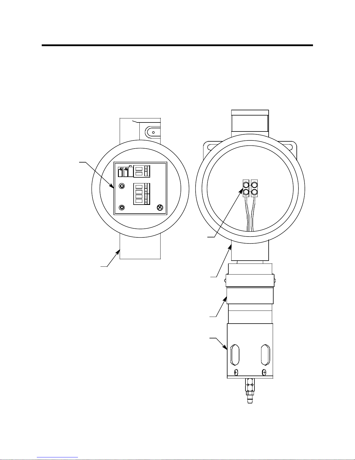
Description
TO XIC OX Y
S
SIG/PWR
Terminal Strip
Amplifier
Detector J-Box
Oxygen Detector
SPAN
ZERO
Amplifier J-Box
Calibration Adapter/Splash Guard
This section describes the components of the oxygen transmitter. The transmitter is a 4 - 20
mA type detector head. It consists of the oxygen detector, calibration adapter/splash
guard, amplifier, the amplifier junction box, and the detector junction box. The twojunction-box configuration is intended for situations where the detector needs to be
installed at an inaccessible location. The detector junction box can be installed at the
inaccessible location and the amplifier junction box can be installed in a more readily
accessible area.
6 • 65-2322-04SS Oxygen Transmitter
Figure 1: Component Location
Page 7
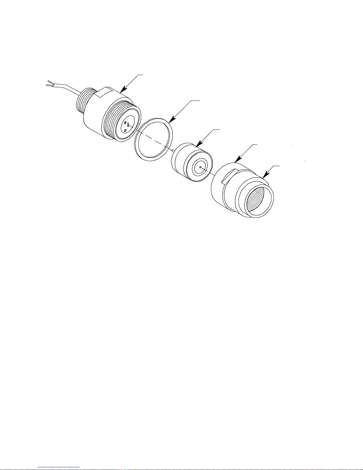
Oxygen Detector
Cap Gasket
Fl ame Arre stor
Guard
Det ect or Hou si ng Ca p
Plug-in Oxyge n Sensor
Detector HousingBody
The oxygen detector consists of the detector housing body, detector housing cap, cap
gasket, and the plug-in sensor.
Figure 2: Oxygen Detector Compon ent Location
Detector Housing Body
The detector housing body protects the electronic components within the housing. Use the
mounting threads at the top of the housing to screw the oxygen detector into the 3/4 NPT
hub on the bottom of the junction box. Two wires ext end fro m th e top of the detector
housing body. Use these wires to connect the oxygen detector to the amplifier. One of the
wires is white and one of the wires is green.
The housing includes two sockets installed on a circuit board. These sockets accept the
plug-in sensor’s two pins to provide electrical connection for the sensor. The circuit board
with the sockets conditions the sensor ’s signal before the signal reaches the amplifier.
Housing Cap & Cap Gasket
The housing cap screws onto the detector housing. It retains th e plug-in sensor and
protects it from damage. A foam gasket is installed inside the housing cap that seals
against the sensor fa ce. The ho using ca p also incl udes a flame arrestor which contai ns any
sparks that may occur within the detector and a flame arrestor guard which protects the
flame arrestor from damage. Unscrew the detector cap to access the plug-in sensor for
maintenance or replacement. A cap gasket seals the interface between the housing and
cap.
Plug-In Oxygen Sensor
The plug-in sensor is secured in th e detector assembly by the housin g cap. Through a
series of chemical and electrical reactions, the sensor produces a milli volt output that
corresponds to the detection range of the transmitter.
65-2322-04SS Ox yge n T ransmit ter • 7
Page 8

Calibration Adapter/Splash Guard
SIG/PWR
S
TOXIC OXY
Detector Terminal Strip
Controller Terminal Strip
SPAN
ZERO
+ Test Point (Red)
- Test Point (Black)
Factory Adjust Pot
Span Pot
Zero Pot
A calibration adapter/splash guard is installed on the oxygen detector. A fitting at the
bottom of the calibration adapter/splash guard allows a length of tubing to be connected
for calibration and routed to a more easily accessible location (near the amplifier junction
box is optimal for ease of calibration). The calibration adapter/splash guard also protects
the detector from splashing water or direct water spray.
Amplifier
The amplifier converts the electrical output from the sensor to a 4 to 20 mA signal that
corresponds to the detection range and transmits the signal to a gas monitoring controller.
A foam gasket that orients the amplifier and keeps it from rotating is instal led on the
bottom of the amplifier. The amplifier includes the controller terminal strip, detector
terminal strip, zero pot, span pot, and test points (Figure 3).
Controller Terminal Strip
The controller terminal strip is a two position plug-in style terminal strip located at the
top edge of the amplifier. Use the controller terminal strip to connect the amplifier to a
controller.
Detector Terminal Strip
The detector terminal strip is a four-point plug-in style terminal strip near the bottom of
the amplifier. Use the detector terminal strip to connect the oxygen detector to the
amplifier.
Zero Pot
The zero pot is located in the upper left corner of the amplifier (see Figure 3). Use a small
flat blade screwdriver to turn the zero pot’s adjustment screw and adjust the amplifier’s
zero (oxygen free) output during the calibration procedure. Turn the adjustment screw
clockwise to increase the zero output and counterclockwise to decrease the zero output.
8 • 65-2322-04SS Oxygen Transmitter
Figure 3: Amplifier Component Location
Page 9

Span Pot
The span pot is located to the right of the zero pot (see Figure 3). Use a small flat blade
screwdriver to turn the span pot’s adjustment screw and adjust the amplifier’s fresh air
output during the start up and calibration procedures. Turn the adjustment screw
clockwise to increase the output and counterclockwise to decrease the output.
CAUTION: The third potentiometer is factory-set. Do not adjust it.
Test Points
The test points (red and black) are on the left side of the amplifier (see Figure 3). The test
points produce a 100mV to 500 mV output that corresponds to the transmitter’s 4 to 20
mA output. Use the test points and a voltmeter to measure the transmitter’s output
during the start-up and calibration procedures. The black test point in the lower left
corner is the negative (-) test point and the red test point below the zero pot is the positive
(+) test point.
Amplifier Junction Box
The amplifier junction box protects the amplifier and wiring connections made to the
amplifier. Us e the top 3/4 NP T conduit hub to connect wiring from the amplifier to the
controller. Use the bottom 3/4 NPT conduit hub to wire the remotely installed oxygen
detector. Use the cover on the front of the junction box to access the interior of the junction
box. The amplifier is factory installed in the junction bo x. Three spacers installed on the
back of the junction box control the distance of the junction box from a mounting surface.
Detector Junction Box
The stainless steel detector junction box is intended to be installed remotely from the
amplifier junction box. The oxygen detector is factor y installed in the bottom 3/4 NPT
conduit hub. A terminal strip is provided for wiring conn ections and the detector is
factory wired to one side of this terminal strip. The other side of the terminal strip is for
user-supplied wiring to the detector terminal strip located in the amplifier junction box.
This wiring should go through the top 3/4 NPT conduit hub. An O-ring seals the interface
between the junction box cover and the junction box base.
A cover on the front of the junction box allows access to the interior of the junction box. A
locking set screw on the junction box cover allows you to secure the junction box cover
and prev ent it from being removed.
65-2322-04SS Ox yge n T ransmit ter • 9
Page 10

Installation
2.70 .38
Ø3.65
3/4 Co nduit Hub
3/4 Co nduit Hub
5.25
Rubber
Spacer,
3X
This section describes procedures to mount the oxygen transmitter in the monitoring
environment and wire the transmitter to a controller.
Mounting the Oxygen Transmitter
1. Select a mounting site that is representative of the monitoring environment. Consider
the following when you select the mounting site.
• For the amplifier junction box, select a site wh ere the jun ction box is not likely to
be bumped or disturbed. Make sure there is sufficient room to perform start-up,
maintenance, and calibration proced ures. The site should be easily accessible.
• For the detector junction box, select a site that is at breathing level.
• The junction boxes should be mounted no further than 200 feet from each other.
2. Amplifier junction box dimensions are shown in Figure 4. Detector junction box
dimensions are shown in Figure 5.
Figure 4: Amplifier Junction Box Dimensions
10 • 65-2322-04SS Oxygen Transmitter
Page 11

.20 Dia. x .4 5
Slot, 2X
3/4 NPT
Female,
2X
3.66
3.34
2.40
3.15
J-Bo x
11.35 max
1.10
Calibration Adapter/
Splash Guard
Oxygen Detector
Figure 5: Detector Junction Box Di men s ions
3. At the monitoring site you select, hang or mount the detector junction box with the
detector facing down (see Figure 5).
4. Install 3/16 inch I.D. flexible polyurethane tubing to the fitting at the bottom of the
calibration adapter/splash guard and route it to an accessible area that is close to the
amplifier junction box. See the “Parts List” on page 23 for available tubing.
65-2322-04SS Ox ygen Trans mit ter • 11
Page 12

Wiring the Detector to the Amplifier
WARNING: Always verify th at power to the controller is OFF before yo u make wiring
connections.
1. Confirm that no power is being applied to the amplifier. If the amplifier has already
been connected to a controller, turn off the controller and turn off or unplug power to
the controller.
2. Remove the detector junction box’s cover from the junction box.
3. Remove the amplifier junction box’s cover from the junction box.
4. Guide a two-conductor, shielded cable or two wires in conduit through the top
conduit hub of the detector junction box. To make wiring more convenient, use wire
colors that correspond to the detector wire colors: white and green.
NOTE: Consult RKI Instruments, Inc. for cable lengths longer than 200 feet.
5. Connect the wires to the terminal block in the detector junction box.
CAUTION: If shielded cable is used, leave the cable shield ’s drain wire disconnected and
insulated at the dete ctor junction bo x. You will connect the opposite e nd of the cabl e’s
drain wire to the amplifier junction box’s chassis (earth) ground.
6. Secure the detector junction box’s cover to the junction box.
7. Guide the other end of the two-conductor, shielded cable or two wires in conduit
through the bottom conduit hub of the amplifier junction box.
WARNING: To maintain the exp lo s io n proof classification of the oxygen detector/
junction box combination, a conduit seal must be used within 18 inches of
the detector junction box conduit hub used for wiring to the amplifier.
8. To gain access to a plug-in terminal strip for wiring, pull it out of its socket by
grasping the terminal strip and pulling. The detecto r strip is keyed so that the
controller and detector terminal strips cannot be reversed inadvertently.
9. Pull out the detector terminal strip and connect the two wires to the terminal strip as
follows (see Figure 6).
• Connect the wire corresponding to the detector’s white wire to the OXY “+”
terminal.
• Connect the wire corresponding to the detector’s green wire to the OXY “-”
terminal.
12 • 65-2322-04SS Oxygen Transmitter
Page 13

Green
White
White
Green
Detector J-Box
S
SIG/P W R
ZERO
SPAN
TOXIC OXY
Detector
Terminal S trip
Amplifier
Amplifier J-B ox
Cable
Shield
Calibration Adapter/Splash Guard
Oxyg en Detector
Figure 6: Wiring Detector to Amplifier
10. Reinstall the detector terminal strip into its socket.
11. Secure the amplifier junction box’s cover to the juncti on box.
12. If shielded cable is used, connect the cable’s drain wire to an available chassis (earth)
ground at the amplifier junction box. The amplifier mounting screw is a convenient
grounding location. Install a lug on the shield drain wire or wrap the shield drain wire
around the mounting screw. Do not connect the shield drain wire a t the detector
junction box.
65-2322-04SS Ox ygen Trans mit ter • 13
Page 14

Wiring the Amplifier to a Controller
1. Turn off the controller.
2. Turn off or unplug power to the controller.
3. Remove the amplifier junction box’s cover from the junction box.
4. Guide a two-conductor, shielded cable, or two wires in conduit through the top
conduit hub of the amplifier junction box.
WARNING: To maintain the explosion proof classification of the junction box
connection, a conduit seal must be used within 18 i nches of the amplifier
junction box conduit hub used for w ir i ng to the controller.
5. Pull out the controller terminal strip and connect the two wires to the terminal strip as
follows (see Figure 7).
• Connect the positive wire to the terminal labeled SIG/PWR “+” terminal.
• Connect the signal wire to the terminal labeled SIG/PWR “S” terminal.
CAUTION: If shielded cable is used, leave the cable shield ’s drain wire disconnected and
insulated at the amplifier junction box. You will conn ect the opposite end of the
cable’s drain wire to the controller’s chassis (earth) ground.
6. Reinstall the controller terminal strip into its socket.
7. Secure the amplifier junction box’s cover to the junction box.
8. Route the cable or wires leading from the amplifier junction box through one of the
conduit hubs at the controller housing.
WARNING: To maintain the explosion proof classification of the junction box
connection, a conduit seal must be used within 18 i nches of the controller
conduit hub used for wiring to the amplifier junction box.
CAUTION: Do not route power and transmitter wiring through the same controller conduit hub.
The power cabl e may disrupt the transmission of the transmitter signal to the
controller.
14 • 65-2322-04SS Oxygen Transmitter
Page 15

9. Connect the wires to the applicable detector/transmitter terminal strip at the
TOXIC OXY SIG/PWR
SPAN
ZERO
S
White
Gree n
S
Controller De tector/Trans mitter
Ter m in al s, Ty pical Designat io n s
+
Cable Shield
Amplifier J- Box
Controller or
Recording Device
controller as shown in Figure 7.
Start Up
Figure 7: Wiring the Amplifier to a Controller
10. If shielded cable is used, connect the cable’s drain wire to an available chassis (earth)
ground at the controller. RKI controllers typically have a ground stud that can be used
to ground the cable’s drain wire.
This section describes procedures to s tart up the oxygen transmitter and place the
transmitter into normal operation.
Introducing Incoming Power
1. Complete the installation procedures described earlier in this manual.
2. Verify that the power wiring to the controller is correct and secure. Refer to the
3. Turn on power to the controller.
4. Turn on the controller.
5. Verify that the controller is on and operating properly. Refer to the controller
controller operator’s manual.
operator’s manual.
65-2322-04SS Ox ygen Trans mit ter • 15
Page 16

NOTE: When first powered up, the transmitter will enter about a one minute period
when the 4-20 mA output is stabilizing and may be well above or below the fresh
air reading momentarily. RKI controllers have a one min u te warmup period
when the controller does not display an y gas reading or give any alarm
indication. The oxygen transmitter’s 4-20 mA signal should be stable by the time
the controller’s warmup period is over.
CAUTION: Allow the transmitter to warm up for 5 minutes before you continue with the next
section, “Setting the Fresh Air Sign al”.
Setting the Fresh Air Signal
WARNING: Do not remove the detector housing cap or either of the junction box covers
while the circuits are energized unless the area is determined to be nonhazardous. Keep the detector housing cap and junction box covers tightly
closed during operation.
NOTE: If you can verify that the detector is in a fresh air environment (environment
known to be of normal oxygen content and free of toxic and combustible gase s),
it is not necessary to apply zero air when verifying or setting the fresh air
reading.
The procedure below describes applying zero emission air, usually called zero air, using a
calibration kit that includes cali bration gas and a fixed flow regulator with an on/off
knob. RKI Instruments, Inc. recommends using a 0.5 LPM (liters per minute) fixed flow
regulator.
1. Unscrew and remove the amplifier junction box’s cover from the junction box.
2. Set a voltmeter to measure in the millivolt (mV) range.
3. Plug the voltmeter leads into the test points on the amplifier. Plug the positive lead
into the red (+) test point; plug the negative lead into the black (-) test point.
4. Screw the regulator into the zero air calibration cylinder.
5. Use the flexible tubing coming from the calibratio n adapter/splash guard to connect
the regulator to the calibration cup.
6. Turn the regulator’s on/off knob counterclockwise to open it. Gas will begin to flow.
7. Allow the gas to flow for the length of time determined in “Determining Response
Time” on pag e 20.
8. Verify a voltmeter reading of 434 mV (±2 mV).
9. If necessary, use a small flat-blade screwdriver to adjust the span pot until the
voltmeter reading is 434 mV (±2 mV).
10. Turn the regulator’s on/off knob clockwise to close it.
11. Disconnect the calibration adapter/splash guard’s flexible tubing from the regulator.
NOTE: Do not disconnect the flexible tubing from the calibration ada p ter/splash guard.
16 • 65-2322-04SS Oxygen Transmitter
Page 17

12. Unscrew the regulator from the zero air calibration cylinder.
13. Store the components of the calibration kit in a safe and convenient place.
14. Remove the voltmeter leads from the test points.
15. Secure the amplifier junction box cover to the junction box.
Maintenance
This section describes maintenance procedures. It includes preventive maintenance,
troubleshooting, and component replacement procedures.
Preventive Maintenance
This section describes a preventive maintenance schedule to ensure the optimum
performance of the oxygen transmitter. It includes daily and quarterl y proced ures.
Daily
Verify a display reading of 20.9% volume oxygen at the controller. Investigate significant
changes in the display reading.
Quarterly
Calibrate the oxygen transmitter as described in “Calibration” on page 21. See the
calibration frequency discussion in “Ca libration Frequency” on page 20 to de termine if a
quarterly calibration schedule fits you r needs.
Troubleshooting
The troubleshooting guide describes symptoms, probable causes, and recommended
action for problems you may encounter with the oxy gen transmitter.
NOTE: This troubleshooting guide describes transmitter problems on ly. See the
controller operator’s manual for problems you may encounter with the
controller.
Table 2: Trouble shooting the Oxygen Transmitter
Condition Symptom(s) Probable Causes Recommended Action
Fail Condition • Controller indicates a
fail condition.
• The detector-toamplifier or amplifierto-controller wiring is
disconnected or
misconnected.
• The plug-in sensor is
not properly plugged
into the sockets in the
detector housing body.
• The transmitter’s fresh
air reading is low
enough to cause a fail
condition.
• The transmitter is
malfunctioning.
1. Verify that the detector-to-amplifier
and amplifier-to-controller wiring is
correct and secure.
2. Confirm that the plug-in sensor is
installed properly.
3. Perform a fresh air adjustment. A full
calibration is recommended.
4. If the fail condition continues, replace
the plug-in sensor as described later
in this section.
5. If the fail condition continues, contact
RKI for further instruction.
65-2322-04SS Ox ygen Trans mit ter • 17
Page 18

Condition Symptom(s) Probable Causes Recommended Action
Slow or No
Response/
Difficult or
Unable to
Calibrate
• Unable to accurately
set the fresh air or
zero reading during
calibration.
• Transmitter requires
frequent calibration.
Note: Under “normal”
circumstances, the
transmitter requires
calibration once every 3
months.
Some applications
may require a more
frequent calibration
schedule.
• The calibration cylinder
is low, out-dated, or
defective.
• The flame arrestor in
the detector housing
cap is wet or clogged
with dirt or other
particulates.
• The calibration gas is
not an appropriate
concentration.
• The transmitter is
malfunctioning.
• The flexible tubing to
the calibration adapter/
splash guard has
become kinked,
blocked, or
disconnected.
1. Verify that the calibration cylinder
contains an adequate supply of a
fresh test sample.
2. Check the detector housing cap to
determine if the flame arrestor is wet
or dirty. Clean if necessary.
3. Verify that the calibration gas
concentration is appropriate for the
transmitter. Zero emission air (20.9%
oxygen) is normally used for a fresh
air adjustment if the environment is
suspect and 100% nitrogen (0%
oxygen) is normally used for a zero
adjustment.
4. Verify that the flexible tubing to the
calibration adapter/splash guard is
clear and connected to the calibration
adapter/splash guard.
5. If the calibration/response difficulties
continue, replace the plug-in sensor
as described later in this section.
6. If the calibration/response difficulties
continue, contact RKI for further
instruction.
Replacing Components of the Oxygen Transmitter
This section includes a procedure to replace the oxygen plug-in sensor, the oxygen
detector assembly, and the amplifier. In most cases, it is not necessary to replace the entire
detector assembly.
Replacing the Plug-In Oxygen Sensor
CAUTION: The sensor contains electrolyte which is a dilute acid. Do not disassemble the sensor
when replacing it with a new one. If sensor electrolyte comes in contac t with your
skin, wash affected area thoroughly with soap and water.
1. Turn off the controller.
2. Turn off or unplug power to the controller.
3. Unscrew the detector housing cap from the detector housing body. Make sure not to
lose the cap gasket.
4. Unplug and remove the oxygen sensor.
5. Carefully plug the replacement sensor into the socket pattern that is located in the
detector housing.
6. Make sure the cap gasket is in place and screw the detector housing cap back onto the
detector housing body.
7. Turn on or plug in power to the controller.
8. Turn on the controller and place into normal operation.
CAUTION: Allow the replacement sensor to warm up for 5 minutes before you continue with the
next step.
18 • 65-2322-04SS Oxygen Transmitter
Page 19

9. Calibrate the transmitter as described in the “Calibration” on page 21.
Replacing the Oxygen Detector
NOTE: In most cases, it is only necessary to replace the plu g- in oxygen sensor.
1. Turn off the controller.
2. Turn off or unplug power to the controller.
3. Unscrew the calibration ada pter/splash guard from the detector.
4. Remove the detector junction box’s cover from the junction box.
5. Remove the detector terminal strip from its socket.
6. Disconnect the detector leads from the detector terminal strip. Note the position of the
color-coded leads as you remove them.
7. Unscrew the detec tor from the detector ju nc tion box conduit hub.
8. Guide the detector leads of the replacement detector through the bottom conduit hub
of the detector junction box, then screw the mounting threads of the detector int o th e
conduit hub. If necessary for environ mental c onditions , apply th read seal ant or Teflo n
tape to the hub and/or detector threads to seal them.
9. Connect the detector leads to the appropriate detector terminal strip terminals.
Connect the wire corresponding to the detector’s white wire to the terminal labeled
OXY “+” and the wire corresponding to the detector’s green wire to the terminal
labeled OXY “-”. See Figure 6 for the detector wiring connections to the amplifier.
10. Screw the calibration adapter/splash guard onto the new detector.
11. Reinstall the detector terminal strip into its socket.
12. Reinstall the detector junction box cover.
13. Turn on or plug in power to the controller.
14. Turn on the controller and place it into normal operation.
CAUTION: Allow the replacement detector to warm up for 5 minutes before you continue with
the next step.
15. Calibrate the replacement detector as described in “Calibration” on page 21.
Replacing the Amplifier
NOTE: The amplifier is not housed in the same junction box as the oxygen detector. The
amplifier junction box should be somewhere accessible.
1. Turn off the controller.
2. Turn off or unplug power to the controller.
3. Remove the amplifier junction box’s cover.
4. Unplug the detector terminal strip and controller terminal strip from their sockets.
You may leave the wires connected to the terminal strips.
5. Unscrew and remove the screw with the flat and lock washers that secures the
amplifier to the junction box. The screw is at the bottom right of the amplifier.
6. Remove the old amplifier.
65-2322-04SS Ox ygen Trans mit ter • 19
Page 20

7. Place the new amplifier in the same position as the old amplifier. A foam gasket that
orients the amplifier and keeps it from rotatin g is installed on the bottom of the
amplifier. Make sure the amplifier is seated flat in the junction box.
8. Install the new amplifier into the junction box with the screw, lock washer, and flat
washer you removed in Step 5.
9. Install the detector and controller terminals strips into their sockets on the new
amplifier as shown in Figure 6 and Figure 7. If controller leads or detector leads were
removed during this procedure, refer to Figure 6 and Figure 7 for the detector and
amplifier connections.
NOTE: When a transmitter is first powered up with a new amplifier, the initial output
may be either high or low depending on the setti ng of the span pot. Be sure to
make arrangements so that this does not cause unwanted alarms.
10. Reinstall the amplifier junction box cover.
11. Turn on or plug in power to the controller.
12. Turn on the controller and place it into normal operation.
13. Allow the transmitter to warm up for 5 minutes.
14. Calibrate the oxygen transmitter as described in the “Calibration” on page 21.
Calibration Frequency
Although there is no particular calibration frequency that is correct for all applica tions, a
calibration frequency of every 3 months is adequate for most oxygen transmitter
applications. Unless experience in a particular application dictates otherwise, RKI
Instruments, Inc. recommends a calibration frequency of every 3 months for the oxygen
transmitter.
If an application is not very demanding, for example detection in a clean, temperature
controlled environment, and calibration adjustments are minimal at calibration, then a
calibration freque ncy of every 6 months is adequate.
If the application is very demanding, for example if the environ ment is not well
controlled, then more frequent calibration than every 3 months may be necessary.
Determining Response Time
Since the detector junction box is installed remotely from the amplifier, the response time
of the detector will depend on the length of flexible tubing that is attached to the
calibration adapter/splash guard. To determine the response time based on the leng th of
tubing connected:
1. Place the controller into its calibration mode or disable external alarms.
2. Note the current gas reading displayed at the controller.
3. Screw the regulator into the calibration cylinder. Do not use a zero air cylinder for this
operation.
4. Use the flexible tubing coming from the calibratio n adapter/splash guard to connect
the regulator to the calibration cup.
20 • 65-2322-04SS Oxygen Transmitter
Page 21

Calibration
5. Turn the regulator’s on/off knob counterclockwise to open the regulator. Gas will
begin to flow. Take note of the time or start a stopwatch.
6. When you first start to notice an increase in the gas reading, note how much time
passed between starting the gas flow and noticing a readi ng re sponse.
7. Turn the regulator’s on/off knob clockwise to close the regulator.
8. Unscrew the regulator from the calibration cylinder.
9. Disconnect the calibration adapter/splash guard’s flexible tubing from the regulator.
NOTE: Do not disconnect the flexible tubing from the calibration ada p ter/splash guard.
10. Add 1 minute to the length of time determined in Step 6. This is the response time for
the detector. When performing a fresh air adjustment or zero adj ustment, gas m ust be
applied for this length of time.
This section describes how to calibrate the oxygen transmitter. It includes procedures to
prepare for calibration, set the fresh air reading, set the zero reading, and return to normal
operation. It describes the test using a calibrat ion kit that includes calibration gas and a
fixed flow regulator with an on/off knob. RKI Instruments, Inc. recommends using a 0.5
LPM (liters per minute) fixed flow regulator.
Preparing for Calibration
NOTE: Calibrating the oxygen transmitter may cause alarms. Be sure to put the
controller into its calibration program or disable external alarms before
calibration.
WARNING: Do not remove the detector housing cap or either of the junction box covers
while the circuits are energized unless the area is determined to be nonhazardous. Keep the detector housing cap and junction box covers tightly
closed during operation.
1. Unscrew and remove the amplifier junction box’s cover.
2. Set a voltmeter to measure in the millivolt (mV) range.
3. Plug the voltmeter leads into the test points on the amplifier. Plug the positive lead
into the red (+) test point; plug the negative lead into the black (-) test point.
4. Use the following formula to determine the correct test points outpu t for the
calibrating sample.
Output (mV) = (calibrating sample/fullscale) X 400 + 100
The concentration of oxygen in the atmosphere is 20.9%, so when setting the fresh air
reading, you will set the test points output to 434 mV (±2 mV).
434(mV) = (20.9/25) X 400 +100
65-2322-04SS Ox ygen Trans mit ter • 21
Page 22

5. Place the controller into its calibration mode or disable external alarms.
NOTE: Calibrating the oxygen transmitter may cause alarms. Be sure to put the
controller into its calibration mode or disable external alarms before continuing.
Setting the Fresh Air Reading
NOTE: If you can verify that the oxygen transmitter is in a fresh air environment, you do
not need to apply zero air to the detector before adjusting the fresh air reading.
1. Screw the regulator into the zero air calibration cylinder.
2. Use the flexible tubing coming from the calibratio n adapter/splash guard to connect
the regulator to the calibration cup.
3. Turn the regulator knob counterclockwise to open the regulator.
4. Allow the gas to flow for the length of time determined in “Determining Response
Time” on pag e 20.
5. Verify a reading of 434 mV (± 2mV). If necessary, use the span pot on the amplifier to
adjust the reading to 434 mV (± 2mV).
6. Unscrew the regulator from the zero air calibration cylinder.
7. Leave the calibration adapter/splash guard’s flexible tubing connected to th e
regulator.
Setting the Zero Reading
1. Screw the regulator into the calibration cylinder. Verify that the calibration gas is
representative of the transmitter’s target gas.
2. Turn the regulator knob counterclockwise to open the regulator.
3. Allow the calibration gas to flow for the length of tim e det e rmined in “Determining
Response Time” on page 20.
4. Verify a rea ding of 100 mV (± 2mV). If necessary, use the zero pot on the amplifie r to
adjust the reading to match the correct response reading.
5. Turn the regulator knob clockwise to close the regulator.
6. Unscrew the regulator from the calibration cylinder.
Returning to Normal Operation
1. Remove the voltmeter leads from the amplifier test points.
2. Disconnect the calibration adapter/splash guard’s flexible tubing from the regulator.
NOTE: Do not disconnect the flexible tubing from the calibration ada p ter/splash guard.
3. Secure the amplifier junction box’s cover to the junction box.
4. When the display reading rises above the decreasing alarm’s setpoint, return the
controller to normal operation.
5. Verify that the controller display reading decreases a nd stabilizes at 20.9% volume.
6. Store the components of the calibration kit in a safe and convenient place.
22 • 65-2322-04SS Oxygen Transmitter
Page 23

Parts List
Table 5 lists replacement parts and accessories for the oxygen transmitter.
Table 3: Parts List
Part Number Description
06-1248RK Sample tubing (order by the foot)
07-0033RK Detector housing cap gasket
07-7151RK O-ring for detector juncti on box
10-5153RK Lid-locking set screw for detector junction box
18-0416RK-11 Junction box with cover, stainless steel (for detector junction box)
18-0400RK-01 Junction box with rubber spacers (for am plifier junction box)
57-1064RK-01 S2 series oxygen amplifier with orienting gasket
65-2322-04SS Oxygen transmitter (includes detector, two junction boxes, and
amplifier), CSA classified
65-1025RK Oxygen plug-in sensor
65-2514RK Oxygen replacement detector assembly (includes plug-in sensor), CSA
classified
71-0481 65-2322-04SS Oxygen Transmitter Operator’s Manual (this document)
81-0076RK-01 Zero air calibration cylinder, 34 liter steel
81-0078RK-01 100% nitrogen calibration cylinder, 34 liter steel
81-0078RK-03 100% nitrogen cali bration cylinder, 103 liter
81-1050RK Regulator with gauge and knob, 0.5 LPM, for 17 liter and 34 liter steel
calibration cylinders (cylinders with external threads)
81-1051RK Regulator with gauge and kno b, 0.5 LPM, for 34 lit er aluminum, 58 lit er,
and 103 liter calibration cylinders (cylin ders with internal threads)
81-1116RK Calibration adapter/splash guard
65-2322-04SS Ox ygen Trans mit ter • 23
 Loading...