

Page 1

65-2302/65-2303
CT-7 Series
Toxic Detector
Operator’s Manual
Part Number: 71-0422
Revision: 0
Released: 6/26/18
www.rkiinstruments.com
Page 2

WARNING
Read and understand this instruction manual before operating
detector. Improper use of the detector could result in bodily harm
or death.
Periodic calibration and maintenance of the detector is essential
for proper operation and correct readings. Please calibrate and
maintain this detector regularly! Frequency of calibration
depends upon the type of use you have and the sensor types.
Typical calibration frequencies for most applications are between
3 and 6 months, but can be required more often or less often
based on your usage.
65-2302/65-2303 Toxic Detector
Page 3

Product Warranty
RKI Instruments, Inc. warrants gas alarm equipment sold by us to be free from defects in
materials, workmanship, and performance for a period of one year from date of shipment
from RKI Instruments, Inc. Any parts found defective within that period will be repaired
or replaced, at our option, free of charge. This warranty does not apply to those items
which by their nature are subject to deterioration or consumption in normal service, and
which must be cleaned, repaired, or replaced on a routine basis. Examples of such items
are:
Warranty is voided by abuse including mechanical damage, alteration, rough handling, or
repair procedures not in accordance with the operator’s manual. This warranty indicates
the full extent of our liability, and we are not responsible for removal or replacement costs,
local repair costs, transportation costs, or contingent expenses incurred witho u t our prior
approval.
a) Absorbent cartridges d) Batteries
b) Pump diaphragms and valves e) Filter elements
c) Fuses
THIS WARRANTY IS EXPRESSLY IN LIEU OF ANY AND ALL OTHER
WARRANTIES AND REPRESENTATIONS, EXPRESSED OR IMPLIED,
AND ALL OTHER OBLIGATIONS OR LIABILITIES ON THE PART OF
RKI INSTRUMENTS, INC. INCLUDING BUT NOT LIMITED TO, THE
WARRANTY OF MERCHANTABILITY OR F ITNESS FOR A
PARTICULAR PURPOSE. IN NO EVENT SHALL RKI INSTRUMENTS,
INC. BE LIABLE FOR INDIRECT, INCIDENTAL, OR CONSEQUENTIAL
LOSS OR DAMAGE OF ANY KIND CONNECTED WITH THE USE OF
ITS PRODUCTS OR FAILURE OF ITS PRODUCTS TO FUNCTION OR
OPERATE PROPERLY.
This warranty covers instruments and parts sold to users by authorized d istributors,
dealers, and representatives as appointed by RKI Instruments, Inc.
We do not assume indemnification for any a ccident or damage caused by the opera tion of
this gas monitor, and our warranty is limited to the replacement of parts or our complete
goods.
65-2302/65-2303 Toxic Detector
Page 4

Table of Contents
Overview . . . . . . . . . . . . . . . . . . . . . . . . . . . . . . . . . . . . . . . . . . . . . . . . . . . . . . . . . . . . . . . . . . . 1
Specifications. . . . . . . . . . . . . . . . . . . . . . . . . . . . . . . . . . . . . . . . . . . . . . . . . . . . . . . . . . . . . . . . 1
Description. . . . . . . . . . . . . . . . . . . . . . . . . . . . . . . . . . . . . . . . . . . . . . . . . . . . . . . . . . . . . . . . . . 2
65-2302 Toxic Detector. . . . . . . . . . . . . . . . . . . . . . . . . . . . . . . . . . . . . . . . . . . . . . . . . . . . . . . . . . . . . . . . . 2
Junction Box. . . . . . . . . . . . . . . . . . . . . . . . . . . . . . . . . . . . . . . . . . . . . . . . . . . . . . . . . . . . . . . . . . . . . . . . . . 3
Installation . . . . . . . . . . . . . . . . . . . . . . . . . . . . . . . . . . . . . . . . . . . . . . . . . . . . . . . . . . . . . . . . . . 3
Mounting the Toxic Detector . . . . . . . . . . . . . . . . . . . . . . . . . . . . . . . . . . . . . . . . . . . . . . . . . . . . . . . . . . . 3
Wiring the Toxic Detector to a Controller. . . . . . . . . . . . . . . . . . . . . . . . . . . . . . . . . . . . . . . . . . . . . . . . . 4
Startup. . . . . . . . . . . . . . . . . . . . . . . . . . . . . . . . . . . . . . . . . . . . . . . . . . . . . . . . . . . . . . . . . . . . . . 6
Introducing Incoming Power . . . . . . . . . . . . . . . . . . . . . . . . . . . . . . . . . . . . . . . . . . . . . . . . . . . . . . . . . . . 6
Setting the Zero (Fresh Air) Signal. . . . . . . . . . . . . . . . . . . . . . . . . . . . . . . . . . . . . . . . . . . . . . . . . . . . . . . 6
Maintenance. . . . . . . . . . . . . . . . . . . . . . . . . . . . . . . . . . . . . . . . . . . . . . . . . . . . . . . . . . . . . . . . . 7
Preventive Maintenance . . . . . . . . . . . . . . . . . . . . . . . . . . . . . . . . . . . . . . . . . . . . . . . . . . . . . . . . . . . . . . . 7
Troubleshooting . . . . . . . . . . . . . . . . . . . . . . . . . . . . . . . . . . . . . . . . . . . . . . . . . . . . . . . . . . . . . . . . . . . . . . 8
Replacing Components of the Toxic Detector . . . . . . . . . . . . . . . . . . . . . . . . . . . . . . . . . . . . . . . . . . . . . 9
Calibration Frequency . . . . . . . . . . . . . . . . . . . . . . . . . . . . . . . . . . . . . . . . . . . . . . . . . . . . . . . 12
Calibration . . . . . . . . . . . . . . . . . . . . . . . . . . . . . . . . . . . . . . . . . . . . . . . . . . . . . . . . . . . . . . . . . 12
Special Note About Calibrating a ClO2 Detector. . . . . . . . . . . . . . . . . . . . . . . . . . . . . . . . . . . . . . . . . . 12
Preparing for Calibration. . . . . . . . . . . . . . . . . . . . . . . . . . . . . . . . . . . . . . . . . . . . . . . . . . . . . . . . . . . . . . 12
Setting the Zero (Fresh Air) Reading. . . . . . . . . . . . . . . . . . . . . . . . . . . . . . . . . . . . . . . . . . . . . . . . . . . . 13
Setting the Response Reading (Span) . . . . . . . . . . . . . . . . . . . . . . . . . . . . . . . . . . . . . . . . . . . . . . . . . . . 13
Returning to Normal Operation. . . . . . . . . . . . . . . . . . . . . . . . . . . . . . . . . . . . . . . . . . . . . . . . . . . . . . . . 14
Parts List . . . . . . . . . . . . . . . . . . . . . . . . . . . . . . . . . . . . . . . . . . . . . . . . . . . . . . . . . . . . . . . . . . . 14
65-2302/65-2303 Toxic Detector
Page 5

Overview
This manual describes the 65-2302 and 65-2303 toxic detectors. This manual also describes
how to install, start up, maintain, and calibrate the toxic detector when used with a gas
monitoring controller. A parts list at the end of this manual lists replacement parts and
accessories for the toxic detector.
The 65-2303 toxic detector includes the 65-2302 toxic detector and a junction box.
The 65-2302 toxic detector does not include a junction box and is normally mounted in one
of a controller’s conduit hubs. I f you are using a 65-2302 toxic detector, disregard all
references to the junction box and junction box terminal strip.
The 65-2302 and 65-2303 detectors can be used for various target gases which are listed in
Table 1 below. For a particular target gas, the part number of the toxic detector will be of
the format 65-2302-XXX or 65-2303-XXX. For example, 65-2302-CLO2 is for chlorine
dioxide (ClO
Specifications
) detection.
2
WARNING: Do not use this product in a manner not specified in this instruction
manual.
Table 1 lists specifications for the various 65-2302/65-2303 toxic detectors.
Table 1: Specifications
Target Gas and Detection Range 65-2302-CL2/65-2303-CL2: Chlorine (Cl
65-2302-CL2-05/65-2303-CL2-05: Chlorine (Cl
65-2302-CL2-10/65-2303-CL2-10: Chlorine (Cl
65-2302-CLO2/65-2303-CLO2: Chlorine Dioxide (ClO
) 0 - 3.00 ppm
2
) 0 - 5.00 ppm
2
) 0 - 10.0 ppm
2
) 0 - 1.00 ppm
2
Sampling Method Diffusion
Accuracy ± 10% of reading or ± 5% of full scale (whichever is greater)
Response Time T90 in 60 seconds
Operating Temperature &
-4°F to 104°F (-20°C to 40°C)
Humidity
WARNING: When using the 65-2302/65-2303, you must follow the instructions and
warnings in this manual to assur e proper and safe operation of the
65-2302/65-2303 and to minimize the risk of personal injury. Be sure to
maintain and periodically calibrate the 65-2302/65-2303 as described in
this manual.
65-2302/65-2303 Toxic Detec tor • 1
Page 6
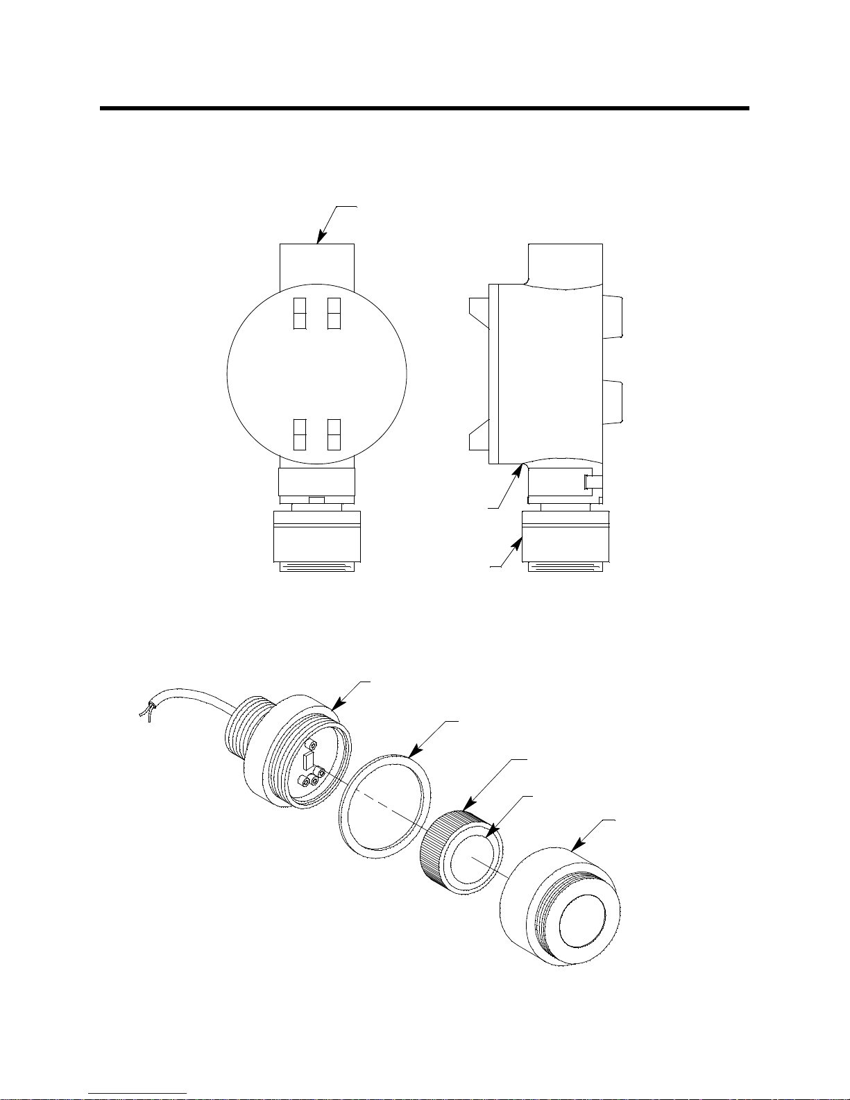
Description
3/4 NP T Conduit H ub
Detector
Juncti on Box
Plug- in Sen sor
(different for each detector type)
Detector
Housing Cap
VersaporRMembrane
Detector Housing Body
(di fferent for each detector type)
Cap Gasket
This section describes the components of the 65-2302 and 65-2303. The 65-2303 includes
the 65-2302 toxic detector and a juncti on box. The 65-23 02 does not i nclude a juncti on box.
Figure 1 below shows the components of the 65-2303.
65-2302 Toxic Detector
The 65-2302 toxic detector consists of the detector housing body, detector housing cap, cap
gasket, and the plug-in sensor.
Figure 1: 65-2303 Component Location
Figure 2: 65-2302 Toxic Detector Component Location
2 • 65-2302/65-2303 Toxic Detector
Page 7

Detector Housing Body
The detector housing body protects the electronic components within the housing. Use the
mounting threads at the top of the housing to screw the detector into a 3/4” NPT hub.
Two wires extend from the top of the detector housing body. Use these wires to connect
the detector to a controller. One of the wires is black and one of the wires is color-coded
depending on the detector type. See Figure 4 on page 5 for the color code assignments.
The housing body includes a four-socket pattern at the bottom of the housing body. The
plug-in sensor mates to this socket pattern. A pre-amplifier located between the sockets
and the two wires conditions the senso r ’s signal before the signal reaches the controller.
Each plug-in sensor type (Cl
different detector housing body for each gas type.
Housing Cap and Cap Gasket
The housing cap screws onto the detector housing. It retains the sensor an d protects it
from damage. A foam gasket inside the housing cap seals against the face of the sensor
when the cap is screwed on the housing body. Unscrew the detector cap to access the
sensor for replacement. A cap gasket seals the interface between the housing and cap.
Plug-in Sensor
The plug-in sensor is secured in the detector assembly by the housing cap. There is a
different sensor for each target gas. Through a series of chemical and electrical reactions,
the sensor produces an electrical output that corresponds to the detection range of the
sensor. A VersaporR membrane is installed on the sensor face for prote ction from water
and debris.
for example) requires a different pre-amplifier, so there is a
2
Installation
Junction Box
The junction box protects the detector wiring connections and allows you to install the
toxic detector at a mounting site that is remote from a controller. Two conduit hubs allow
you to mount the toxic detector to the junction box and connect the wi ring from the
detector to a controller. Three spacers installed on the back of the junction box control the
distance of the junction box from a mounting surface and ensure that there is enough
room to install a calibration cup on the detector during calibration. A terminal block
within the junction box facilitates the w iring connections. A cover on the front of the
junction box allows access to the interior of the junction box.
This section describes procedures to mount the toxic detector in the monitoring
environment and wire the detector to a controller.
Mounting the Toxic Detector
NOTE: If you are installing a 65-230 2, it does not include a junction box a nd is usually
factory installed in one of a controller’s conduit hubs or may be field installed
using the 3/4” NPT threads on the end with the wires. The 65-2303 includes a
junction box as shown in Figure 3 below.
1. Select a mounting site that is representative of the monitoring environment. Consider
the following when you select the mounting site.
• Select a site where the detector is not likely to be bumped or disturbed. Make sure
there is sufficient room to perform start-up, maintenance, and calibration
65-2302/65-2303 Toxic Detec tor • 3
Page 8

procedures.
.75
.38
Rubber
Spacer, 3X
3.10
3.65
Detector
7.30 .25
3/4" NPT
+
Ø1.75
11/2-20Threadfor
Calibration C up
65-2302 65-2303
Junction
Box
11/2-20Threadfor
Calibration Cu p
3/4 N PT
Conduit Hub
1.22
.75
6.70 Max
• Select a site where the target gas is likely to be found first.
NOTE: If your application does not require a specific mounting site, mount the detector
at approximately breathing level.
Figure 3: Outline & Mounting Dimensions, 65-2302 & 65-2303
2. At the mounting site you select, hang or mount the ju nction box with the detector
facing down (see Figure 3).
CAUTION: Mount the toxic detector with the detector facing down (see Figure 3.)
Wiring the Toxic Detector to a Controller
4 • 65-2302/65-2303 Toxic Detector
WARNING: Always verify th at power to the controller is OFF before yo u make wiring
1. Turn off the controller.
2. Turn off or unplug power to the controller.
3. If the detector is mounted remotely from a controller using the junction box, proceed
to step 4.
If the detector is mounted directly to a controller, connect the detector’s color-coded
and black wires to the appropriate controller detector terminals (see Figure 4 for the
color coding of the non-black wire) and skip to the Startup Section.
connections.
Page 9

4. Remove the junction box cover.
(+) See Table
S
+
Controller Housing
Controller Detector Terminals,
Typical Designations
Gas
TypeTable
CL2 yellow
CL2-05 yellow
CL2-10 yellow
CLO2 violet
Gas Type + Wire
0-3ppmCl2
Shielded
Cable
Black (S)
Detector
Terminal Strip
0 - 10 ppm Cl2
0-5ppmCl2
5. Guide a two-conductor, shielded cable or two wires in conduit through the unused
conduit hub of the junction box. Use appropriate conduit fittings and construction
technique for the environmental rating of the junction box. The junction box is rated
NEMA 4X.
6. Connect the two wires to the detector using the terminal block.
CAUTION: If using shielded cable, leave the drain wire insulated and disconnected at th e
detector. You will conn ect the opposite end of the cable’s drain wire at the c ontroller.
7. Secure the junction box cover to the junction box.
8. Route the cable or wires leading from the toxic detector through one of the conduit
hubs at the controller housing. Use appropriate conduit fittings and construction
technique for the environmental rating of the controller. RKI controllers are typically
rated NEMA 4X.
CAUTION: Do not route power and detector wiring through the same co nduit hub. The power
cable may disru pt the transmission of the detector signal to the controller.
9. Connect the wires to the applicable controller terminal strip. See the controller
operator’s manual and the controller’s detector head specification sheet for the
65-2302 or 65-2303 detector.
Figure 4: Wiring the Toxic Detector to a Controller
10. If using shielded cable, connect the cable’s drain wire to an available chassis ground at
the controller. RKI controllers typically have a ground stud that is a convenient
grounding location.
11. Reinstall the junction box cover.
65-2302/65-2303 Toxic Detec tor • 5
Page 10

Start Up
This section describes procedures to start up the toxic detector and place the detector into
normal operation.
Introducing Incoming Power
1. Complete the installation procedures described earlier in this manual.
2. Verify that the power wiring to the controller is correct and secure. Refer to the
controller operator’s manual.
3. Turn on or plug in the incoming power, then turn on the controller.
4. Verify that the controller is on and operating properly. Refer to the controller
operator’s manual.
CAUTION: Allow the detector to warm up for 15 minutes before you continue with the next
section, “Setting the Zero Reading”.
Setting the Zero (Fresh Air) Reading
CAUTION: If you suspect the presence of the target gas in the monit oring environment, use the
calibration kit and a zero air calibration cylinder to introduce “f re sh air” to the toxic
detector and verify an accurate zero setting.
CAUTION: Allow the detector to warm up for 15 minutes before setting the zero reading.
1. Verify a reading of 0 ppm at t he controller .
If the display reading is 0 ppm, start up is complete. The toxic detector is in no rmal
operation.
If the display reading is not 0 ppm, continu e w ith step 2 or step 3, depending on the
type of environment the detector is installed in.
2. For a fresh air environment (an environment known to be free of toxic and
combustible gases, and of normal oxygen content, 20.9%), set the zero reading
according to the controller operator’s manual.
3. For a non-fresh a ir environment:
a. Screw the calibration cup onto the bottom of the detector.
b. Screw the regulator into the zero air calibration cylinder.
c. Use the sample tubing to connect the regulator to the calibra tion cup.
d. Follow the instructions in the controller operator’s manual for setting the zero
reading.
e. When the instructions call for applying zero air to the detector, turn the
regulator’s on/off knob counterclockwise to open it. Gas will begin to flow.
f. Allow the gas to flow for two minutes.
g. Set the fresh air reading accord ing to the controller operator’s manual.
h. Turn the regulator’s on/off knob clo c kwise to close it.
i. Unscrew the regulator from the calibration cylinder.
6 • 65-2302/65-2303 Toxic Detector
Page 11

Maintenance
This section describes maintenance procedures. It includes preventive maintenance,
troubleshooting, and component replacement procedures.
Preventive Maintenance
This section describes a preventive maintenance schedule to ensure the optimum
performance of the toxic detector. It includes daily, monthl y, and quarterly procedures.
Daily
Verify a display reading of 0 ppm at the controller. Investigate significant changes in the
display reading.
Monthly
This procedure describes a test to verify that the toxic detector responds properly to the
target gas. It describes the test using a calibration kit that includes a calibration cup,
calibration gas, sample tubing, and a fixed flow regulator with an on/off knob. RKI
Instruments, Inc. recommends using a 0.5 LPM (liters per minute) fixed flow regulator.
j. Unscrew the calibration cup from the detector. For convenience, leave the sample
tubing connected to the calibration cup and the regulator.
WARNING: Failure to use the recommended calibration cup and calibration gas flow
rate will result i n an inaccurate reading.
NOTE: Performing a response test on the toxic detector may cause alarms. Be sure to put
the controller into its calibration program or disable external a la r ms before
performing this test.
Preparing for the response test
1. Place the controller into its calibration program or disable external alarms.
2. Verify that the controller display reading for the channel you are testing is 0 ppm.
If the display reading is not 0 ppm, set the zero (fresh air) reading of the detector as
described in the Start Up section of this manual, then continue this procedure.
3. Screw the regulator into the calibration cylinder. Make sure the regulator is off. It is off
when the on/off knob is turned all the way clockwise.
NOTE: If you are performing a response test on a ClO2 detector, RKI Instruments, Inc.
recommends the use of a ClO
“Special Note About Calibrating a ClO
generator instead of a calibration cylinder. See
2
Detector” on page 12 for further
2
discussion.
4. Screw the calibration cup onto the bottom of the detector.
5. Use the sample tubing to connect the regulator to the calibration cup.
Performing the response test
1. Turn the regulator’s on/off knob counterclockwise to open the regulator (or start the
flow of gas from a generator). Gas will begin to flow.
65-2302/65-2303 Toxic Detec tor • 7
Page 12

2. Allow the gas to flow for two minutes, then verify that the reading is within ± 20% of
the cylinder gas concentration.
NOTE: If the reading is not within ± 20% of the correct response reading, calibrate the
detector as described in “Calibration” on page 12.
3. Turn the regulator’s on/off knob clockwise to close the regulator (or stop the flow of
gas from a generator).
4. Unscrew the regulator from the calibration cylinder.
5. Unscrew the calibration cup from the detector. Make sure that you do not loosen the
detector housing cap when you unscrew the calibration cup.
6. When the controller display reading falls below the alarm setpoints, return the
controller to normal operation.
Quarterly
Calibrate t h e toxic detect or as described in “Calibration” on page 12.
Troubleshooting
The troubleshooting guide describes symptoms, probable causes, and recommended
action for problems you may encounter with the toxic detector.
NOTE: This troubleshooting guide describes detector problems only. See the controller
operator’s manual for problems you may encounter with the controller.
Fail Condition
Symptoms
• The controller indicates a fail condition.
Probable causes
• The detector wiring is disconnected or misconnected.
• The plug-in sensor is not properly plugged into th e socket in the detector housing
body.
• The detector’s zero reading is low enough to cause a fail condition.
• The detector is malfunctioning.
Recommended action
• Verify that the detector wiring is correct and secure.
• Confirm that the plug-in sensor is installed properly.
• Perform a zero (fresh air) adjustment. A full calibration is recommended.
• If the fail condition continues, replace the plug-in sensor as described later in this
section.
• If the fail condition continues, contact RKI for further instruction.
Slow or No Response/Difficult or Unable to Calibrate
Symptoms
• The detector responds slowly or does not respond during the monthly response test.
• Unable to accurately set the zero or response reading during the calibra tion
8 • 65-2302/65-2303 Toxic Detector
Page 13

procedure.
• The detector requires frequent calibration.
NOTE: Under “normal” circumstances, the detector requires calibration once every three
months. Some applications may requ ire a more frequent calibration schedule.
See “Calibration Frequency” on page 12 for a discussion of the calibration
frequency.
Probable causes
• The plug-in sensor has be en replaced and the shorting jumper has not been removed.
• The calibration cylinder is low, out-dated, or defecti ve.
• The incorrect calibration cup or regulator is being used.
• The VersaporR mem brane on the plug-in sensor face is blocked with dirt or some
other particulate contamination.
• The detector is malfunctioning.
Recommended action
1. Confirm that the shorting jumper on the plug-in sensor pins has been removed.
2. Verify that the calibration cylinder contains an ade quate supply of gas.
3. Confirm that you are using the correct calibration cup and regulator. See “Parts List”
on page 14 for the required calibration cup and regulator.
4. Check the plug-in sensor face and remove any p ar ticulate contamination from the
VersaporR membrane if necessary. If the membrane appears saturated with
contamination or damaged, replace the membrane as described in “Replacing the
VersaporR Membrane” on page 10.
5. If the calibration/response difficulties continue, replace the plug-in sensor as
described later in this section.
6. If the calibration/response difficulties continue, contact RKI Instruments, Inc. for
further instruction.
Replacing Components of the Toxic Detector
This section includes a procedure to replace the plug-in toxic sensor, the VersaporR
membrane, and the entire toxic detector assembly. In most cases, it is not necessary to
replace the entire detector assembly.
Replacing the Plug-in Toxic Sens or
CAUTION: The plug-in sensor c ontai ns ele ctrolyt e whic h is a dil ute acid. Do not disa ssem ble the
sensor when replacing it with a new one. If sensor electrolyte comes in contact with
your skin, wash affected area thoroughly with soap and water.
1. Turn off the controller.
2. Turn off or unplug power to the controller.
3. Unscrew the detector housing cap from the detector housing body. Make sure not to
lose the cap gasket.
4. Unplug and remove the toxic sensor.
65-2302/65-2303 Toxic Detec tor • 9
Page 14

5. Remove the replacement sensor from its packaging and remove the wire jumper. This
Remove jumper
wire jumper is installed on the sensor pins for shipment or storage but must be
removed for the sensor to operate properly when installed in a detector.
WARNING: The toxic sensor will not operate properly if the wire jumper is not
removed.
Figure 5: Plug-In Sensor Jumper Removal
6. Carefully plug the replacement sensor into the four-socket pattern located in the
detector housing body.
WARNING: You must replace the plug-in sensor with the same type of sensor that is
installed. A detector cannot be converted from one type of detector to
another by using a different plug-in sensor. For example, if you are
replacing a Cl2 sensor, you must replace it with a Cl2 sensor.
7. Make sure the cap gasket is in place and screw the detector housing cap back onto the
detector housing body.
8. Turn on power to the controller.
9. Turn on the controller.
CAUTION: Allow the replacement sensor to warm up for 15 minutes before you continue with
the next step.
10. Calibrate the detector as described in “Calibration” on page 12.
Replacing the VersaporR Membrane
1. Turn off the controller.
2. Turn off or unplug incoming power to the controller.
3. Unscrew the detector housing cap from the detector housing body.
4. Unplug the plug-in sensor from the four-socket pattern in the detector housing body.
5. Gently pry up the edge of the white VersaporR membrane from the sensor face with a
small flat blade screwdriver or a similar tool.
6. Peel off the VersaporR membrane. It may be necessary to clean off the sensor face to
remove any residue left from the adhesive backed membrane.
7. Install the new membrane on the face of the plug-in sensor .
8. Plug the sensor back into the four-socket pattern in the detector housing body.
10 • 65-2302/65-2303 Toxic Detector
Page 15

9. Make sure the cap gasket is in place and screw the detector housing cap back onto the
detector housing body.
10. Turn on power to the controller.
11. Turn on the contro ller.
Replacing the Toxic Detector
NOTE: In most cases, it is only necessary to replace the plug-in sensor.
1. Turn off the controller.
2. Turn off or unplug incoming power to the controller.
3. If the detector is installed directly on a controller, open the controller door.
If the detector is installed remotely from a controller in a junction box, remove the
junction box cove r.
4. If the detector is installed directly on a controller, disconnect the detector leads from
the detector terminal strip in the controller. Note the position of the color-coded leads
as you remove them.
If the detector is installed remotely from a controller in a junction box , disconnect the
detector leads from the terminal block in the junction box. Note the position of the
color-coded leads as you remove them.
5. Unscrew the detector from the controller conduit hub or junction box conduit hub.
6. Guide the detector leads of the replacement detector through the controller conduit
hub or junction box conduit hub, then screw the mounting threads of the detector into
the hub. If necessary for environmental conditions, apply thread sealan t or Teflon tape
to the hub and/or detector threads to seal them.
7. If the detector is installed directly on a controller, connect the detector leads to the
appropriate detector terminal strip terminals. See Figure 4 on page 5 for wiring to a
generic controller. See the controller operator’s manual and the controller’s detector
head specification sheet for the 65-2302 or 65-2303 detector for wiring specific to your
controller.
If the detector is installed remotely from a controller in a junction box, co nnect the
detector leads to the terminal block the same way the old detector was wired (see
Figure 4 on page 5). See the controller operator’s manual and the controller’s detector
head specification sheet for the 65-2302 or 65-2303 to verify the connections to the
controller are correct.
8. If the detector is installed remotely from a controller in a junction box, reinstall the
junction box cove r.
9. Turn on or plug in power to the controller.
10. Turn on the contro ller.
CAUTION: Allow the replacement detector to warm up for 15 minutes before you continue with
the next step.
11. Calibrate the replacement detector as described in “Calibration” on page 12.
65-2302/65-2303 Toxic Detector • 11
Page 16

Calibration Frequency
Although there is no particular calibration frequency that is correct for all applica tions, a
calibration freque nc y of every 3 months is adequate for most toxic d etector applications.
Unless experience in a particular application dictates otherwise, RKI In struments, Inc.
recommends a calibration frequency of every 3 months for the toxic detector.
If an application is not very demanding, for example detection in a clean, temperature
controlled environment where toxic gas is not normally present, and calibration
adjustments are minimal at calibration, then a calibration freque ncy of every 6 months is
adequate.
If an application is very demanding, for example if the environment is not well controlled
or if toxic gas is often present, then more frequent calibration than every 3 months may be
necessary.
Calibration
This section describes how to calibrate the toxic detector. It includes procedures to prepare
for calibration, set the fresh air reading, set the response reading, and return to normal
operation. It describes calibration using a calibration kit that includes a calibration cup,
calibration gas, sample tubing, and a fixed flow regulator with an on/off knob. RKI
Instruments, Inc. recommends using a 0.5 LPM (liters per minute) fixed flow regulator.
WARNING: RKI Instruments, Inc. recommends that you dedicate a regulator for use
with chlorine (Cl
any other gases, particularly hydrogen sulfide (H2S).
WARNING: Not using the recommended calibration cup and sample flowrate will
result in an inaccurate calibration. See“Parts List” on page 14 for the
required calibration cup and regulator.
) gas and that you do not use that dedicated regulator for
2
Special Note About Calibrating a ClO2 Detector
RKI Instruments, Inc. recommends using a ClO2 generator to set the ClO2 detector’s
response reading. The flow rate on the generator needs to be set to 0.5 LPM and RKI
Instruments, Inc. recommends that 0.5 ppm ClO
calibration, the steps related to the use of a calibration gas cylinder in the instructions
below can be disregarded.
be used. If a ClO2 generator is used for
2
Preparing for Calibration
CAUTION: Confirm that the detector has been running for more than 15 minutes before
performing a calibration.
1. Screw the calibration cup onto the bottom of the detector.
2. Screw the regulator into the zero air calibration cylinder.
12 • 65-2302/65-2303 Toxic Detector
Page 17

3. Use the sample tubing to connect the regulator to the calibration cup.
NOTE If you can verify that the toxic detector is in a fresh air environment, you do not
need to apply zero air to the detector before adjusting the fresh air reading.
4. Put the controller into its calibration program. See the controller operator’s manual
for instructions to enter the calibration program.
Setting the Zero (Fresh Air) Reading
1. Follow the instructions in the con troller operator’s manual for setting the zero
reading.
2. When the instructions call for applyin g zero air to the detector, turn the regulator’s
on/off knob counterclockwise to open it . Gas will begin to flow.
3. Allow the gas to flow for two minutes.
4. Set the fresh air reading according to the controller operator’s manual.
5. Turn the regulator’s on/off knob clo ckwise to close it.
6. Unscrew the regulator from the zero air calibration cylinder. Leave the sample tubing
connected to the regulator and the calibration cup.
NOTE: Depending on the size of your zero air cylinder, it is possible that you will have a
different regulator for the zero air cylinder and toxic gas cylinder. If necessary to
fit the calibration toxic gas cylinder, change the regulator.
Setting the Response Reading (Span)
1. Screw the regulator into the calibration gas cylinder.
2. Follow the directions in the controller operator’s manual for setting the response
(span) reading.
3. When the directions call for exposing the detector to gas, turn the regula tor’s on/off
knob counterclockwise to open it (or start the flow of gas from a generator). Gas will
begin to flow.
4. Allow the gas to flow to the detector for 2 minutes.
5. Set the response reading according to the controller operator’s manual.
6. After setting the response reading, turn the regulator’s on/off knob clockwise to turn
it off (or stop the flow of gas from a generator).
7. Unscrew the regulator from the cylinder.
8. Unscrew the calibration cup from the detector. Make sure that you do not loosen the
detector housing cap when you unscrew the calibration cup.
NOTE: For convenience, leave the regulator and calibration cup connected by the
sample tubing.
65-2302/65-2303 Toxic Detector • 13
Page 18

Returning to Normal Operation
1. Allow about 45 seconds for the gas reading to decrease below the alarm points and
then return the controller to normal operation.
NOTE: If you do not allow the gas reading to decrease below the alarm points, then
unwanted alarms may occur.
2. Verify that the controller display reading d ecreases a nd stabilizes at 0 ppm.
3. Store the components of the calibration kit in a safe and convenient place.
Parts List
Table 2 lists replacement parts and accessories for the toxic detector.
Table 2: Parts List
Part Number Descripti o n
06-1283RK Calibration kit sample tubing, 3 foot T eflon w/flexible tubing on ends
07-0039RK Detector housing cap gasket
18-0400RK-01 Junction box with rubber spacers
33-0157RK VersaporR membrane for plug-in sensor face
65-2051-01 Replacement plug-in sensor, 0 - 3.00 ppm, 0 - 5.00 ppm, and 0 - 10.0 ppm Cl
with membrane
65-2052-01 Replacement plug-in sensor, 0 - 1.00 ppm ClO
65-2302-CL2 Replacement detector assembly, Cl
, 0 - 3.00 ppm range
2
, with membrane
2
(includes plug-in sensor)
65-2302-CL2-05 Replacement detector assembly, Cl
, 0 - 5.00 ppm range
2
(includes plug-in sensor)
65-2302-CL2-10 Replacement detector assembly, Cl
, 0 - 10.0 ppm range
2
(includes plug-in sensor)
65-2302-CLO2 Replacement detector assembly, ClO
, 0 - 1.00 ppm range
2
(includes plug-in sensor)
71-0422 65-2302/65-2303 Operator’s Manual (this document)
81-0076RK Zero air calibration cylinder, 17 liter steel
81-0076RK-01 Zero air calibration cylinder, 34 liter steel
,
2
81-0076RK-03 Zero air calibration cylinder, 103 lit er steel
81-0192RK-02 Calibration cylinder, 2 ppm Cl
calibrate all Cl
81-0192RK-04 Calibration cylinder, 2 ppm Cl
calibrate all Cl
14 • 65-2302/65-2303 Toxic Detector
ranges)
2
ranges)
2
in nitrogen, 58 liter, aluminum (can be used to
2
in nitrogen, 34 liter aluminum (can be used to
2
Page 19

Table 2: Parts List
Part Number Descripti o n
81-1050RK Regulator with gauge and knob , 0.5 LPM, for 17 liter and 34 li ter steel cali bration
cylinders (used for 34 liter zero air cylinder only)
81-1051RK Regulator with gauge and knob, 0.5 LPM, for 34AL/58/103 liter calibration
cylinders
81-1117RK Calibration cup
81-F605 Calibration kit, includes regulator, calibration cup, tubing, and 58 liter
aluminum calibration cylinder of 2 ppm Cl
in nitroge n
2
81-F605-LV Calibration kit, includes regulator, calibration cup, tubing, and 34 liter
aluminum calibration cylinder of 2 ppm Cl
in nitroge n
2
65-2302/65-2303 Toxic Detector • 15
 Loading...