

RKI Instruments 65-2301RKSS Series, 65-2301RKSS-ASH3, 65-2301RKSS-CL2, 65-2301RKSS-HCN, 65-2301RKSS-10 Operator's Manual
...Page 1

65-2301RKSS
Toxic Detector
Operator’s Manual
Part Number: 71-0273RK
Revision: A
Released: 7/17/19
www.rkiinstruments.com
Page 2

WARNING
Read and understand this instruction manual before operating
detector. Improper use of the detector could result in bodily harm or
death.
Periodic calibration and maintenance of the detector is essential for
proper operation and correct readings. Please calibrate and maintain
this detector regularly! Frequency of calibration depends upon the
type of use you have and the sensor types.
Typical calibration frequencies for most applications are between 3
and 6 months, but can be required more often or less often based on
your usage.
65-2301RKSS Toxic Detector
Page 3

Product Warranty
RKI Instruments, Inc. warrants gas alarm equipment sold by us to be free from defects in materials,
workmanship, and performance for a period of one year from date of shipment from RKI Instruments,
Inc. Any parts found defective within that period will be repaired or replaced, at our option, free of
charge. This warranty does not apply to those items which by their na ture are subject to deterioration
or consumption in normal service, and which must be cleaned, repaired, or replaced on a routine
basis. Examples of such items are:
Warranty is voided by abuse including mechanical damage, alteration, rough handling, or repair
procedures not in accordance with the operator’s manual. This warranty indicates the full extent of
our liability, and we are not responsible for removal or replacement costs, local repair costs,
transportation costs, or contingent expenses incurred without our prior approval.
THIS WARRANTY IS EXPRESSLY IN LIEU OF ANY AND ALL OTHER
WARRANTIES AND REPRESENTATIONS, EXPRESSED OR IMPLIED, AND ALL
OTHER OBLIGATIONS OR LIABILITIES ON THE PART OF RKI I NSTRUMENTS,
INC. INCLUDING BUT NOT LIMITED TO, THE WARRANTY OF
MERCHANTABILITY OR FITNESS FOR A PARTICULAR PURPOSE. IN NO
EVENT SHALL RKI INSTRUMENTS, INC. BE LIABLE FOR INDIRECT,
INCIDENTAL, OR CONSEQUENTIAL LOSS OR DAMAGE OF ANY KIND
CONNECTED WITH THE USE OF ITS PRODUCTS OR FAILURE OF ITS
PRODUCTS TO FUNCTION OR OPERATE PROPERLY.
a) Absorbent cartridges d) Batteries
b) Pump diaphragms and valves e) Filter elements
c) Fuses
This warranty covers instrumen ts and parts sold to users by authori zed distributors, dealers, and
representatives as appointed by RKI Instruments, Inc.
We do not assume indemnification for a ny accident or damage caused by the operation of this gas
monitor, and our warranty is limited to the replacement of parts or our complete goods.
65-2301RKSS Toxic Detector
Page 4

Table of Contents
Overview . . . . . . . . . . . . . . . . . . . . . . . . . . . . . . . . . . . . . . . . . . . . . . . . . . . . . . . . . . . . . 5
Specifications. . . . . . . . . . . . . . . . . . . . . . . . . . . . . . . . . . . . . . . . . . . . . . . . . . . . . . . . . . 5
Description. . . . . . . . . . . . . . . . . . . . . . . . . . . . . . . . . . . . . . . . . . . . . . . . . . . . . . . . . . . . 6
65-2300RK Toxic Detector . . . . . . . . . . . . . . . . . . . . . . . . . . . . . . . . . . . . . . . . . . . . . . . . . . . . . . 6
Junction Box . . . . . . . . . . . . . . . . . . . . . . . . . . . . . . . . . . . . . . . . . . . . . . . . . . . . . . . . . . . . . . . . . . 7
Installation . . . . . . . . . . . . . . . . . . . . . . . . . . . . . . . . . . . . . . . . . . . . . . . . . . . . . . . . . . . . 7
Mounting the Toxic Detector. . . . . . . . . . . . . . . . . . . . . . . . . . . . . . . . . . . . . . . . . . . . . . . . . . . . 7
Wiring the Toxic Detector to a Controller . . . . . . . . . . . . . . . . . . . . . . . . . . . . . . . . . . . . . . . . . 8
Startup. . . . . . . . . . . . . . . . . . . . . . . . . . . . . . . . . . . . . . . . . . . . . . . . . . . . . . . . . . . . . . . 10
Introducing Incoming Power. . . . . . . . . . . . . . . . . . . . . . . . . . . . . . . . . . . . . . . . . . . . . . . . . . . 10
Setting the Zero (Fresh Air) Signal . . . . . . . . . . . . . . . . . . . . . . . . . . . . . . . . . . . . . . . . . . . . . . 10
Maintenance. . . . . . . . . . . . . . . . . . . . . . . . . . . . . . . . . . . . . . . . . . . . . . . . . . . . . . . . . . 10
Preventive Maintenance. . . . . . . . . . . . . . . . . . . . . . . . . . . . . . . . . . . . . . . . . . . . . . . . . . . . . . . 10
Troubleshooting. . . . . . . . . . . . . . . . . . . . . . . . . . . . . . . . . . . . . . . . . . . . . . . . . . . . . . . . . . . . . . 11
Replacing Components of the Toxic Detector. . . . . . . . . . . . . . . . . . . . . . . . . . . . . . . . . . . . . 12
Calibration Frequency . . . . . . . . . . . . . . . . . . . . . . . . . . . . . . . . . . . . . . . . . . . . . . . . . 13
Calibration . . . . . . . . . . . . . . . . . . . . . . . . . . . . . . . . . . . . . . . . . . . . . . . . . . . . . . . . . . . 14
Preparing for Calibration . . . . . . . . . . . . . . . . . . . . . . . . . . . . . . . . . . . . . . . . . . . . . . . . . . . . . . 14
Setting the Zero (Fresh Air) Reading . . . . . . . . . . . . . . . . . . . . . . . . . . . . . . . . . . . . . . . . . . . . 15
Setting the Response Reading (Span). . . . . . . . . . . . . . . . . . . . . . . . . . . . . . . . . . . . . . . . . . . . 15
Parts List . . . . . . . . . . . . . . . . . . . . . . . . . . . . . . . . . . . . . . . . . . . . . . . . . . . . . . . . . . . . . 16
65-2301RKSS Toxic Detector
Page 5

Overview
This manual describes the 65-2301RKSS toxic detector. This manual also describes how to install, start
up, maintain, and calibrate the toxic detector when used with a gas monitoring controller. A parts list
at the end of this manual lists replacement parts and accessories for the toxic detector.
The 65-2301RKSS detector can be used for various target gases which are listed in Table 1 below. For a
particular target gas, the part number of the toxic detector will be of the format 65- 2301RKSS- XXX. For
example, 65-2301RKSS-NH3 is for ammonia (NH
Specifications
WARNING: Do not use this product in a manner not specified in this instruction manual.
Table 1 lists specifications for the various 65-2301RKSS toxic detectors.
) detection.
3
Table 1: Specifications
Target Gas 65-2301RKSS-ASH3: Arsine (AsH
65-2301RKSS-CL2: Ch lorine (Cl
65-2301RKSSCL-10: Chlorine (Cl
)
3
)
2
)
2
65-2301RKSS-HCN: Hydrogen Cyanide (HCN)
65-2301RKSS-NH3: Ammon i a (NH
65-2301RKSS-SO2: Sulphur Dioxide (SO
65-2301RKSS-PH3: Phos phi n e (PH
)
3
)
2
)
3
Sampling Method Diffusion
Detection Range AsH
: 0 - 1.50 ppm
3
: 0 - 3.00 ppm
Cl
2
Cl
: 0 - 10.0 ppm
2
HCN: 0 - 15.0 ppm
: 0 - 75.0 ppm
NH
3
: 0 - 6.00 pp m
SO
2
: 0 - 1.00 ppm
PH
3
Accuracy ± 10% of reading or ± 5% of full scale (whichever is greater)
Response Time • Cl
and NH3: T90 in 90 seconds
2
• All others: T90 in 45 seconds
Operating Temperature &
Humidity
• 14°F to 104°F (-10°C to 40°C)
• 20% to 90% Relative Humidity
WARNING: When using the 65-2301RKSS, you must follow the instructions and warnings in this
manual to assure proper and safe operation of the 65-2301RKSS and to minimize the
risk of personal injury. Be sure to maintain and periodically calibrate the 65-2301RKSS
as described in this manual.
65-2301RKSS Toxic Dete cto r • 5
Page 6
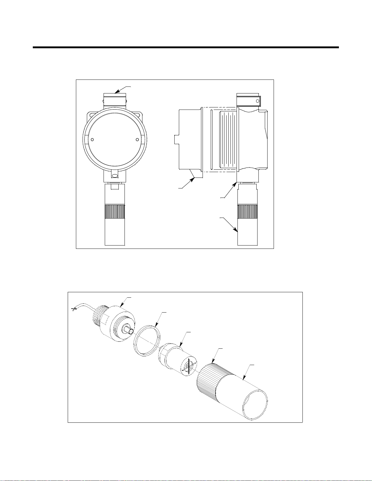
Description
3/4 NPT Conduit Hub
Sta inles s Stee l
Junct ion B ox
Tox ic Det ector
Locking Set Screw
Text Oriented
This Way
Splash Guard
(removable)
Sensor
(different for each d etector type)
Detect or Ho using
Cap
Cap Gasket
Det ector Housing B ody
(d iffer ent for ea c h d e t e c tor type )
This section describes the components of the 65-2301RKSS. The 65-2301RKSS includes the 65-2300RK
toxic detector and a junction box. Figure 1 below shows the components of the 65-2301RKSS.
Figure 1: 65-2301RKSS Component Location
65-2300RK Toxic Detector
The 65-2300RK toxic detector consists of the detector housing body, detector housing cap,
splashguard, cap gasket, and the plug- in sensor.
Figure 2: 65-2300RK Toxic Detector Component Location
6 • 65-2301RKSS Toxic Detector
Page 7

Detector Housing Body
The detector housing body protects the electronic components within the housing. Use the mounting
threads at the top of the housing to screw the toxic detector into a 3/4 NPT hub. Two wires extend
from the top of the detector housing body. Use these wires to connect the toxic detector to a controller.
One of the wires is black and one of the wires is color coded depending on the detector type. See
Figure 4 on page 9 for the color code assignments.
The housing body includes a 12 position connector at the bottom of the housing body. The plug-in
sensor mates to this connector. A pre-amplifier located between the connector and the two
interconnect wires conditions th e s ensor’s signal before the signal reaches the controller.
Housing Cap, Cap Gasket, & Splashguard
The housing cap screws onto the detector housing. It retains the sensor and protects it from damage. A
removable splashguard is screwed onto the detector cap to protect the sensor from impact dam ag e,
direct water spray, and splashing. Unscrew the detector cap to access the sensor for maintenance or
replacement. A cap gasket seals the interface between the housing and cap.
Plug-in Sensor
The plug-in sensor is secured in the detector assembly by the housing cap. There is a different sensor
for each target gas. Through a series of chemical and electrical reactions, the sensor produces an
electrical output that corresponds to the detection range of the sensor.
Junction Box
The stainless steel, corrosion resistant junction box allows you to install the detector at a mounting site
that is remote from a controller, and it protects the detector wiring connections. Two conduit hubs
allow you to mount the detector to the junction bo x and connect the wiring from the detector to a
controller. An O-ring seals the interface between the junction box cover and the junction box base.
The terminal block within the junction box facilitates the wiring process. A cover on the front of the
junction box allows access to the interior of the junction box. A locking set screw on the junction box
cover allows you to secure the junction box cover and prevent it from being removed.
Installation
This section describes procedures to mount the toxic detector in the monitoring environment and wire
the detector to a controller.
Mounting the Toxic Detector
1. Select a mounting site that is representative of the monitoring environment. Con sider the
NOTE: If your application does not require a specific mounting site, mount the detector at
following when you select the mounting site.
• Select a site where the detector is not likely to be bumped or disturbed. Make sure there is
sufficient room to perf orm start-up, maintenance, an d calibration procedures.
• Select a site where the target gas is likely to be found first.
approximately breathing level.
65-2301RKSS Toxic Dete cto r • 7
Page 8
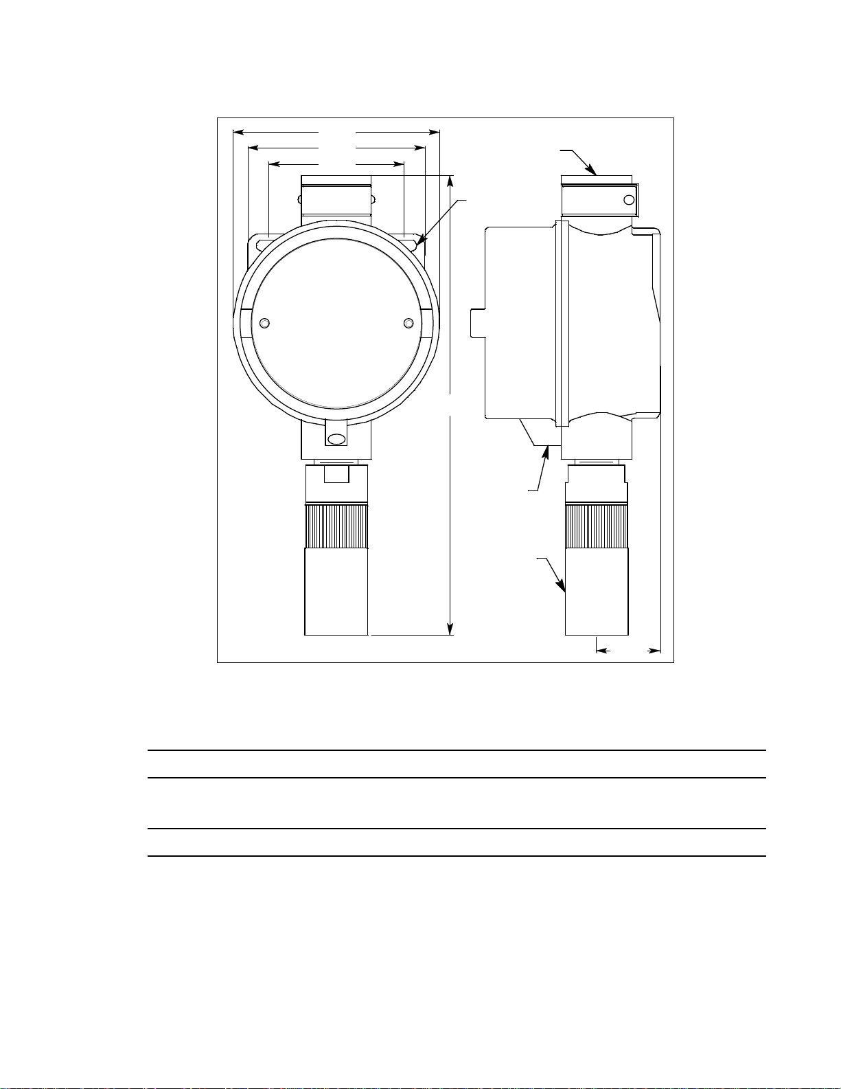
2.40
3.15
3.66
Tex t Orie nted
This Way
Junction
Box
Toxic
Detector
.20 Dia. x .45
Slot, 2X
3/4 NPT
Conduit H ub
10.00 Max
1.10
Figure 3: Outline & Mounting Dimensions, 65-2301RKSS
2. At the mounting site you select, hang or mount the junction box with the detector facing down
(see Figure 3).
CAUTION: Mount the toxic detector with the detector facing down (see Figure 3.)
Wiring the Toxic Detector to a Controller
WARNING: Always verify that power to the controller is OFF before you make wiring connections.
1. Turn off the controller.
2. Turn off or unplug power to the controller.
3. Remove the junction box cover.
4. Guide a two-conductor, shielded cable or two wires in conduit through the unused conduit hub of
the junction box.
8 • 65-2301RKSS Toxic Detector
Page 9
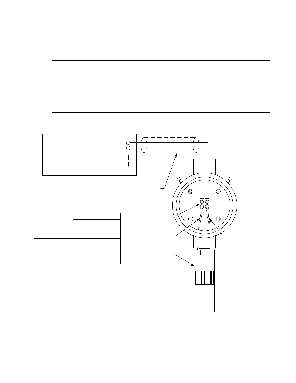
5. Connect the two wires to the detector using the terminal block.
(+) See T able
S
+
Controller Housing
Control ler De tector Termi nals,
Typical Designations
Gas
Type Table
AsH3 brown
CL2 yellow
CL-10 yellow
HCN white
NH3 red
PH3 green
SO2 blue
Gas T ype + Wi re
0-10ppmCl2
0-3ppmCl2
Shie lded Cable
ESM-01 Detector
Black (S)
Terminal Strip
CAUTION: If using shielded cable, leave the drain w i re insulated and disconnected at the de tector. You will
connect the opposite end of the cable’s drain wire at the cont ro ller.
6. Secure the junction box cover to the junction box.
7. Route the cable or wires leading from the toxic detector through one of the conduit hubs at the
controller housing. Use appropriate conduit fittings and construction technique for the
environmental rating of the controller. RKI controllers are typically rated NEMA 4X.
CAUTION: Do not route power a nd detector wiring through the same c onduit hub. The powe r cable may
disrupt the transmission of the detector signal to the controller.
8. Connect the wires to the applicable controller terminal strip. See the controller operator’s manual
and the controller’s detector head specification sheet for the 65-2301RKSS detector.
9. If using shielded cable, connect the cable’s drain wire to an available chassis ground at the
controller. RKI controllers typically have a groun d stud that is a convenient grounding location.
10. Reinstall the junction box cover.
Figure 4: Wiring the Toxic Detector to a Controller
65-2301RKSS Toxic Dete cto r • 9
Page 10

Start Up
This section describes procedures to start up the toxic detector and place the detector into normal
operation.
Introducing Incoming Power
1. Complete the installation procedures described earlier in this manual.
2. Verify that the power wiring to the controller is correct and secure. Refer to the controller
operator’s manual.
3. Turn on or plug in the incoming power, then turn on the controller.
4. Verify that the controller is on and operating properly . Refer to the controller operator’s manual.
CAUTION: Allow the detector to warm up for 5 minutes before you continue with the next section, “Setting
the Zero Reading”.
Setting the Zero (Fresh Air) Reading
CAUTION: If you suspect the presence of the tar get ga s in the monit orin g env ironm ent, use th e cali brati on kit
and a zero air calibration cylinder to introduce “fresh air” to the toxic detector and verify an
accurate zero se tting. See “Calib ra tion” on page 14 for instructions to introduce zero air to the
detector.
1. Verify that the detector is in a fresh air enviro nment (environment known to be free of toxi c and
combustible gases, and of normal oxygen content, 20.9%).
2. Verify a reading of 0 ppm at t he controller .
3. Perform a zero (fresh air) adjustment operation at the controller. See the controller operator’s
manual for instructions.
Maintenance
This section describes maintenance procedures. It includes preventive maintenance, troubleshooting,
and component replacement procedures.
Preventive Maintenance
This section describes a preventive maintenance schedule to ensure the optimum performance of the
toxic detector. It includes daily and quarterly procedur es.
Daily
Verify a display reading of 0 ppm a t the controller. Investigate significant changes in the display
reading.
Quarterly
Calibrate the toxic detector as described in “Calib ration” on page 14.
If the display reading is 0 ppm, start up is complete. The toxic detector is in normal operation.
If the display reading is not 0 ppm, continue with step 3.
10 • 65-2301RKSS Toxic Detector
Page 11

Troubleshooting
The troubleshooting guide describes symptoms, probable causes, and recommended action for
problems you may encounter with the toxic detector.
NOTE: This troubleshooting guide descr ibes detector problems only. See the controller operator’s
manual for problems you may encounter with the controller.
Fail Condition
Symptoms
• The controller indicates a fail condition.
Probable causes
• The detector wiring is disconnected or misconnected.
• The plug-in sensor is not properly plugged into the socket in the detector housing body.
• The detector’s zero reading is low enough to cause a fail condition.
• The detector is malfunctioning.
Recommended action
• Verify that the detector wiring is correct and secure.
• Confirm that the plug-in sensor is insta lled properly.
• Perform a zero (fresh air) adjustment. A full calibration is recommended.
• If the fail condition continues, replace the plug- in sensor as described later in this section.
• If the fail condition continues, contact RKI for further instruction.
Slow or No Response/Difficult or Unable to Calibrate
Symptoms
• Unable to accurately set the zero or response reading during the calibration procedure.
• The detector requires frequent calibration.
NOTE: Under “normal” circumstances, the detector requires calibration once every three months.
Some applications may require a more frequent calibratio n s che d ule. See “Calibration
Frequency” on page 13 for a discussion of the calibration frequency.
Probable causes
• The calibration cylinder is low, out-dated, or defecti ve.
• The incorrect calibration cup or regulator is being used.
• The plug-in sensor fa c e is blocked with dirt or some other particulate contamination.
• The detector is malfunctioning.
Recommended action
1. Verify that the calibration cylinder contains an adequate supply of a fresh test sample.
2. Confirm that you are using the correct calibration cup and regulator for your detector type. See
Table 2 on page 14 for a list of the required calibration cups and regulators.
3. Check the plug-in sensor face and remove any particulate contamination if necessary.
65-2301RKSS Toxic Detec t or • 11
Page 12

4. If the calibration/response difficulties continue, replace the plug-in sensor as described later in
this section.
5. If the calibration/response difficulties continue, contact RKI Instruments, Inc. for further
instruction.
Replacing Components of the Toxic Detector
This section includes a procedure to replace the plug-in toxic sensor and one to replace the entire toxic
detector assembly. In most cases, it is not necessary to replace the entire detector assembly.
Replacing The Plug-in Toxic Sensor
CAUTION: The plug-in sensor contains electrolyte which is a dilute acid. Do not disassemble the sensor when
replacing it with a new one. If sensor electrolyte comes in contact with your skin, wash affected
area thoroughly with soap and water.
1. Turn off the controller.
2. Turn off or unplug power to the controller.
3. Unscrew the detector housing cap with the splashguard from the detector housing body. Make
sure not to lose the cap gasket.
4. Unplug and remove the toxic sensor.
5. Remove the black plug from the top of the replacement sensor.
6. Carefully plug the replacement sensor into the connector that is located in the detector housing
body.
WARNING: You m ust replace the plug-in sensor with the same type of sensor that is installed. A
detector cannot be converted from one type of detector to another by using a different
plug-in sensor. For example, if you are replacing a Cl
sensor, you must replace it with a
2
Cl2 sensor.
7. Make sure the cap gasket is in place and screw the detector housing cap with the splashguard back
onto the detector housing body.
8. Turn on power to the controller.
9. Turn on the controller.
CAUTION: Allow the replacement sensor to wa rm up for 5 minutes before you continue with the nex t step.
10. Calibrate the detector as de scribed in “Calibration” on page 14.
Replacing the Toxic Detector
NOTE: In most cases, it is only necessary to replace the plug-in sensor.
1. Turn off the controller.
2. Turn off or unplug incoming power to the controller.
3. Remove the junction box cover.
4. Disconnect the detector leads from the terminal block in the junct ion box. Note the po s i ti on of the
color-coded leads as you remove them.
12 • 65-2301RKSS Toxic Detector
Page 13

5. Unscrew the detector from the controller conduit hub or junction box conduit hub.
6. Guide the detector leads of the replacement detector through the junction box conduit hub, then
screw the mounting threads of the detector into the hub. If necessary for environmental
conditions, apply thread sealant or Teflon tape to the hub and/ or detector threads to seal them.
7. Connect the detector leads to the terminal block the same way the old detector was wired (see
Figure 4 on page 9). See the controller operator’s manual and the controller’s detector head
specification sheet for the 65-2301RKSS to verify the connections to the controller are correct.
8. Reinstall t he junction box cover.
9. Turn on or plug in power to the controller.
10. Turn on the controller.
CAUTION: Allow the replacement detector to warm up for 5 minutes before you cont in u e wi th the next step.
11. Calibrate the replacement detector as described in “Calibration” on page 14.
Calibration Frequency
Although there is no particular calibration frequency that is correct for all applications, a calibration
frequency of every 3 months is adequate for most toxic detector applications. Unless experience in a
particular application dictates otherwise, RKI Instruments, Inc. recommends a calibration frequency of
every 3 months for the toxic detector.
If an application is not very demanding, for example detection in a clean, temperature controlled
environment where toxic gas is not normally present, and calibration adjustments are minimal at
calibration, then a calibration freque nc y of every 6 months is adequate.
If an application is very demanding, for example if the environment is not well controlled or if toxic
gas is often present, then more frequent calibration than every 3 months may be necessary.
65-2301RKSS Toxic Detec t or • 13
Page 14

Calibration
This section describes how to calibrate the toxic detector. It includes procedures to prepare for
calibration, set the fresh air reading, set the response reading, and return to normal operation. It
describes calibration using a calibration kit that includes a calibration cup, calibration gas, sample
tubing, and a fixed flow regulator with an on/off knob. The required sample flow rate and calibration
cup depend on the detector being calibrated. Table 2 below lists the required calibration cups and
regulators for the various toxic detectors.
Table 2: Required Calibration Cups and Flow Rates
Detector Type
Arsine (AsH
Required
Calibration Cup
) 81-1138RK 81-1051RK, 0.5 LPM (liters
3
Required Regulator/
Flowrate for Ca libration
Gas
Flow Direction
Specified on
Calibration Cup
Yes
per minute)
Chlorine (Cl
), 0 - 3.00 ppm
2
81-1138RK-CL2 81-1051RK, 0.5 LPM No
and 0 - 10.0 ppm
Hydrogen Cyanide (HCN) 81-1138RK 81-1051RK, 0.5 LPM Yes
Ammonia (NH
Phosphine (PH
Sulphur Dioxide (SO
) 81-1138RK-NH3 81-1051RK-25, 0.25 LPM No
3
) 81-1138RK 81-1051RK, 0.5 LPM Yes
3
) 81-1138RK 81-1051RK, 0.5 LPM Yes
2
WARNING: RKI Instruments, Inc. recommends that you dedicate a regulator for use with chlorine
(Cl
) gas and that you do not use that dedicated regulator for any other gases,
2
particularly hydrogen sulfide (H2S).
WARNING: Not using the recommended calibration cup, sample flowrate, and specified flow
direction (for 81-1138RK calibration cup only) will result in an inaccurate calibra ti on.
Make sure to use the calibration cup and sample flow rate listed in Table 2 for your
target gas when performing a calibration. Also make sure to connect the sample tubing
to the calibration cup port that results in the specified flow direction for the 81-1138RK
calibration cup.
Preparing for Calibration
1. Unscrew the splashguard fro m the detector housing cap. Make sure the cap remains securely
screwed onto the housing body.
2. Push the calibration cup onto the plug-in sensor that sticks through the housing cap. The
calibration cup seals to the sensor with an O-ring.
3. Screw the regulator into the zero air calibration cylinder.
4. Use the sample tubing to connect the regulator to the calibration cup. Make sure to connect the
tube to the inlet side of the calibration cup if using the 81-1138RK calibration cup which is marked
on the outside bottom to show the required flow direction through the cup.
14 • 65-2301RKSS Toxic Detector
Page 15

NOTE: If you can verify that the toxic detector is in a fresh air environment, you do not need to apply
zero air to the detector before adjusting the fresh air reading.
5. Put the controller into its calibration program. See the controller operator’s manual for
instructions to enter the calibration program.
Setting the Zero (Fresh Air) Reading
1. Follow the instructions in the con troller operator’s manual for setting the zero reading.
2. When the instructions call for appl ying zero air to the detector, turn the regulator’s on/off knob
counterclockwise to open it. Gas will begin to flow.
3. Allow the gas to flow for two minutes.
4. Set the fresh air reading according to the controller operator’s manual.
5. Turn the regulator’s on/off knob clo c kwise to close it.
6. Unscrew the regulator from the zero air calibration cylinder. Leave the sample tubing connected to
the regulator and the calibration cup.
NOTE: Depending on the size of your zero air cylinder, it is possible that you will have a different
regulator for the zero air cylinder and toxic gas cylinder. If necessary to fit the calibration
toxic gas cylinder, change the regulator.
Setting the Response Reading (Span)
1. Screw the regulator into the calibration gas cylinder.
2. Follow the directions in the contro ller operator’s manual for setting the response (span) reading.
3. When the directions call for exposing the detector to gas, turn the regulator’s on/off knob
counterclockwise to open it. Gas will begin to flow.
4. Allow the gas to flow to the detector for 2 minutes.
5. Set the response reading according to the controller operator’s manual.
6. After setting the response reading, turn the regulator’s on/off knob clockwise to turn it off.
7. Unscrew the regulator from the cylinder and gently pull the calibration cup off of the plug-in
sensor.
NOTE: For convenience, leave the regulator and calibration cup connected by the sample tubing.
8. Allow about 45 seconds for the gas reading to decrease below the alarm points and then return the
controller to normal operation.
NOTE: If you do not allow the gas reading to decrease below the alarm points, then un wanted
alarms may occur.
9. Verify that the controller display reading d ecreases a nd stabilizes at 0 ppm.
10. Store the components of the calibra tion kit in a safe and convenient place.
65-2301RKSS Toxic Detec t or • 15
Page 16

Parts List
Table 3 lists replacement parts and accessories for the toxic detector.
Table 3: Parts List
Part Number Description
06-1283RK Calibration kit sample tubing, 3 foot Teflon w/flexible tubi ng on ends
07-0125RK Detector housing cap gasket
07-7151RK O-ring for junction box
10-5153RK Lid locking set screw for junction box
18-0416RK-11 Junction box with cover, stainless steel
65-2300RK-ASH3 Replacement detector assembly, AsH
65-2300RK-CL2 Replacement detector assembly, Cl
65-2300RK-CL-10 Replacement detector assembly, Cl
(includes plug-in sensor)
3
, 0 - 3.00 ppm range (includes plug-in sensor)
2
, 0 - 10.0 ppm range (includes plug-in sensor)
2
65-2300RK-HCN Replacement detector assembly, HCN (includes plug-in sensor)
65-2300RK-NH3 Replacement detector assembly, NH
65-2300RK-PH3 Replacement detector assembly, PH
65-2300RK-SO2 Replacement detector assembly, SO
(includes plug-in sensor)
3
(includes plug-in sensor)
3
(includes plug-in sensor)
2
71-0273RK 65-2301RKSS Operator’s Manual (this document)
81-0076RK Zero air calibration cylinder, 17 liter
81-0076RK-01 Zero air calibration cylinder, 34 liter steel
81-0076RK-03 Zero air calibration cylinder, 103 liter
81-0170RK-02 Calibration cylinder, 5 ppm SO
81-0170RK-04 Calibration cylinder, 5 ppm SO
81-0175RK-02 Calibration cylinder, 10 ppm NH
in nitrogen, 58 liter
2
in nitrogen, 34 liter aluminum
2
in nitrogen, 58 liter
3
81-0175RK-04 Calibration cylinder, 10 ppm NH
in nitrogen, 34 liter aluminum
3
81-0185RK-02 Calibration cylinder, 0.5 ppm PH3 in nitrogen, 58 liter, used to calibrate PH
detectors, see conversion factor on AsH3 plug-in sensors
AsH
3
81-0185RK-04 Calibration cylinder, 0.5 ppm PH3 in nitrogen, 34 liter aluminum, used to calibrate
and AsH3 detectors, see conversion factor on AsH3 plug-in sensors
PH
3
81-0190RK-02 Calibration cylinder, 5 ppm Cl
81-0190RK-04 Calibration cylinder, 5 ppm Cl
81-0192RK-02 Calibration cylinder, 2 ppm Cl
16 • 65-2301RKSS Toxic Detector
in nitrogen, 58 liter
2
in nitrogen, 34 liter aluminum
2
in nitrogen, 58 liter
2
and
3
Page 17

Table 3: Parts List
Part Number Description
81-0192RK-04 Calibration cylinder, 2 ppm Cl2 in nitrogen, 34 liter aluminum
81-0196RK-02 Calibration cylinder, 10 ppm HCN in nitrogen, 58 liter
81-0196RK-04 Calibration cylinder, 10 ppm HCN in nitrogen, 34 liter aluminum
81-1050RK Regulator with gauge and knob, 0.5 LPM, for 17 liter and 34 liter steel calibration
cylinders (cylinders with external threads), used for 34 liter zero air cylinder only
81-1051RK Regulator with gauge and knob, 0.5 LPM, for 34 liter aluminum, 58 liter, and 103
liter calibration cylinders (cylinders with internal threads)
81-1051RK-25 Regulator with gauge and knob, 0.25 LPM, for 34 liter aluminum, 58 liter, and 103
liter calibration cylinders (used to calibrate NH
81-1138RK Calibration cup, general (SO
), for ESM-01, use 0.5 LPM flow
2
toxic detector only)
3
81-1138RK-CL2 Calibration cup, for ESM-01 Cl2, use 0.5 LPM flow
81-1138RK-NH3 Calibration cup, for ESM-01 NH3, use 0.25 LPM flow
81-F503RK Calibration kit, includes regulator, calibration cup, and a 58 liter 10 ppm NH
3
in
nitrogen aluminum calibrati on cylinder
81-F503RK-LV Calibration kit, includes regulator, calibration cup, and a 34 liter 10 ppm NH
3
in
nitrogen aluminum calibrati on cylinder
81-F603RK Calibration kit, includes regulator, calibration cup, and 58 liter 2 ppm CL
2
in
nitrogen aluminum calibrati on cylinder
81-F603RK-LV Calibration kit, includes regulator, calibrati on cu p, and 34 liter 2 ppm CL
2
in
nitrogen aluminum calibrati on cylinder
81-F702RK Calibration kit, includes regulator, calibration cup, and a 58 liter 5 ppm SO
2
in
nitrogen aluminum calibrati on cylinder
81-F702RK-LV Calibration kit, includes regulator, calibration cup, and a 34 liter 5 ppm SO
2
nitrogen aluminum calibrati on cylinder
81-F811RK Calibration kit, includes regulator, calibration cup, and a 58 liter 0.5 ppm PH
nitrogen aluminum calibrati on cylinder
81-F811RK-LV Calibration kit, includes regulator, cali bration cup, and a 34 liter 0.5 ppm PH
nitrogen aluminum calibrati on cylinder
ESM-01DH-ASH3 ESM-01 plug-in sensor, 0 - 1.50 ppm arsine
ESM-01DH-D-HCN ESM-01 plug-in sensor, 0 - 15.0 ppm hydrogen cyanide
ESM-01DH-D-SO2 ESM-01 plug-in sensor, 0 - 6.00 ppm sulphur dioxide, diffusion type only
ESM-01DH-PH3 ESM-01 plug-in sensor, 0 - 1.00 ppm phosphine
ESM-01R-D-NH3 ESM-01 plug-in sensor, 0 - 75.0 ppm ammonia, diffusion type only
ESM-K01-D-CL2 ESM-01 plug-in sensor, 0 - 3.00 ppm chlorine, diffusion type only
65-2301RKSS Toxic Detec t or • 17
in
3
3
in
in
Page 18

Table 3: Parts List
Part Number Description
ESM-K01D-CL2-10 ESM-01 plug in sensor, 0 - 10.0 ppm chlo rine, d iffusion type only
18 • 65-2301RKSS Toxic Detector
 Loading...