

Page 1

61-1000RK
Combustible Gas Detector
Operator’s Manual
Part Number: 71-0067RK
Revision: D
Released: 1/31/13
www.rkiinstruments.com
Page 2

WARNING
Read and understand this instruction manual before operating
detector . Improper use of the dete ctor could result in bodily harm
or death.
Periodic calibration and maintenance of the detector is essential
for proper operation and correct readings. Please calibrate and
maintain this detector regularly! Frequency of calibration
depends upon the type of use you have and the sensor types.
T ypical calibration frequencies for most applications a re between
3 and 6 months, but can be required more often or less often
based on your usage.
61-1000RK Combustible Gas Dete ctor
Page 3

Product Warranty
RKI Instr umen ts, I nc. wa rran ties gas a larm equi pment sold by us to be fr ee f rom def ects in
materials, workmanship, and performance for a period of one year fr o m date of shipment
from RKI Instruments, Inc. Any parts found defective withi n tha t period will be repaired
or replaced, at our option, free of charge. This warranty does not apply to those items
which by their nature are subject to deterioration or consumption in normal ser v ice, and
which must be cleaned, repaired, or replaced on a routine basis. Examples of such items
are:
W arranty is voided by abuse including mechanical damage, alteration, rough handling, or
repair procedures not in accordance with the operator’s manual. This warranty indicates
the full extent of our liability , a nd we are not r esponsible for removal or r eplacement costs,
local repair costs, transportation costs, or contingent expenses incurred without our prior
approval.
a) Absorbent cartridges d) Batteries
b) Pump diaphragms and valves e) Filter elements
c) Fuses
THIS WARRANTY IS EXPRESSLY IN LIEU OF ANY AND ALL OTHER
WARRANTIES AND REPRESENTATIONS, EXPRESSED OR IMPLIED,
AND ALL OTHER OBLIGATIONS OR LIABILITIES ON THE PART OF
RKI INSTRUMENTS, INC. INCLUDING BUT NOT LIMITED TO, THE
WARRANTY OF MERCHANTABILITY OR FITNESS FOR A
PARTICULAR PURPOSE. IN NO EVENT SHALL RKI INSTRUMENTS,
INC. BE LIABLE FOR INDIRECT, INCIDENTAL, OR CONSEQUENTIAL
LOSS OR DAMAGE OF ANY KIND CONNECTED WITH THE USE OF
ITS PRODUCTS OR FAILURE OF ITS PRODUCTS TO FUNCTION OR
OPERATE PROPERLY.
This warranty covers instruments and parts sold to users by authorized distributors,
dealers, and representatives as appointed by RKI Instruments, Inc.
We do not assume indemnification fo r any accident or dama g e ca u s e d by the operation of
this gas monitor, and our warranty is limited to the replacement of parts or our complete
goods.
61-1000RK Combustible Gas Detector
Page 4

Table of Contents
Overview . . . . . . . . . . . . . . . . . . . . . . . . . . . . . . . . . . . . . . . . . . . . . . . . . . . . . . . . . . . . . . . . . . . 1
Specifications. . . . . . . . . . . . . . . . . . . . . . . . . . . . . . . . . . . . . . . . . . . . . . . . . . . . . . . . . . . . . . . . 1
Description. . . . . . . . . . . . . . . . . . . . . . . . . . . . . . . . . . . . . . . . . . . . . . . . . . . . . . . . . . . . . . . . . . 2
61-0140RK Combustible Gas Detector. . . . . . . . . . . . . . . . . . . . . . . . . . . . . . . . . . . . . . . . . . . . . . . . . . . . 2
Junction Box. . . . . . . . . . . . . . . . . . . . . . . . . . . . . . . . . . . . . . . . . . . . . . . . . . . . . . . . . . . . . . . . . . . . . . . . . . 2
Installation . . . . . . . . . . . . . . . . . . . . . . . . . . . . . . . . . . . . . . . . . . . . . . . . . . . . . . . . . . . . . . . . . . 3
Mounting the Combustible Gas Detector . . . . . . . . . . . . . . . . . . . . . . . . . . . . . . . . . . . . . . . . . . . . . . . . . 3
Wiring the Combustible Gas Detector. . . . . . . . . . . . . . . . . . . . . . . . . . . . . . . . . . . . . . . . . . . . . . . . . . . . 4
Startup. . . . . . . . . . . . . . . . . . . . . . . . . . . . . . . . . . . . . . . . . . . . . . . . . . . . . . . . . . . . . . . . . . . . . . 6
Introducing Incoming Power . . . . . . . . . . . . . . . . . . . . . . . . . . . . . . . . . . . . . . . . . . . . . . . . . . . . . . . . . . . 6
Setting the Zero Reading. . . . . . . . . . . . . . . . . . . . . . . . . . . . . . . . . . . . . . . . . . . . . . . . . . . . . . . . . . . . . . . 6
Maintenance. . . . . . . . . . . . . . . . . . . . . . . . . . . . . . . . . . . . . . . . . . . . . . . . . . . . . . . . . . . . . . . . . 7
Preventive Maintenance . . . . . . . . . . . . . . . . . . . . . . . . . . . . . . . . . . . . . . . . . . . . . . . . . . . . . . . . . . . . . . . 7
Troubleshooting . . . . . . . . . . . . . . . . . . . . . . . . . . . . . . . . . . . . . . . . . . . . . . . . . . . . . . . . . . . . . . . . . . . . . . 8
Replacing the Combustible Detector . . . . . . . . . . . . . . . . . . . . . . . . . . . . . . . . . . . . . . . . . . . . . . . . . . . . . 9
Calibration Frequency . . . . . . . . . . . . . . . . . . . . . . . . . . . . . . . . . . . . . . . . . . . . . . . . . . . . . . . . 9
Calibration . . . . . . . . . . . . . . . . . . . . . . . . . . . . . . . . . . . . . . . . . . . . . . . . . . . . . . . . . . . . . . . . . 10
Preparing for Calibration. . . . . . . . . . . . . . . . . . . . . . . . . . . . . . . . . . . . . . . . . . . . . . . . . . . . . . . . . . . . . . 10
Setting the Zero Reading. . . . . . . . . . . . . . . . . . . . . . . . . . . . . . . . . . . . . . . . . . . . . . . . . . . . . . . . . . . . . . 10
Setting the Response Reading. . . . . . . . . . . . . . . . . . . . . . . . . . . . . . . . . . . . . . . . . . . . . . . . . . . . . . . . . . 10
Returning to Normal Operation. . . . . . . . . . . . . . . . . . . . . . . . . . . . . . . . . . . . . . . . . . . . . . . . . . . . . . . . 11
Parts List . . . . . . . . . . . . . . . . . . . . . . . . . . . . . . . . . . . . . . . . . . . . . . . . . . . . . . . . . . . . . . . . . . . 11
61-1000RK Combustible Gas Dete ctor
Page 5
Overview
This manual describes the 61-1000RK combustible gas detector (internal amplifier type).
This manual also describes how to install, start up, maintain, and calibrate the detector
when it is used with a gas monitoring controller. A parts list at the end of this manual
lists replacement parts and accessories for the combustible gas detector.
The 61-1000RK combustible gas detector includes the 61-0140RK combustible gas detector
and a junction box. This manual may also be used for the 61-0140RK combustible gas
detector which does not include a junction box and is normally mounted in one of a
controller’s conduit hubs. If you are using a 61-0140RK combus tible gas detector,
disregard all references to the junction box and junction box terminal strip.
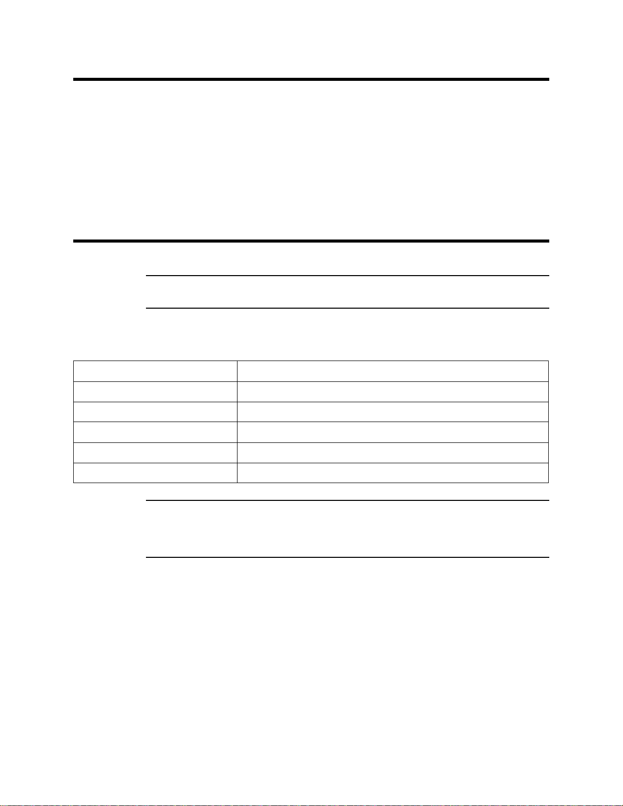
Specifications
WARNING: Do not use this product in a manner not specified in thi s instruction
Table 1 lists specifications for the combustible gas detector.
manual.
Table 1: 61-1000RK Specifications
Target Gas Combustible gas (Methane Calibration Standard)
Area Classification Explosionproof for Class I, Groups B, C, and D
Sampling Method Diffusion
Detection Range 0 to 100% LEL
Response Time 90% in 45 seconds
Accuracy ± 5% of reading or ± 2% LEL (whichever is greater)
W ARNING: When using the 61-1000RK, you must follow the instructions and warnings
in this manual to assure proper and safe operation of the 61-1000RK and to
minimize the risk of personal injury. Be sure to maintain and period ically
calibrate the 61-1000RK as described in this manual.
61-1000RK Co m bu st i bl e G a s D e te c to r • 1
Page 6

Description
J-Box
Rubber
Spacer,
3X
Red
Green
Black
Hydrogen Detector
White
This section describes the components of the 61-0140RK and 61-1000RK detectors. The
61-1000RK includes the 61-0140RK combustible gas detector and a junction box. A four
point terminal strip is provided inside the junction box for detector connections. The
61-0140RK does not include a junction box.
Figure 1: 61-1000RK Component Location
61-0140RK Combustible Gas Detector
The combustible gas detector is a catalytic type detector that produces an electrical output
that corresponds to the detection range. It is packaged in a 1/2 inch NPT nipple with a
sintered metal flame arrestor on one end allowing ambient air to diffuse into the detector.
The flame arrest or al so co ntai n s any s park s whi ch may occur within the detector. The 1/2
inch NPT mounting threads at the top of the detector allow you to mount it into the
bottom conduit hub of t he junction box. The controller conduit hubs are normally 3/4”
NPT, so a 3/4 in. x 1/2 in. NPT reducer may be necessary to install the combustible gas
detector. A rainshield screws onto the bottom of the detector (flame arrestor end). The
rainshield helps protect the detector from rain and debris in the monitoring environment.
Four color-coded leads extend from the top of the detector. The leads allow you to connect
the detector to the terminal block.
Junction Box
The junction box allows you to install the detector at a mounting site that is remote from a
controller, and it protects the detector wiring connections. Two conduit hubs allow you to
mount the detector to the junction box and connect the wiring from the detector to a
controller. Three spacers insta lled on the back of the junction box control the distance of
the junction box from a mounting surface and ensure that there is enough room to install a
calibration cup on the detector during calibration.
The bottom conduit hub includes a 3/4 in. x 1/2 in. reducer that allows you to screw the
2 • 61-1000RK Combustible Gas Detector
Page 7

Installation
J-Box
2.70 0.38
Combustible
Detector
3/4x1/2Reducing
Bus hing
.75
3/4 NPT
Female
3.65
7.50 max
Spacer, 3X
detector into the hub. The terminal block within the junction b ox facilita tes the wiring
process. A cover on the front of the junction box allows ac c ess to the interior of the
junction box.
This section describes procedures to mount the combustible gas detector in the
monitoring environment and wire the detector to a controller.
NOTE: The 61-0140RK detector retains its explosion proof classification only when
installed in the explosion proof junction box. The detecto r is not explosion proof
if installed in a controller conduit hub.
Mounting the Combustible Gas Detector
1. Select a mounting site that is representative of the monitoring environment. Consider
the following when you select the mounting site.
• Select a site where the detector is not likely to be bumped or disturbed. Ma ke sur e
there is sufficient room to perform start-up, maintenance, and calibration
procedures.
• Select a site where the target gas is likely to be found first. For lighter gases,
mount the detector near the ceiling; for heavier gases, mount the detector near the
floor.
Figure 2: Mounting the Combustible Ga s Detector
61-1000RK Co m bu st i bl e G a s D e te c to r • 3
Page 8

2. At the mounting site you select, hang or mount the junction box with the detector
facing down (see Figure 2).
Wiring the Combustible Gas Detector to a Controller
WARNING: Always verify that the power to the controller is off before you make
wiring connections.
1. Turn off the controlle r.
2. Turn off power to the controller.
3. If the detector is mounted remotely from a controller using the junction box, proceed
to step 4.
If the detector is mounted directly to a controller, it is normally factory wired. Confirm
that the detector’s wires are connected to the appropriat e contr oller det ector termin als
and skip to “S tart Up” on page 6. See F igu re 3, the c ontroller operat or’s manual, and
the controller’s detector head specification sheet for the 61-0140RK detector for the
wiring connection s.
4. Remove the junction box cover.
5. Guide a four-conductor, shielded cable or four wires in conduit through the unused
conduit hub of the junction box. Use appropriate conduit fittings and construction
technique for the environmental rating and hazardous location classification of the
junction box. The junction box is rated NEMA 4X and classified explosion proof for
Class I, Groups B, C, and D.
6. Connect the detector leads to the terminal block in the junction box.
CAUTION: Leave the shield drain wire insulated and disconnected at the detector. You will
connect the opposite end of the cabl e’s drain wire at the controller.
7. Secure the junction box cover to the junction box.
8. Route the cable or wires leading from the combustible gas detector through one of the
conduit hubs at the controller housing. Use appropriate conduit fittings and
construction technique for the environmental rating of the controller. RKI controllers
are typically rated NEMA 4X.
CAUTION: Do not route power and detector wiring through the same conduit hub. The power
cable may disru pt the transmission of the detect or signal to the controller.
9. Connect the wires to the applicable controller terminal strip. See the controller
operator’ s manual and the controller’s detector head specification sheet for the
61-1000RK detector.
10. If using shielded cable, connect the cable’s drain wire to an available chassis ground at
the controller. R KI controllers typically have a ground stud that is a convenient
grounding location.
4 • 61-1000RK Combustible Gas Detector
Page 9

Te rminal Strip
Black
White
J-Box
Combus tible
Detector
Controller LEL
Detector Terminals
GREEN
BLACK
RED
WHITE
Detector Wires
Green
Red
Figure 3: Wiring the Combustible Gas Detector to a Controller
61-1000RK Co m bu st i bl e G a s D e te c to r • 5
Page 10

Start Up
This section describes procedures to start up the combustible gas detector and place the
detector into normal operation.
Introducing Incoming Power
1. Complete the installation procedures described earlier in this manual.
2. Verify that the power wiring to the controller is correct and secure. Refer to the
controller operator’s manual.
3. Turn on power to the controller.
4. Turn on the controller.
5. Verify that the controller is on and op erating properly. Refer to the controller
operator’s ma nual.
CAUTION: Allow the detector to warm up for 5 minutes before you continue with the next
section, “Setting the Zero Reading”.
Setting the Zero Reading
WARNING: Do not remove the junction box cover while the circuits are energized
unless the area is determined to be non-hazardous. Keep the junction box
cover tightly closed during operation.
CAUTION: If you suspect the presence of combustible gas in the monit oring environment, use
the zero air calibration cylinder to introduce “fr e sh air” to the dete ctor and verify an
accurate zero reading.
1. Verify that the detector is in a fresh air environment (environment known to be free of
combustible gas and of normal oxygen concentration, 20.9%).
2. Verify a reading of 0% LEL at the controller.
If the display reading is 0% LEL, start up is complete. The combustible d e tector is in
normal operation. If the display reading is not 0% LEL, continue with step 3.
3. Perform a zeroing operation at the controller. See the contr oller operato r’s manual for
directions.
6 • 61-1000RK Combustible Gas Detector
Page 11

Maintenance
This section describes maintenance procedures. It includes preventive maintenance,
troubleshooting, and component replacement procedures.
Preventive Maintenance
This section describes a preventive maintenance schedule to ensure the optimum
performance of the combustible gas detector. It includes daily, monthly, and qua r terly
procedures.
Daily
Verify a display reading of 0% LEL at the controller. Investigate significant changes in the
reading.
Monthly
This procedure describes a test to verify that the combustible gas detector responds
properly to the target gas.
WARNING: The controller is not an active gas monitoring device during the response
test procedure.
NOTE: Performing a response te st on the combustible detector may cause alarms. Be
sure to put the controller into its calibration program or disable external alarms
before performing this test.
NOTE: The following procedure assumes the use of a calibration kit which includes a
calibration gas cylinder, a 0.5 LPM fixed flow regulator with an on/off knob, a
calibration cup for the detector, and a length of sample tubing.
Preparing for the response test
1. Place the controller into its calibration program or disable external alarms.
2. Verify that the controller display reading is 0% LEL.
If the controller reading is not 0% LEL, set the zero reading then continue this
procedure. See the controller operator’s manual for directions to set the zero reading.
3. Screw the regulator into the calibration cylinder.
4. Screw the calibration cup onto the bottom of the detector.
5. Use the calibration kit sample tubing to connect the regulator to the calibration cup.
Performing the response test
1. Turn the regulator’s on/off knob counterclockwise to open the regulator. Gas will
begin to flow.
2. Allow the gas to flow for one minute.
3. Verify that the reading is within ± 20% of the gas concentration.
61-1000RK Co m bu st i bl e G a s D e te c to r • 7
Page 12

NOTE: If the readings are not within ± 20% of the gas concentration, calibrate the
detector as described in the Calibration section of this manual.
4. Turn the regulator knob clockwise to close the regulator.
5. Unscrew the regulator from the calibration cylind er.
6. Unscrew the calibration cup from the detector.
7. When the display reading falls below the ala r m setpoints, return the controller to
normal operation.
8. Store the components of the calibration kit in a safe place.
Quarterly
Calibrate the detector as described in the Calibration section of this manual.
Troubleshooting
The troubleshooting guide describes symptoms, probable causes, and recommended
action for problems you may encounter with the combustible gas detector.
NOTE: This troubleshooting guide describes detector problems only. See the controller
operator’s manual for problems you may encounte r with the controller.
Table 2:Troubleshooting the Combustible Gas Detector
Condition Symptom(s) Probable Causes Recommended Action
Fail Condition • Controller indicates a
Slow or No
Response/
Difficult or
Unable to
Calibrate
fail condition.
• Detector responds
slowly or does not
respond to response
test.
• Unable to accurately
set the zero or
response reading
during calibration.
• Detector requires
frequent calibration.
Note: Under “normal”
circumstances, the
detector requires
calibration once every
three mont hs.
Some applications may
require a more freque nt
calibration schedule.
• The detector wiring is
disconnected or
misconnected.
• The detector zero
signal is low enough to
cause a fail condition.
• The detector is
malfunctioning.
• The calibration cylinder
is low, out-dated, or
defective.
• The calibration gas is
not an appr opriate
concentration.
• The detector is
malfunctioning.
1. Verify that the detector wiring is
correct and secure.
2. Calibrate the det ect or.
3. If the fail condition continues, replace
the detector.
4. If the fail condition continues, contact
RKI for further instruction.
1. Verify that the calibration cylinder
contains an adequate supply of a
fresh test sample.
2. Verify that the calibration gas
concentration is appropriate for the
detector.
3. If the calibration/response difficulties
continue, replace the detector.
4. If the calibration/response difficulties
continue, contact RKI for further
instruction.
8 • 61-1000RK Combustible Gas Detector
Page 13

Replacing the Combustible Detector
1. Turn off the controlle r.
2. Turn off power to the controller.
3. If the detector is installed directly on a controller, open the controller door.
If the detector is installed remotely from a controller in a junction box, remove the
junction box cove r.
4. If the detector is installed directly on a controller, disconnect the detector leads from
the detector terminal strip in the controller. Note the position of the color-coded leads
as you remove them.
If the detector is installed remotely from a controller in a junction box, disconnect the
detector leads from the terminal block in the junction box. Note the position of the
color-coded leads as you remove them.
5. Unscrew the detector from the controller conduit hub or junction box conduit hub.
6. Guide the detector leads of the replacement detector through the controller conduit
hub or junction box conduit hub, then screw the mounting threads of the detector into
the hub. If necessary for environmental conditions, apply thread sealant or teflon tape
to the hub and/or detector threads to seal them.
7. If the detector is installed directly on a controller, connect the detector leads to the
appropriate detector terminal strip terminals. See Figure 3 for wiring to a generic
controller. See the controller operator’s manual and the controller ’s detector head
specification sheet for the 61-0140RK detector for wiring specific to your controller.
If the detector is installed remotely from a controller in a junction box, connect the
detector leads to the terminal block the same way the old detector was wired (see
Figure 3). See the controller operator’ s manual and the controller’s detector head
specification sheet for the 61-1000RK detector to verify the connections to the
controller are correct.
8. If the detector is installed remotely from a controller in a junction box, reinstall the
junction box cove r.
9. Turn on or plug in power to the controller.
10. Turn on the controller and place into normal operation.
CAUTION: Allow the replacement detector to warm up for 5 minutes before you continue with
the next step.
11. Calibrate the replacement detector as described in the Calibration section of this
manual.
Calibration Frequency
Although there is no particular calibration frequency that is correct for all applications, a
calibration frequency of every 3 to 6 months is adequate for most combustible gas detector
applications. Unless experience in a particular application dictates otherwise, RKI
Instruments, Inc. recommends a calibration frequency of every 3 months.
If an application is not very demanding, for example detection in a clean, temperature
controlled environment where combustible gas is not normally present and calibration
adjustments are minimal at calibration, then a calibration frequency of every 6 months is
61-1000RK Co m bu st i bl e G a s D e te c to r • 9
Page 14

Calibration
adequate.
If an application is very demanding, for example if combustible gas is present often and in
significant concentrations or the environment is not well controlled, then more frequent
calibration than e v ery 3 mo nt h s m ay be n e ces s ary. If potential catalyst poisons are known
or likely to be present, more frequent ca libration than every 3 months will be necessary.
This section describes how to calibrate the combustible gas detector. It includes
procedures to prepare for calibration, set the zero reading, set the response reading, and
return to normal operation.
W ARNING: The controller is not an active gas monitoring device during the calibration
procedure.
NOTE: The following procedure assumes the use of a calibration kit which includes a
calibration gas cylinder, a 0.5 LPM fixed flow regulator with an on/off knob, a
calibration cup for the detector, and a short piece of sample tubing to connect the
regulator to the calibration cup.
Prepari ng for Ca libration
1. Screw the calibration cup onto the bottom of the detector.
2. Screw the regulator into the calibration cylinder.
3. Use the calibration kit sample tubing to connect the regulator to the calibration cup.
4. Place the controller into its calibration program or disable external alarms.
NOTE: Calibrating the combustible detector may cause alarms. Be sure to put the
controller into its calibration program or disable external alarms before
continuing.
Setting the Zero Reading
CAUTION: If you suspect the mon itoring environment is not free of co mbustible vapors, use the
calibration kit and a zero air calibration cylinder to introduce “fresh air” to the
detector and verify an accurate zero setting.
1. Verify that the detector is in a fresh air environment.
2. Follow the directions in the controller’s operator’s manual for setting the zero
reading.
Setting the Response Reading
1. Follow the directions in the controller’s operator’s manual for setting the response
reading (span).
2. When the directions call for exposing the detector to gas, turn the regulator’s on/off
knob counterclockwise to open it.
3. Allow the gas to flow for one minute before continuing with the directions.
10 • 61-1000RK Combustible Gas Detector
Page 15

4. After setting the response reading, turn the regulator’s on/off knob clockwise to close
it.
5. Unscrew the regulator from the cylinder.
Returning to Normal Operation
1. Unscrew the calibration cup from the detector.
NOTE: For convenience, leave regulator and calibration cup connected by the sample
tubing.
2. When the controller display reading falls below the alarm points, return the controller
to normal o peration.
NOTE: If you do not allow the gas reading to decrease below the alarm points, then
unwanted alarms may occur.
3. Verify that the controller display reading decreases and stabilizes at 0 %LEL.
4. Store the components of the calibration kit in a safe and convenient place.
Parts List
Table 3 lists replacement parts and accessories for the 61-1000RK combustible gas detector.
Table 3: Parts List
Part Number Description
18-0400RK-01 Junction box with spacers
61-0140RK Replacement combustible gas detector
71-0067RK 61-1000RK Combus tible Gas Detector Operator’s Manual (this document)
81-0007RK-01 Calibration cylinder (15% LEL Hexane in air, 34 liter)
81-0012RK-01 Calibration cylinder (50% LEL Methane in air, 34 liter)
81-0076RK-01 Zero air calibration cylinder (34 liter)
81-1003RK Regulator, 0.5 liter/minute; continuous flow (for 17 and 34 liter calibra tion cylinders)
81-1117RK Calibration c up
61-1000RK Combustible Gas Detector • 11
 Loading...