

Page 1

49-8104RK
Standby Battery
Operator’s Manual
Part Number: 71-0118RK
Revision: B
Released: 2/19/13
www.rkiinstruments.com
Page 2

Product Warranty
RKI Instruments, Inc. warrants gas alarm equipment sold by us to be free from defects in
materials, workmanship, and performance for a period of one year fr o m date of shipment
from RKI Instruments, Inc. Any parts found defective withi n tha t period will be repaired
or replaced, at our option, free of charge. This warranty does not apply to those items
which by their nature are subject to deterioration or consumption in normal ser v ice, and
which must be cleaned, repaired, or replaced on a routine basis. Examples of such items
are:
W arranty is voided by abuse including mechanical damage, alteration, rough handling, or
repair procedures not in accordance with the operator’s manual. This warranty indicates
the full extent of our liability , a nd we are not r esponsible for removal or r eplacement costs,
local repair costs, transportation costs, or contingent expenses incurred without our prior
approval.
a) Absorbent cartridges d) Batteries
b) Pump diaphragms and valves e) Filter elements
c) Fuses
THIS WARRANTY IS EXPRESSLY IN LIEU OF ANY AND ALL OTHER
WARRANTIES AND REPRESENTATIONS, EXPRESSED OR IMPLIED,
AND ALL OTHER OBLIGATIONS OR LIABILITIES ON THE PART OF
RKI INSTRUMENTS, INC., INCLUDING BUT NOT LIMITED TO, THE
WARRANTY OF MERCHANTABILITY OR FITNESS FOR A
PARTICULAR PURPOSE. IN NO EVENT SHALL RKI INSTRUMENTS,
INC. BE LIABLE FOR INDIRECT, INCIDENTAL, OR CONSEQUENTIAL
LOSS OR DAMAGE OF ANY KIND CONNECTED WITH THE USE OF
ITS PRODUCTS OR FAILURE OF ITS PRODUCTS TO FUNCTION OR
OPERATE PROPERLY.
This warranty covers instruments and parts sold to users by authorized distributors,
dealers, and representatives as appointed by RKI Instruments, Inc.
We do not as su m e i ndemnification for any accident or damage caused b y t he op e ration of
this gas monitor, and our warranty is limited to the replacement of parts or our complete
goods.
2 • 49-8104RK Standby Batter y
Page 3
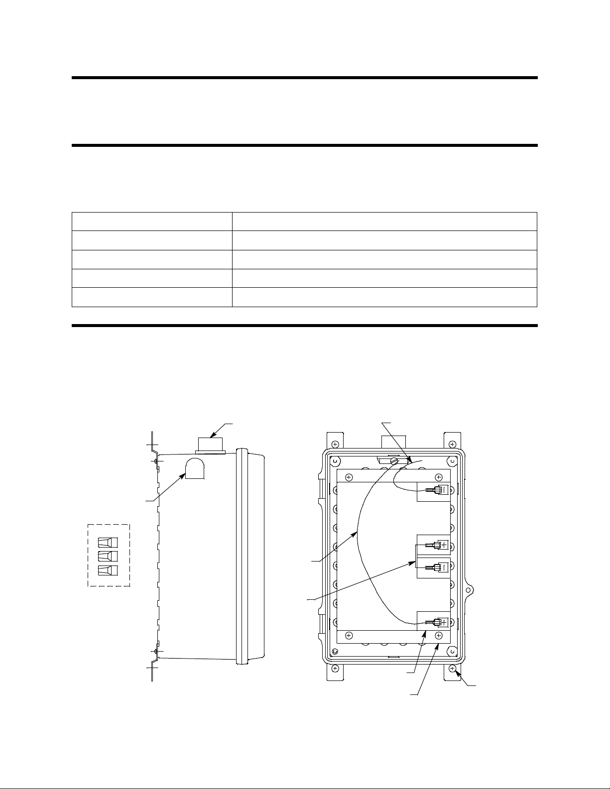
Overview
Note: Front
View Shown
Without Door
Wire (black) for negative c onnection
4X 1/4"
Screws
3/4" NPT
Conduit Hub
12 Am p Hour
Battery, 2X
Vent
User
Installed
Jumper
Wire nuts, 3
shipped with unit
(1 extra)
Wire (red)
for po sitive
connection
Battery Mounting Bracket
This manual describes the 49-8104RK standby battery. This manual also describes how to
install and maintain the stan d b y battery.
Specifications
Table 1 lists specifications for th e standby battery.
Table 1: Specifications
Construction (housing) Weatherproof ABS plastic
Power Rating 24 VDC, 12 AH (amp hour)
Operating Temperature 32° F to 104° F (0°C to 40°C)
Size 11.28” H x 7.48” W x 5.91” D (287 mm D x 190 mm W x 150 mm D)
Weight 22 lbs (10 kg)
Description
The 49-8104RK Standby Battery is designed for use with a gas monitoring controller
capable of running from 24 VDC such as the RKI Instruments, Inc. Beacon 200, Beacon
410, or Beacon 800 controller. It can provide temporary power to a controller if primary
AC power is lost. The standby battery consists of the ho using, two batteries (shipped
uninstalled), three connection wires (shipped in a small bag), and wire nuts for wiring
connections. The figure below shows the batteries and wires installed.
Figure 1: Standby Battery Component Location
49-8104RK Standby Battery • 3
Page 4

Housing
The standby battery’s fiberglass housing is weather- and corrosion-resistant. It is suitable
for installation where general purpose equipment is in use. The housing door is hinged on
the left side and is secured by two latches on the right side. Four mounting feet are
attached to the back of the housing (one at each corner). The mounting feet allow you to
install the housing to a vertical surface. A cond uit hub on the top of the housing is for
external wiring connections. A weathe r-resistant vent on the upper left side prevents
buildup of hydrogen in the housing if it is vented by the batteries.
Batteries
Two lead acid 12 VDC, 12 AH batteries are shipped with the housing but are not installed.
The batteries must be installed into the housing and connected with a wire jumper s o th at
they produce 24 VDC. T wo wires must be connected to the batteries to allow connection to
the positive and negative of the standby battery. The ends of these wires are covered with
insulating shrink tubing to prevent shorting during shipment. These pi eces of shrink
tubing will have to be removed during installation of the standby battery (see “Wiring the
Standby Battery to a Controller” on page 7 ).
Wire Nuts
Three wire nuts are provided with the standby battery for wiring connections. The wire
nuts are shipped in the standby battery packaged in a small plastic bag. Only two wiring
connections will have to be made to the standby battery (see “Wiring the Standby Battery
to a Controller” on page 7), so one of the wire nuts is provided as an extra in case one is
lost or damaged.
4 • 49-8104RK Standby Batter y
Page 5

Installation
Battery
Mounting
Bracket
Note: Front
View Shown
Without Door
Jumper Wire
12 Amp Hour
Battery, 2X
Wire (red)
for positive
connection
Wire (black) for
negative
connection
Wire nuts, 3
shipped with unit
(1 extra )
This section describes procedures to mount the standby battery and wire it to a controller.
Installing the Batteries
The batteries are shipped separately in order to prevent damage to the housing. Three
wires are provided in a bag in order to make connections to the batteries. The figure below
shows how the standby battery is shipped.
Figure 2: Standby Battery Components as Shipped
1. Place the enclosure on a table or bench top and open the door.
2. Unscrew the four screws retaining the battery mounting bracket to the case.
3. Carefully remove the battery mounting bracket from the case.
4. Place the batteries in the enclosure and arrange them so that all battery terminals are
on the right as shown in Figure 1 .
5. Place the battery bracket over the batteries and line up the mounting holes in the
bracket with the mounting holes in the case.
6. Install the four screws that retain the battery bracket and tighten firmly.
7. Install the positive (red) wire to the “+” connection on the bottom battery (see
Figure 1). This wire is one of three wires in a small bag included with the shipping
contents.
8. Install the negative (black) wire to the “-” connection of the top battery (see Figure 1).
This wire is one of three wires in a small bag included with the shipping co ntents.
49-8104RK Standby Battery • 5
Page 6

CAUTION: Before continuing, confirm that the positive wire (red) and the negative wire (black)
3.74
7.48
3/4" Conduit
Hub
6.15
3.07
5.91
11.88 Max
1/4" Screw, 4X,
User Supplied
13.00
11.28
11.38 Min
are not shorting to each other. Each wire has s hrink tubing on the end to prevent
shorting. Leave the shrink tubing on.
9. Install the wire jumper between the “+” connection of the top battery and the “-”
connection of the bottom battery (see Figure 1). This wire is one of three wires in a
small bag included with the shipping contents.
Mounting the Standby Battery
1. Select a mounting site close to the controller that requires standby power. Consider
the following when you select the mounting site.
• Select a site where the standby battery is not likely to be bumped or disturbed.
Make sure there is sufficient room to perform maintenance procedures.
• The conduit hub on the top of the standby battery housing makes wiring to a
controller convenient if the standby battery is mounted below a con troller.
2. Open the standby battery door and remove any packin g materials from the housing.
Be careful not to lose the three wire nuts that are provided for wiring connections.
3. Close and latch the standby battery housing door.
4. The standby battery is shipped with the mounting feet positi oned be hind the hou sing.
Loosen the screws that secure the feet to the housing, rotate the feet to their mounting
position as shown in Figure 3, th en tighten the screws.
Figure 3: Outline & Mounting Dimensions
5. Insert 1/4 inch screws through the slots in the mounting feet at each corner of the
housing to secure the housing to the mounting surface.
6 • 49-8104RK Standby Batter y
Page 7

Wiring the Standby Battery to a Controller
WARNING: Always verify that all power to the controller is OFF before you make
wiring connections.
1. Turn off the cont roller.
2. Turn off or unpl ug power to the controller.
3. Install an appropriately rat ed cable bushing or conduit to the conduit hub on the
controller that will be used for wires from the standby battery.
4. Open the standby battery housing door.
5. Install an appropriately rat ed cable bushing or conduit to the conduit hub on the
standby battery housing.
6. Route two wires in conduit or a two wire cable with wires from the controller conduit
hub to the standby battery conduit hub. 16 AWG wire is recommended, but the wire
nuts will accommodate wire up to 14 AWG wire.
7. Connect the two wires to the 24 VDC power input terminals at the controller. Note
which wire is positive and which wi re is nega tive.
8. A short factory installed jump er wire terminated with push-on lugs connects the two
batteries in the standby battery. Remove this wire from one of the battery terminals
and make sure it is not contacting the terminal.
9. When the standby battery is shipped from the factory, the ends of the two wires
provided for external wiring connections are covered with shrink tubing to prevent
shorting of the batteries during shipment. Remove the shrink tubing and strip the end
of each wire. Take care not to short the wires to the mounting bracket or to each other.
49-8104RK Standby Battery • 7
Page 8

10. Use the wire nuts provided with the standby battery to connect the positive and
Connections
Made With Wire
Nuts Provided
RESET
CH1
OUT
CH2
OUT
+
+
BAT
BUZ +
BAT +
Contr oll er Terminal Strip
Beacon 200 Housing
User
Installed
Jumper
Standby Battery Shown Without Door
RESET
BUZ
negative wires in the standby battery to the positive and negative wires coming from
the controller as shown in Figure 4, Figure 5, and Figure 6.
Figure 4: Wiring the Standby Battery to a Beacon 200
8 • 49-8104RK Standby Batter y
Page 9

Connections
Made With Wire
Nuts Prov ided
Controll er Ter minal Str ip
Beacon 410 Housing
User
Installed
Jumper
Standby Battery Shown Without Door
Figure 5: Wiring the Standby Battery to a Beacon 410
49-8104RK Standby Battery • 9
Page 10

Connections
Made With Wire
Nuts Pro vi ded
NC
NO
BAT+
ALM2
NO
C
C
NO
NC
RX
GND
+28V
TX
RESET
BUZ +
BUZ
RESET
BAT
FAIL ALM1
Beacon 800 Housing
User
Installed
Jumper
Cont rol ler Te rminal Str ip
24
VDC
Standby Battery Shown Without Door
C
NC
10 • 49-8104RK Standby Bat tery
Figure 6: Wiring the Standby Battery to a Beacon 800
11. Turn on power to the controller.
12. Turn on the controller.
13. When the controller has completed its startup sequence, re-connect the end of the
jumper wire to the battery terminal from which it was removed.
14. Close the standby battery ho using door.
15. The on/off switch in the Beacon 200, Beacon 410, and Beacon 800 controls AC power
to the instruments. Verify that the standby battery is installed properly by flipping the
on/off switch to the off position and observing that the controller continues to operate
powered by the standby battery.
16. Flip the controller power switch to the on position.
Page 11

Operation
When the standby battery is connected to an RKI Instruments, Inc. controller such as the
Beacon 200, Beacon 410 , o r th e Beacon 800, the controller m ai n tain s a t rick l e ch arge on the
battery to keep it fully charged. If primary AC power to the controller goes down, the
standby battery will power the controller for a limited amount of time until primary
power returns. When primary AC power returns, the controller will begin charging the
standby battery. Recharge time will vary depending on the controller and the level of
discharge, but a typical recharge time if the battery is completely discharged is about 4
days.
Runtime will vary depending on the con troller and config uration of the controller. The
table below shows typical controller runtimes for common configu rations.
Table 2: Typical Controller Runtimes on Standby Battery
Controller Controller Detector Configuration Runtime
Beacon 200 2 Channels LEL 40 hours
Beacon 200 2 Channels Toxic or Oxygen 90 hours
Beacon 200 2 Channels 35-3000RK Sample Draw 18 hours
Beacon 200 2 Channels GD-K7D2 Sampl e Draw 22 hours
Beacon 410 4 Channels LEL 40 hours
Beacon 410 4 Channels Toxic or Oxygen 96 hours
Beacon 410 4 Channels 35-3000RK Sample Draw 14 hours
Beacon 410 4 Channels GD-K7D2 Sampl e Draw 17 hours
Beacon 800 8 Channels LEL 18 hours
Beacon 800 8 Channels Toxic or Oxygen 60 hours
Beacon 800 8 Channels 35-3000RK Sample Draw 4 hours
Beacon 800 8 Channels GD-K7D2 Sample Draw 5 hours
49-8104RK Standby Battery • 11
Page 12

Maintenance
This section describes preventive maintenance and troubleshooting procedures. It also
includes component replacement procedures and a parts list.
Preventive Maintenance
Check the standby battery voltage with a volt meter on a quarterly basis and verify that it
is fully charged. A fully charged standby battery connected to a controller that trickle
charges it will typically measure between 28 volts and 29 volts.
Troubleshooting
The troubleshooting guide describes symptoms, probable causes, and recommended
action for problems you may encounter with the standby battery.
Condition Symptom(s) Probable Causes Recommended Action
Low Battery
Voltage
•The standby battery
voltage measures
below 28VDC at t he
quarterly voltage
check.
• The wiring to the
controller is
disconnected or
misconnected.
•The wire nut
connections in the
standby battery are
not properly made.
• The wiring to the
battery terminals in
the standby battery is
disconnected.
• The controller is not
fully charging the
standby battery.
1. Verify that the wiring at the
controller is correct and secure.
2. Verify that the wire nut connections
in the standby battery are properly
made.
3. Verify that th e lugs that fit over the
battery terminals are securely and
correctly installed.
4. Check the DC fuse at the controller.
5. If the low voltage condition
continues, contact RKI for furth e r
instruction.
Replacing a Battery
If one of the 12 VDC batteries in the standby battery needs replacement, RKI Instruments,
Inc. recommends that both batteries be replaced. The part number for a replacement
battery is listed in the parts list at the end of this section. Follow the instructions below to
replace the batteries.
1. Turn off the cont roller.
2. Turn off power to the controller.
3. Open the standby battery housing door.
4. Remove the jumper wire that connects the two batteries. It connects to both batteries
with a push-on lug.
5. Remove the remaining two connections to the batteries, the positive and negative
connections, by removing the push-on lugs from each battery.
6. Fix the positive and negative wires out of the way.
7. Unscrew the top two screws retaining the battery bracket to the case. Hold the battery
bracket in place so that the batteries do not fall out of the case.
8. While holding the battery bracket in place, unscrew the bottom two screws retaining
the battery bracket in place. Be careful when the screws are removed as the batteries
are heavy and may fall out of the housing if the battery bracket is not held firmly
when the screws are removed.
12 • 49-8104RK Standby Bat tery
Page 13

9. Carefully remove the battery bracket and batteries from the case.
10. Replace the batteries in the bracket with the new batteries.
NOTE: Dispose of the old batteries properly.
11. Place the battery bracket with the batteries in the case and line up the mounting holes
in the bracket with the mounting holes in the case. Hold the bracket with the batteries
in place firmly.
12. Install the bottom screws that retain the battery bracket and tighten firmly.
13. Install the top screws that retain the battery bracket and tighten firmly.
14. Install the positive and negative connections to the appropriate battery terminals (see
Figure 4, Figure 6, and Figure 6).
15. Turn on power to the controller.
16. Turn on the controller.
17. When the controller has completed its warm-up sequence, install the jumper wire
between the two batteries (see Figure 4, Figure 6, and Figure 6).
18. Close the standby battery ho using door.
19. The on/off switch in the Beacon 200, Beacon 410, and Beacon 800 controls AC power
to the instruments. Verify that the standby battery is installed properly by flipping the
on/off switch to the off position and observing that the controller continues to operate
powered by the standby battery.
20. Flip the on/off switc h to the on position.
Parts List
Table 3 below list s sp are parts for the stan d b y b at tery.
Table 3: Standby Battery Spare Parts
Part Number Description
18-0107RK 3/4” NPT conduit hub
18-0112RK Vent
45-0600RK Wire nut, for 22 - 14 AWG wire
49-1552RK Battery , le ad acid, 12 V, 12 amp hour
49-8104RK Standby Battery • 13
 Loading...