

Page 1

35-3010RK-02 Sample-Draw
Part Number: 71-0208RK
Revision: C
Released: 9/24/13
Detector
www.rkiinstruments.com
Page 2

WARNING
Read and understand this instruction manual before operating
detector . Improper use of the dete ctor could result in bodily harm
or death.
Periodic calibration and maintenance of the detector is essential
for proper operation and correct readings. Please calibrate and
maintain this detector regularly! Frequency of calibration
depends upon the type of use you have and the sensor types.
T ypical calibration frequencies for most applications a re between
3 and 6 months, but can be required more often or less often
based on your usage.
35-3010RK-02 Sample-Draw Detector
Page 3

Product Warranty
RKI Instruments, Inc. warrants gas alarm equipment sold by us to be free fro m defects in
materials, workmanship, and performance for a period of one year fr o m date of shipment
from RKI Instruments, Inc. Any parts found defective withi n tha t period will be repaired
or replaced, at our option, free of charge. This warranty does not apply to those items
which by their nature are subject to deterioration or consumption in normal ser v ice, and
which must be cleaned, repaired, or replaced on a routine basis. Examples of such items
are:
W arranty is voided by abuse including mechanical damage, alteration, rough handling, or
repair procedures not in accordance with the operator’s manual. This warranty indicates
the full extent of our liability , a nd we are not r esponsible for removal or r eplacement costs,
local repair costs, transportation costs, or contingent expenses incurred without our prior
approval.
a) Absorbent cartridges d) Batteries
b) Pump diaphragms and valves e) Filter elements
c) Fuses
THIS WARRANTY IS EXPRESSLY IN LIEU OF ANY AND ALL OTHER
WARRANTIES AND REPRESENTATIONS, EXPRESSED OR IMPLIED,
AND ALL OTHER OBLIGATIONS OR LIABILITIES ON THE PART OF
RKI INSTRUMENTS, INC. INCLUDING BUT NOT LIMITED TO, THE
WARRANTY OF MERCHANTABILITY OR FITNESS FOR A
PARTICULAR PURPOSE. IN NO EVENT SHALL RKI INSTRUMENTS,
INC. BE LIABLE FOR INDIRECT, INCIDENTAL, OR CONSEQUENTIAL
LOSS OR DAMAGE OF ANY KIND CONNECTED WITH THE USE OF
ITS PRODUCTS OR FAILURE OF ITS PRODUCTS TO FUNCTION OR
OPERATE PROPERLY.
This warranty covers instruments and parts sold to users by authorized distributors,
dealers, and representatives as appointed by RKI Instruments, Inc.
We do not assume indemnification fo r any accident or dama g e ca u s e d by the operation of
this gas monitor, and our warranty is limited to the replacement of parts or our complete
goods.
35-3010RK-02 Sample-Draw Detector
Page 4

Table of Contents
Overview . . . . . . . . . . . . . . . . . . . . . . . . . . . . . . . . . . . . . . . . . . . . . . . . . . . . . . . . . . . . . . . . . . . 1
Specifications. . . . . . . . . . . . . . . . . . . . . . . . . . . . . . . . . . . . . . . . . . . . . . . . . . . . . . . . . . . . . . . . 1
Description. . . . . . . . . . . . . . . . . . . . . . . . . . . . . . . . . . . . . . . . . . . . . . . . . . . . . . . . . . . . . . . . . . 2
Housing . . . . . . . . . . . . . . . . . . . . . . . . . . . . . . . . . . . . . . . . . . . . . . . . . . . . . . . . . . . . . . . . . . . . . . . . . . . . . 2
Flow System. . . . . . . . . . . . . . . . . . . . . . . . . . . . . . . . . . . . . . . . . . . . . . . . . . . . . . . . . . . . . . . . . . . . . . . . . . 3
Detection System. . . . . . . . . . . . . . . . . . . . . . . . . . . . . . . . . . . . . . . . . . . . . . . . . . . . . . . . . . . . . . . . . . . . . . 5
Installation . . . . . . . . . . . . . . . . . . . . . . . . . . . . . . . . . . . . . . . . . . . . . . . . . . . . . . . . . . . . . . . . . . 8
Mounting the Sample-Draw Detector . . . . . . . . . . . . . . . . . . . . . . . . . . . . . . . . . . . . . . . . . . . . . . . . . . . . 8
Connecting the Sample Lines to the Sample-Draw Detector. . . . . . . . . . . . . . . . . . . . . . . . . . . . . . . . . 9
Wiring the Sample-Draw Detector to a Controller . . . . . . . . . . . . . . . . . . . . . . . . . . . . . . . . . . . . . . . . . 9
Start Up. . . . . . . . . . . . . . . . . . . . . . . . . . . . . . . . . . . . . . . . . . . . . . . . . . . . . . . . . . . . . . . . . . . . 12
Introducing Incoming Power . . . . . . . . . . . . . . . . . . . . . . . . . . . . . . . . . . . . . . . . . . . . . . . . . . . . . . . . . . 12
Setting the Zero Reading. . . . . . . . . . . . . . . . . . . . . . . . . . . . . . . . . . . . . . . . . . . . . . . . . . . . . . . . . . . . . . 12
Operation . . . . . . . . . . . . . . . . . . . . . . . . . . . . . . . . . . . . . . . . . . . . . . . . . . . . . . . . . . . . . . . . . . 13
Normal Operation . . . . . . . . . . . . . . . . . . . . . . . . . . . . . . . . . . . . . . . . . . . . . . . . . . . . . . . . . . . . . . . . . . . 13
Low Flow Alarm. . . . . . . . . . . . . . . . . . . . . . . . . . . . . . . . . . . . . . . . . . . . . . . . . . . . . . . . . . . . . . . . . . . . . 13
Maintenance. . . . . . . . . . . . . . . . . . . . . . . . . . . . . . . . . . . . . . . . . . . . . . . . . . . . . . . . . . . . . . . . 13
Preventive Maintenance . . . . . . . . . . . . . . . . . . . . . . . . . . . . . . . . . . . . . . . . . . . . . . . . . . . . . . . . . . . . . . 13
Troubleshooting . . . . . . . . . . . . . . . . . . . . . . . . . . . . . . . . . . . . . . . . . . . . . . . . . . . . . . . . . . . . . . . . . . . . . 14
Replacing Components of the Sample-Draw Detector. . . . . . . . . . . . . . . . . . . . . . . . . . . . . . . . . . . . . 16
Adjusting the Low Flow Setting. . . . . . . . . . . . . . . . . . . . . . . . . . . . . . . . . . . . . . . . . . . . . . . . . . . . . . . . 17
Calibration Frequency . . . . . . . . . . . . . . . . . . . . . . . . . . . . . . . . . . . . . . . . . . . . . . . . . . . . . . . 18
Calibration, LEL Detector . . . . . . . . . . . . . . . . . . . . . . . . . . . . . . . . . . . . . . . . . . . . . . . . . . . . 18
Setting the Zero Reading. . . . . . . . . . . . . . . . . . . . . . . . . . . . . . . . . . . . . . . . . . . . . . . . . . . . . . . . . . . . . . 18
Setting the Response Reading. . . . . . . . . . . . . . . . . . . . . . . . . . . . . . . . . . . . . . . . . . . . . . . . . . . . . . . . . . 18
Returning to Normal Operation. . . . . . . . . . . . . . . . . . . . . . . . . . . . . . . . . . . . . . . . . . . . . . . . . . . . . . . . 19
Calibration, Oxygen Detector. . . . . . . . . . . . . . . . . . . . . . . . . . . . . . . . . . . . . . . . . . . . . . . . . 19
Setting the Zero Reading. . . . . . . . . . . . . . . . . . . . . . . . . . . . . . . . . . . . . . . . . . . . . . . . . . . . . . . . . . . . . . 20
Setting the Fresh Air Reading. . . . . . . . . . . . . . . . . . . . . . . . . . . . . . . . . . . . . . . . . . . . . . . . . . . . . . . . . . 20
Returning to Normal Operation. . . . . . . . . . . . . . . . . . . . . . . . . . . . . . . . . . . . . . . . . . . . . . . . . . . . . . . . 20
Calibration, H2S Detector . . . . . . . . . . . . . . . . . . . . . . . . . . . . . . . . . . . . . . . . . . . . . . . . . . . . 20
Preparing for Calibration. . . . . . . . . . . . . . . . . . . . . . . . . . . . . . . . . . . . . . . . . . . . . . . . . . . . . . . . . . . . . . 20
Setting the Zero Reading. . . . . . . . . . . . . . . . . . . . . . . . . . . . . . . . . . . . . . . . . . . . . . . . . . . . . . . . . . . . . . 21
Setting the Response Reading. . . . . . . . . . . . . . . . . . . . . . . . . . . . . . . . . . . . . . . . . . . . . . . . . . . . . . . . . . 21
Returning to Normal Operation. . . . . . . . . . . . . . . . . . . . . . . . . . . . . . . . . . . . . . . . . . . . . . . . . . . . . . . . 21
Parts List . . . . . . . . . . . . . . . . . . . . . . . . . . . . . . . . . . . . . . . . . . . . . . . . . . . . . . . . . . . . . . . . . . . 22
35-3010RK-02 Sample-Draw Detector
Page 5

Overview
This manual describes the 35-3010RK-02 sample draw detector. This manual also
describes how to install, start up, maintain, and calib rate the sample draw detector wh en
it is used with a gas monitoring controller. A parts list at the end of this manual lists
replacement parts and accessories for the detector.
Specifications
Table 1 lists specifications for the 35-3010RK-02.
Target Gases & Detection Ranges Combustible Gas: 0 - 100% LEL
Input Power 24 VDC
Current Draw 200 mA
Table 1: Specifications
Oxygen: 0-25% volume
Hydrogen Sulfide (H
S): 0 - 100 ppm
2
Construction (housing) Fiberglass/polyester (NEMA 4X)
Dimensions 15.44 in. H x 12.55 in. W x 8.31 in. D
Weight 14 lbs.
Sampling Method Sample draw
Sample Flow 1.2 SCFH (nominal)
Response Time 90% in 30 seconds
Accuracy Combustible Gas
± 5% of reading or ± 2% LEL (whichever is greater)
Oxygen
± 0.5% O
Hydrogen Sulfide:
± 5% of reading or ± 2 ppm H
WARNING: When using the 35-3010RK-02, you must follow the instructions and
warnings in this manual to assure proper and safe opera tion of the
35-3010RK-02 and to minimize the risk of personal injury. Be sure to
maintain and periodically calibrate the 35-3010RK-02 as described in this
manual.
:
2
:
S (whichever is greater)
2
35-3010RK-02 Sample-Draw Detector • 1
Page 6
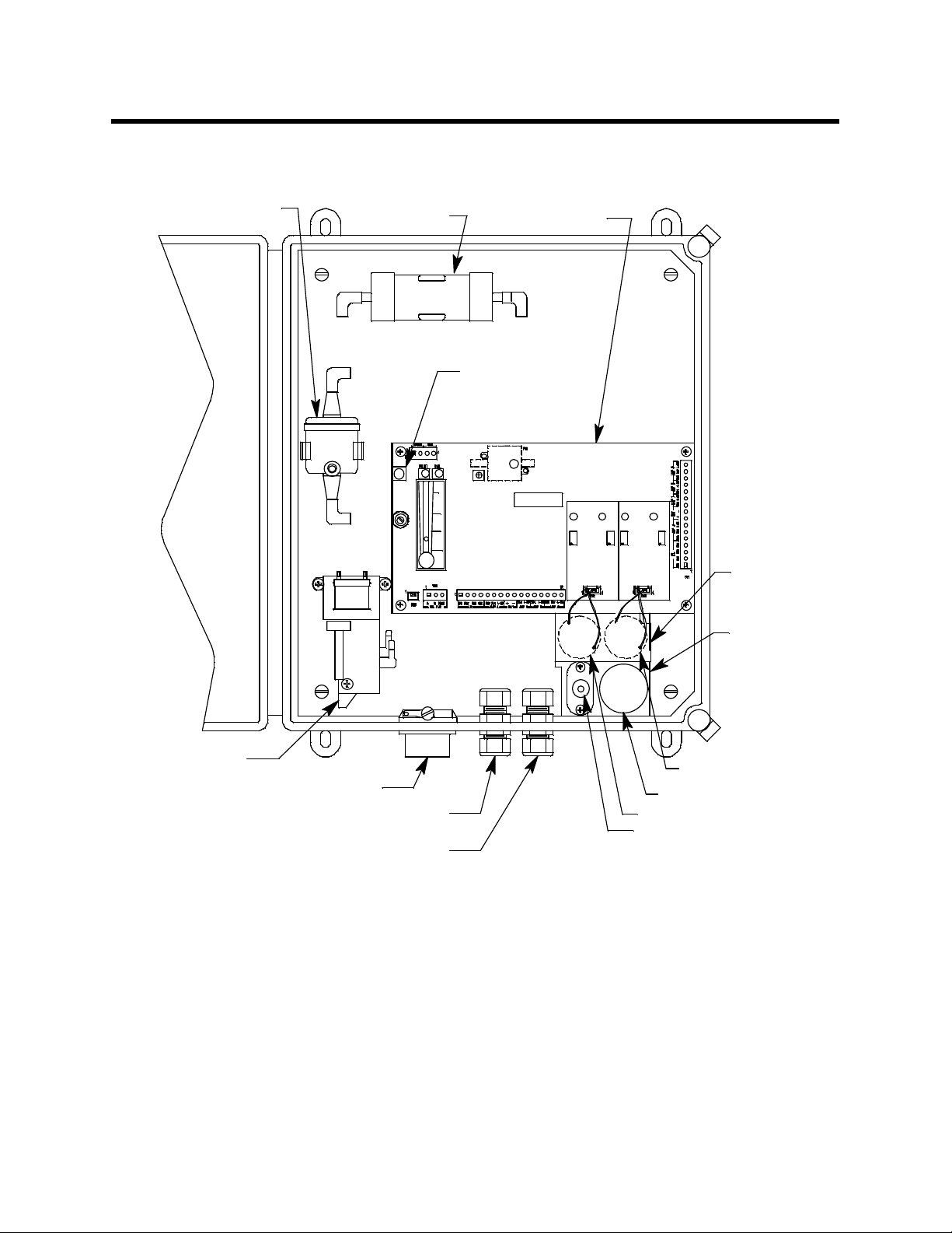
Description
Hydrophobic
Filter (AcroPak)
This section describes the components of the 35-3010RK-02 sample draw detector. The sample
draw detector consists of the housing, flow system, and detection system.
Charcoal Fil ter
Main Circuit Board
Reset Switch
Amp 1
Pump
3/4 Conduit Hub, 2X
Exhaust Fit t ing For 1/4"
OD R igi d Tubing
Inlet FittingFor 1/4"
OD Rigid Tubing
Figure 1: Sample Draw Detector Compo n en t Location
Amp 2
H2S Sen sor
Oxygen Sensor
CO Senso r
Combustible
Sensor
Preamp
Circuit
Board
Flow
Block
Housing
The sample draw detector’s fiberglass housing is weather- and corrosion-resistant. It is
suitable for installation where general purpose equipment is in use. The housing door is
hinged on the left side and is secured by two latches on the right side.
Four mounting feet are attached to the back of the housing (one at each corner). Use the
mounting feet to install the housing to a vertical surface. Use the two conduit hubs on the
bottom of the housing to make wiring connections.
An aluminum subpanel is mounted to th e interior of the housing. The sample draw
detector’s internal components are mounted to the subpanel.
2 • 35-3010RK-02 Sample-Draw Detector
Page 7
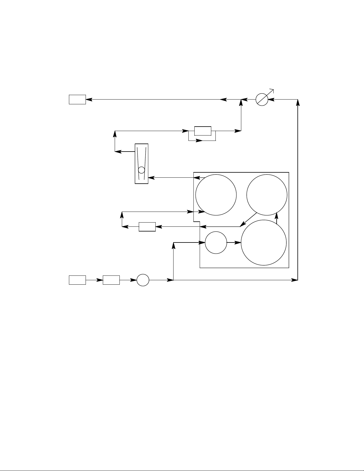
Flow System
The sample draw detector ’s flo w system consists of the INLET fitting, hydrophobic filter,
charcoal filter, pump, flowmeter, bypass valve, status lights, pressure switch, flow block,
and EXHAUST fitting (see Figure 1). Figure 2 illustrates how the gas sample moves
through the flow system.
Bypass
Valve
Exhaust
Pressure Switch
Fl ow meter
Fl ow Bl ock
H2S
Oxygen
Inlet
Hydrophobic
Filter
Char c oal
Filter
Pump
CO
LEL
Figure 2: Sample Draw Detector Fl ow Diagram
INLET Fitt i n g
The INLET fitting on the bottom of the housing allows the gas sample to enter the sample
draw detector. The INLET fitting accepts 1/4 in. rigid tubing. See “Installation” on page 8
for instructions to connect tubing to the INLET fitting.
Hydrophobic Filter
The hydrophobic filter is to the left of the main circuit board. It is held in place by a metal
clip. It prevents water and other liquids from contaminating the flow system. Replace the
filter when it appears dirty, discolored, or clogged. If a liquid other than water is drawn
into the filter, repl ace the filter as soon as possible.
35-3010RK-02 Sample-Draw Detector • 3
Page 8

Charcoal Filter
The charcoal filter is located in the top left corner of the enclosure. It is held in place by a
metal clip. The charcoal filter is placed after the H
S sensor and before the CO sensor (if
2
one is installed) in the flow system. It scrubs out interfering gases w hich may cause the
CO sensor to respond, such as H
S or certain hydrocarbons. It is included in this version
2
of the sample draw detector in case a CO sensor is added in the field. If a CO sensor is
added in the field, a new charcoal filter should also be installed.
Pump
The pump is located to the left of the main circuit board near the bottom left of the sample
draw detector. The pump pulls the gas sample into the sample draw detector. The pump
operates on 24 VAC, which is gen e rated f rom the 24 VDC supplied to the sample draw
detector.
Flowmeter
The flowmeter is attached to the main circuit board near the top left corner (see Figure 1).
A ball in the flowmeter column indicates the flow rate of the sample draw detector. The
flowmeter measures the flow in the range 0.2 to 2.0 SCFH (Standard Cubic Feet per Hour).
Although the sample draw detector will operate down to a flow of 0.6 SCFH, the
optimum flow rate is 1.2 SCFH.
Bypass Valve
The bypass valve is to the left of the flowmeter. The bypass valve adjusts the flow rate to
the sensor. Use a flat-blade screwdriver to adjust the bypass valve.
NOTE: The bypass valve allows fine adjustments of the flow rate. For a wider range of
adjustment, use the flow adjust potentiometer (see Figure 1).
Status Lights
Two status lights are above the flowmeter.
Pilot Light
The green Pilot light is on when the sample draw detector is receiving power.
Fail Light
The red Fail light is on when the sample flow rate is below the low flow level.
NOTE: The factory set low flow level is 0.6 SCFH (±0.2). See “Adj usting the Low Flow
Setting” on page 17 for instructions to adjust this setting.
Pressure Switch
The pressure switch is mounted to the opposite side of the main circuit board. The
pressure switch monitors the flow rate of the incoming gas sample.
If the flow rate falls below the preset low flow level, the pressure switch causes the fail
relay to interrupt the sensor signal for the LEL and oxygen channels and the 4-20 mA
signal for H
S channel. This causes a downscale reading at the monitor on these channels.
2
The low flow level is factory-set at 0.6 SCFH (±0 . 2 SCFH).
4 • 35-3010RK-02 Sample-Draw Detector
Page 9

Flow Block
The flow block is located in the lower right corner of the sample draw detector. All the
sensors are installed in the flow block. The flow block routes the sampled air to each
sensor.
EXHAUST Fitting
The EXHAUST fitting on the bottom of the housin g allows the gas sample to exit the
sample draw detector. The EXHAUST fitting accepts 1/4 in. rigid tubing. See
“Installation” on page 8 for instructions to connect tubing to the EXHAUST fitting.
Detection System
The detection system consists of the LEL, oxygen and H2S sensors, preamp circuit board,
and the main circuit board.
Combustible Gas Sensor
The combustible gas sensor is installed in the lower left of the flow block. The combustible
gas sensor includes the sensing elements, flame arrestor, connector, and sensor leads.
Sensing Elements
Two sensing elements are protected within the sensor assembly. Through a series of
thermal and electronic reactions, these elements produce an output that is pr o portional to
the detection range of the sample draw detector. The signal from the sensor is sent to a
controller.
The porous flame arrestor allows the gas sample to enter the sensor assembly and contact
the sensing element. The flame arrestor also contains sparks within the sensor.
Connector
The top of the sensor includes five pins that plug into the socket connector. This connector
allows you to replace the sensor without disconnecting the wiring. The sensor leads are
soldered to the connector.
Sensor Leads
Four color-coded leads extend from the connector. The leads allow you to connect the
combustible gas sensor to the main circuit board.
Oxygen Sensor
The oxygen sensor is installed in the low e r right of the flow block. The oxygen sensor
includes the oxygen cell, connector, and sensor leads.
Oxygen Cell
The oxygen cell is protected within the sensor assembly . Thr o ugh a series of chemical and
electronic reactions, the cell produces a millivolt output that is proportional to the
detection range of the sample draw detector. The signal from the sensor is sent to a
controller.
Connector
The cable that extends from the sensor terminates in a socket that plugs into a matching
7-pin male connector. The socket and connector allow yo u to replace the sensor without
disconnecting the wiring. The sensor leads are soldered to the male connector.
Sensor Leads
Two color-coded leads extend from the connector. The leads allow you to connect the
oxygen sensor to the main circuit board.
35-3010RK-02 Sample-Draw Detector • 5
Page 10

CO Dummy Plug
The CO sensor position in the flow block is occupied by a plastic dummy plug in the
35-3010RK-02.
Hydrogen Sulfide Gas Sensor
The hydrogen sulfide gas sensor is installed in the upper right side of the flow block. It
has 4 pins which mate with sockets on the preamp circuit board.
Preamp Circuit Board
Reset
Switch
Pilot LED
The preamp circuit is used to connect the CO and H
S sensors to the main circuit board
2
and to secure the sensors in the flow block. Two cables mate to the main circuit board: the
one on the left is for the CO sensor signal and the one of the right is for the H
S sensor
2
signal. Since the CO sensor is replaced with a dummy plug in the 35-3010RK-02 the CO
sensor signal cable carries no signal in this version of the 35-3010RK.
Main Circuit Board
Pump Terminal Stip
Fai l LED
Flowmeter
Flow Adjust Pot
Low Flow Adjust
Relay
Pre ssure Switch
Zero Span Zero
Amp 1
(CO)
Te st Point CA L - 1
Test Point CAL + 1
Test Point CAL - 2
Test Point CAL + 2
Span
Amp 2
(H2S)
Interconnect Terminal
Strip
AC Te rminal
Strip Not Used
Figure 3: Main Circuit Board
The main circuit board includes the interconnect terminal strip, sensor/transmitter
terminal strip, amp 1 circuit, amp 2 circuit, pump terminal strip, relay, and reset switch
(see Figure 3).
NOTE: The flowmeter and status lights are mounted to the main circuit board but are
considered part of the flow system.
6 • 35-3010RK-02 Sample-Draw Detector
Sensor/Transmitter
Terminal St rip
Page 11

Interconnect Terminal Strip
The interconnect terminal strip is the sixteen-point terminal strip near the bottom edge of
the main circuit board. Use the interconnect terminal strip to connect the sample draw
detector to the controller.
Sensor/Transmitter Terminal Strip
The sensor/transmitter terminal strip is the sixteen-point terminal strip near the right
edge of the circuit board. Use the sensor/transmitter terminal strip to connect sensors or
transmitters to the main circuit board.
NOTE: The sensors are factory wired to the sensor/transmitter terminal strip. See
“Wiring the Sample Draw Detector” on page 9 for all wiring procedures related
to the sample draw detector.
Amp 1 and Amp 2 Circuits
These circuits are located to the left of the sensor/transmitter terminal strip. They each
include test points, a zero pot, and a span pot. Amp 1 is on the left and is for the CO
channel. Amp 2 is on the right and is for the H
S channel. Since there is no CO channel in
2
the 35-3010RK-02, Amp 1 is not used.
The zero and span po ts are used during calibration. Use th e span pot t o mak e adj ustment s
to gas response readings and the zero pot to make adjustments to the zero reading.
The test points are labeled CAL-1 and CAL+1 for the CO channel and CAL-2 and CAL+2
for the H
S channel. A 10 0 mV - 500 mV out put is available at the H2S test points for use
2
during calibration. No output is ava ilable at the CO test points.
Pump Terminal Strip
The pump terminal strip is the four-point terminal in the top left corner of the circuit
board. Use the pump terminal strip to connect the pump and pressure switch to the main
circuit board.
NOTE: The pump and pressure switch are factory-wired to the circuit board. See
“Wiring the Sample Draw Detector” on page 9 for all wiring procedures related
to the sample draw detector.
Relay
The relay is approximately in the middle of the circuit board. The relay is a four pole,
double-throw (4PDT) relay and is rated for 2 amps at 25 VDC (resistive). If the pressure
switch senses a low flow condition, the relay interrupts the signal from all three channels
which will cause the display at the controller to indicate a fa il condition for each channel.
Reset Switch
A small reset button is located in the upper left corner of the main PCB. When a low flow
condition occurs, the pump will be shut off. To reset the low flow condition and sta r t the
pump again, press and hold the reset sw itch for about 2 seconds, then release.
35-3010RK-02 Sample-Draw Detector • 7
Page 12

Installation
12.55
This section describes procedures to mount the sample draw gas detector in the
monitoring environment and wire the sample draw detector to a controller.
Mounting the Sample Draw Detector
1. Select the mounting site. Consider the following when you select the mounting site.
• Is there enough room to open the housing door and make wiring connections at
the bottom of the housing and tubing connections at the right of the housing?
• Make sure there is sufficient room to perform start-up, maintenance, and
calibration procedures.
14.94
15.44
3/4" Conduit Hub, 2X
14.55
10.00
Door Latch
Ø .31 x .50 slot, 4X
.18
8.31
Tube Fitting for 1/4"
OD tube, 2X
Figure 4: Mounting the Sample Draw Detector
2. Clo se and latch the housing door.
NOTE: The sample draw detector is shipped with the mounting feet “tucked under” the
housing to protect the mounting feet during shipment.
3. Slightly loosen the screw that secures one of the mounting feet to the housing, then
rotate the mounting foot 180 degrees (see Figure 4).
4. Tighten the screw that secures the mounting foot to the housing.
5. Repeat steps 3 and 4 for the remaining three mounting feet.
8 • 35-3010RK-02 Sample-Draw Detector
Page 13

6. Position the sample draw housing on a vertical surface at eye level (4 1/2 to 5 feet
from the floor).
7. Insert 1/4 in. or 5/16 in. screws through the slots in the mounting feet to secure the
housing to the mounting surface.
Connecting the Sample Lines to the Sample Draw Detector
1. Attach 1/4 in. O.D. rigid polypropylene or rigid Teflon sample tubing to the INLET
fitting.
CAUTION: If you use flexible sample tubing (polyurethane is acceptable), use an appropriate
insert to seal the connection between the tubing and th e INLET fitting.
2. Place the opposite end of the tubi ng at the sampling area.
CAUTION: Avoid loops or slumps in the incoming sample line. T o r educe response time, keep the
incoming sample line as short as possibl e.
3. Attach rigid sample tubin g to the EXHAUST fitting.
4. Route the opposite end of the tubing to an open area where the sample can safely
disperse.
Wiring the Sample Draw Detector
WARNING: Always verify that the power source is OFF before you make wiring
connections.
1. Turn off the contro ller.
2. Turn off or unplug incoming power to the controller.
3. Unlatch and open the housing door of the sample draw detector.
4. Guide a nine-conductor 18 gauge, shielded cable or nine 18 gauge wires in conduit
through one of the conduit hubs at the bottom of the sample draw housing. If
necessary, use both hubs to bring the wires in making sure that all the wires for a
particular channel go through the same hub.
5. Connect the cable to the sample draw detector’s interconnect terminal strip as shown
in Figure 4.
6. Close and latch the housing door of the sample draw detector.
CAUTION: Leave the cable shield drain wire insulated and disconnected at the sample draw
detector. You will connect the o pposite end of th e drain wire at the device .
7. Route the cable or wires in conduit leading from the sample draw detector to the
controller.
8. Connect the drain wire to an available chassis ground at the controller end. RKI
controllers typically have a ground stud that can be used to ground the cable’s drain
wire.
35-3010RK-02 Sample-Draw Detector • 9
Page 14

Sample Draw Housing
Main Cir cuit Boa rd
Interconnect Terminal Strip
Controller LEL
Terminals
Cont roller Oxygen
(Controller Transmitter
R
W
G
B
Terminals
Term inals)
+ (W)
CO
(G)
24 VDC +
S (4/20 m A)
24 VDC S (4/20 m A)
24 VDC +
H2S
(Controller Transmitter
Term inals)
Figure 5: External (Field) Wiring, Sample Draw Detector
10 • 35-3010RK-02 Sample-Draw Detector
Page 15

Pump
Factory
Wired
Pressure Switch
Factory Wired
CO & H2S Sensors Plug Into
Far Side of Preamp
Circuit Board
CO
H2S
Green
White
Black
Green
White
Red
LEL Sensor
Connector
LEL
Detector
Oxygen Sensor
Figure 6: Internal (Factory) Wiring, Sample Draw Detector
35-3010RK-02 Sample-Draw Detector • 11
Page 16

Start Up
This section describes procedures to start up the sample draw detector and place the
sample draw detector into normal operation.
Introducing Incoming Power
1. Complete the installation procedures described earlier in this manual.
2. Verify that the power wiring to the controller is correct and secure. See the controller
instruction manual.
3. Turn on or plug in the incoming power at the controller, then turn on the controller.
4. Verify that the controller is on and operating properly.
5. Verify that the Pilot light is on at the sample draw detector.
6. Verify tha t the flowmeter indicates a flow rate of approximately 1.2 SCFH. If
necessary, use the bypass valve or flow adjust potentiom eter to adjust the flow rate.
NOTE: The following step tests for leaks in the sample lin e. T his test may cause a low
flow condition at the sample draw detector.
7. Verify that the incoming sample line is not leaking. To test the sample line, plug the
open end of the sample line with your thumb. If the flowmeter ball drops to the
bottom of the flowmeter, the incoming sample line is not leaking.
8. Remove your thumb from the sample line, press the pump reset switch, and verify the
flowmeter returns to a normal flow rate.
Setting the Zero Reading
CAUTION: If you suspect the presence of combustible gas, toxi c gases, or an abnorm al oxygen
condition (not 20.9%) in the monitoring environment, use the calibration kit and the
zero air calibration cylinder to introduce “fresh air” to the sample draw adapter and
verify an accurate zero setting.
1. Verify that the sample draw detector is sampling a fresh air environment
(environment known t o be free of combustible gas or toxic gases and of normal
oxygen content, 20.9%).
2. Open the housing door.
3. Set a voltmeter to mea sure in the milli volt (mV) range.
4. Check the zero reading for the H
• Plug the voltmeter into the test points in the AMP 2 section of the main circuit
board. Plug the positive lead into the test point labeled CAL+2; plug the negative
lead into the test point labeled CAL-2.
• Verify a voltmeter reading of 100 mV (± 2 mV).
• If necessary, use a small flat-blade screwdriver to adjust the zero pot until the
voltmeter reading is 100 mV (± 2 mV).
S channel.
2
5. Verify a reading of 0% LEL at the controller.
If the display reading is 0% LEL, the combustible detector is in normal operation.
If the display reading is not 0% LEL, perform a zeroing operation at the controller. See
12 • 35-3010RK-02 Sample-Draw Detector
Page 17

Operation
the controller instruction manual for directions.
6. Verify a reading of 20.9% oxygen at the controller.
If the display reading is 20.9% oxygen, the oxygen detector is in normal operation.
If the display reading is not 20.9% oxygen, perform a fresh air adjustment operation at
the controller. See the controller instruction manual for directions.
7. Remove the voltmeter from the test points.
8. Close the housing door.
Normal Operation
During normal operation, the Pilot LED will be on and the flowmeter will indicate about
1.2 SCFH. The current gas readings will be indicated at the controller. See the controller’s
operator’s manual for a description of the reading indications.
Low Flow Alarm
If the flowrate falls below 0.6 SCFH (±0.2 SCFH), then the sample draw detector will
initiate a low flow alarm. In a low flow alarm the Fail LED will turn on and the pump will
shut off. In addition, the sensor signals to the controller will be interrupted by the sample
draw detector resulting in a failure indication for each chan nel at the controller. If a low
flow alarm occurs, press the pump reset switch for about 2 seconds to restart the pump,
turn off the Fail LED, and resume pr oper sensor signal transmission to the controller. If the
condition continues, find the cause of the reduced flow, correct it, and restart the pump
with the pump reset switch. A flow reduction can be caused by a flow blockage, a leak in
the flow system, a malfunctioning pressure switch, or a malfunctioning pump.
Maintenance
This section describes maintenance procedures. It includes preventive maintenance
procedures. This section also includes procedures to troubleshoot the sample draw
detector , r eplace components of the sample draw detector, and adjust the low flow setting.
Preventive Maintenance
This section describes a preventive maintenance schedule to ensure the optimum
performance of the sample draw detector. It includes daily, monthly, and quarterly
procedures.
Daily
1. Ve ri fy that the pilot light is on.
2. Verify that the flowmeter indicates a flow rate of approximately 1.2 SCFH.
3. V er ify a r eading of 0%LEL for the combustible channel, 20.9% for the oxygen channel,
If necessary use the bypass valve or flow ad just potentiometer to adjust the flow rate
to 1.2 SCFH.
and 0 ppm for the H
significant changes in the reading.
S channel (100 mV at the amp 2 test points). Investigate
2
35-3010RK-02 Sample-Draw Detector • 13
Page 18

Monthly
This procedure describes a test to verify that the sample draw detector re sponds pr o perl y
to the target gases.
Preparing for the response test
CAUTION: This procedure may cause alarms at the monitoring device. Take appropriate action
to avoid this, such as entering the calibration mode at the monitoring device.
1. Verify that the controller is reading 0 for the combustible and H
S channels and 20.9
2
for the oxygen channel.
If the reading is not 0 on the combustible or H
S channels or 20.9 on the oxygen
2
channel, set the zero r e ading a s described i n “Start Up” on page 12, then continue this
procedure.
2. Assemble the calibra tion kit as described in the Calibration section of this ma nual.
Use of a 4-gas cylinder is recommended so that all channels may be checked at once.
Performing the response test
NOTE: This procedure describes the RKI calibration kit that includes a demand flow
regulator.
1. Screw the regulator into the calibration cylinder.
2. Connect the c ali brat io n tu bi ng fr om the r e gula tor to the inlet line at or near the INLET
fitting. Gas will begin to flow.
3. After approximately one minute, verify that the reading for each channel at the
controller stabilizes within ± 10% of the concentration of the test sa mple. If the
reading is not within ± 10% of the test sample, calibrate the sample draw detector as
described in the Calibration section of this manual.
4. Remove the calibrati on tubing from the inlet line, then reconnect the inlet line.
5. Store the calibratio n kit in a safe place.
Quarterly
Calibrate the sample draw detector as described in the “Calibration” section.
Troubleshooting
The troubleshooting guide describes symptoms, probable causes, and recommended
action for problems you may encounter with the sample draw detector.
NOTE: This troubleshooting guide describes sample draw detector problems only. See
the instruction manual for the controller if it exhibits any problems.
Fail Condition
Symptoms
• The sample draw detector’s Fail light is on.
• The controller is operating properly but indicates a reading well below zero on one or
more channels.
14 • 35-3010RK-02 Sample-Draw Detector
Page 19

Probable Causes
• The sample draw detector’s flow rate is too low because of an obstructed sample line,
failed pump, etc.
• The sample draw detector is malfunctioning.
• The sensor or transmitter wiring is disconnected or misco nnected.
Recommended Action
1. At the sample draw detector, set the correct flow rate with the bypass valve or flow
adjust potentiometer.
2. If you cannot set the correct flow rate, check the sample lines for obstructions or kinks.
3. Verify that the sensor wiring is correct and secure. “Wiring the Sample Draw
Detector” on page 9 describes detector wiring connections.
4. Calibrate the problem channel or cha nnels as described in the Calibration section.
5. If the fail condition continues, replace the sensor from the problem channel or
channels as described later in this section.
6. If the fail condition continues, contact RKI Instruments, Inc. for further instruction.
Slow or No Response/Difficult or Unable to Calibrate
Symptoms
• One or more of the sensors respond slowly or do not respond during the monthly
response test.
• Unable to accurately set the zero or response reading on one or more of the channels
during the calibration procedure.
• One or more of the sensors requires frequent calibration.
NOTE: Under “normal” circumstances, the sample draw detector requires calibration
once a quarter. Some applications may require a more frequent calibration
schedule.
Probable Causes
• The calibration cylinder is low, out-dated, or defective.
• The sample draw detector’s flow rate is too low because of an obstructed sample line,
failed pump, etc.
• The sample draw detector is malfunctioning.
Recommended Action
1. Verify that the calibration cylinder contains an adequate supply of a fresh test sample.
2. If necessary, set the correct flow rate with the bypass valve or flow adjust
potentiometer.
3. If you cannot set the correct flow rate, check the sample line for obstructions or kinks.
4. If the calibration/response difficulties continue, replace the sensor as described later
in this section.
5. If the calibration/response difficulties continue, contact RKI Instruments, Inc. for
further instruction.
35-3010RK-02 Sample-Draw Detector • 15
Page 20

Replacing Components of the Sample Draw Detector
This section includes procedures to replace the sensors, the hydrop hobic filter, and the
charcoal filter.
Replacing the Combustible Sensor
1. Turn off incoming po wer.
2. Open the housing door of the sample draw detector.
3. Unscrew and remove the two screws that secure the retaining plate, then lift the plate,
connector, and sensor out of the housing.
4. Unplug the connector from the sensor.
5. Verify tha t you are using the correct replacement sensor (NC-6245 is printed on the
sensor), then plug the sensor into the connector.
6. Place the sensor in the combustible gas sensor cavity, then position the retaining plate
on the two standoffs.
7. Secure the retaining plate to the standoffs with the two screws you removed in step 3.
8. Turn on incoming power.
9. Calibrate the replacement sensor as described in “Calibration, LEL Detector” on
page 18.
Replacing the Oxygen Sensor
1. Turn off incoming po wer.
2. Open the housing door of the sample draw detector.
3. Unscrew and remove the two screws that secure the retaining plate, then lift the plate,
connector, and sensor out of the housing.
4. Unplug the connector from the socket th at lead s from the sensor.
5. Plug the socket of the replacement sensor into the connector.
6. Place the sensor in the oxygen sensor cavity, then position the retaining plate on the
two standoffs.
7. Secure the retaining plate to the standoffs with the two screws you removed in step 3.
8. Turn on incoming power.
9. Calibrate the replacement sensor as described in “Calibration, Oxygen Detector” on
page 19.
Replacing the Hydrogen Sulfide Sensor
1. Turn off incoming po wer.
2. Open the housing door of the sample draw detector.
3. Unscrew the 5 screws that retain the preamp circuit board.
4. Lift the preamp circuit board away from the flow block.
Be careful not to pull on the cables that connect the preamp circuit to the main circuit
board.
There is a foam gasket in the bottom of each flow cavity beneath the circuit board.
Make sure the gaskets stay in place.
5. Pull th e H
S sensor off the preamp circuit board. It is located in the amp 2 position
2
(right side) of the preamp circuit board.
6. Plug the new sensor in to the preamp board.
16 • 35-3010RK-02 Sample-Draw Detector
Page 21

7. Reinstall the preamp circuit board with the sensors onto the flow block.
8. Turn on incoming power.
9. Calibrate the replacement sensor as described in “Calibration, H
S Detector” on
2
page 20.
Replacing the Hydrophobic Filter
1. Turn off or unplu g power to the controller.
2. Locate the hydrophobic filter. It is just to the left of the main circuit board.
3. Grasp the hydrophobic filter and pull it out of its metal clamp.
4. Remove the rubber seals from each end of the hydrophobic filter and remove the
filter.
5. Place the new hydrophobic filter in the same orientation as the one that was removed.
6. Place the new hydrophobic filter back into the metal clamp.
Replacing the Charcoal Filter
NOTE: The charcoal filter does not normally need to be replaced in the 35-3010RK-02
because it does not include a CO sensor.
1. Turn off or unplu g power to the controller.
2. Locate the charcoal filter. It is located along the upper edge of the detector housing.
3. Grasp the charcoal filter and pull it out of its metal clamp.
4. Remove the rubber seals from each end of the charcoal filter and remove the filter.
5. Place the new charcoal filter in the same orientation as the one that was removed.
6. Place the new charcoal filter back into the metal clamp.
Adjusting the Low Flow Setting
The factory-set low flow setting is 0.6 SCFH (±0.2). To adjust the low flow setting:
1. Use the flow adjust potenti om e ter (VR1) to set the flow to 0.6 SCFH.
If the sample draw detector goes into low flow alarm before you can adjust the flow
down to 0.6 SCFH, adjust the low flow potentiometer 1/4 turn clockwise, then
attempt to set the flow again. Repeat this step until you are able to adjust the flow to
0.6 SCFH.
2. Slowly turn the low flow potentiometer counterclockwise just until the sample draw
detector goes into low flow alarm.
NOTE: The low flow potentiometer is accessible through a circular cutout in the main
circuit board. The cutout is labeled PS1.
3. Verify that the low flow alarm is 0.6 SCFH (±0.2). Repeat steps 3 and 4 if necessary.
4. Use the flow adjust potenti om e ter (VR1) to set the flow to 1.2 SCFH.
5. Make sure the sample draw detector’s Fail light is off.
35-3010RK-02 Sample-Draw Detector • 17
Page 22

Calibration Frequency
Although there is no particular calibration frequency that is correct for all applications, a
calibration frequency of every 3 months is adequate for most sample draw detector
applications. Unless experience in a particular application dictates otherwise, RKI
Instruments, Inc. recommends a calibration frequency of every 3 months for the sample
draw detector.
If an application is not very demanding, for example detection in a clean, temperature
controlled environment, and calibration adjustments a re minima l at calibration, then a
calibration frequency of every 6 months is adequate for the sample draw detector.
If the application is very demanding, for example if the environment is not well
controlled, then more frequent calibration than every 3 months may be necessary for the
sample draw detector.
Calibration, LEL Detector
This section describes how to calibrate the LEL sensor in the sample draw detector. It
includes procedures to set the zero r eading, set the response reading, and return to normal
operation.
NOTE: This procedure describes calibration using a demand flow regulator, a zero air
calibration cylinder, and a 4-gas calibration cylinder.
Setting the Zero Reading
NOTE: If you can verify a fresh air environment, it is not necessary to use the zero air
calibration cylinder to set the zero reading.
1. Open the housing door.
2. Screw the regulator into the zero air calibration cyli nder.
3. Connect the calibration kit sample tubing to the regulator.
4. The zero reading for the LEL channel is set at the controller. See the controller
operator’s manual for instructions to set the zero reading.
5. When the instructions call for applying gas to the detector , connect the sample tubing
from the regulator to the inlet line at or near the INLET fitting.
6. Allow the gas to flow for 1 minute.
7. Set the zero reading according to the controller operator’s manual.
8. Disconnect the sample tubing from the inlet line.
9. Unscrew the regulator from the zero air calibration cylinder. Leave the sample tubing
connected to the regulator.
Setting the Response Reading
1. Screw the regulator into the 4-gas calibration cylinder.
2. Connect the sample tubing to the regulator.
3. Follow the direction s in the controller’s operator’s manual for setting the response
18 • 35-3010RK-02 Sample-Draw Detector
Page 23

reading for the LEL channel.
4. When the instructions call for applying gas to the detector , connect the sample tubing
from the regulator to the inlet line at or near the INLET fitting.
5. Allow the calibration gas to flow for 1 minute.
6. Set the response reading according to the controller operator’s manual to match the
calibration gas concentration.
7. Disconnect the sample tubing from the inlet line.
8. Unscrew the regulator from the calibration cylinder.
NOTE: For convenience, leave the regulator connected to the sample tubing.
Returning to Normal Operation
1. Remove the voltmeter leads from the test points.
2. Reconnect the in coming sample line.
3. Wait 1 to 2 minutes to allow the calibration gas to be drawn out and the reading to
stabilize.
4. Close the housing door.
5. Store the components of the calibration kit in a safe and convenient place.
Calibration, Oxygen Detector
This secti on de scri be s h ow t o c ali br ate the ox ygen detector in the sample-draw detector . It
includes procedures to set the zero reading, set the fresh air reading, and return to normal
operation.
NOTE: This procedure describes calibration using a demand flow regulator, a zero air
calibration cylinder, and a 4-gas calibration cylinder to set the zero reading. A 4gas cylinder is used to set the zero since it is already used to calibrate the LEL
and oxygen channels. A 100% nitrogen calibration cylinder could also be used to
set the zero reading.
Setting the Zero Reading
NOTE: The 4-gas calibration cylinder included in the calibration kit may be used to zero
the oxygen channel. Keep in mind that the oxygen concentration in that cylinder
is 12%, not 0%. Be sure to set the controller appropriately.
1. Screw the regulator into the 4-gas calibration cylinder.
2. Connect the calibration kit sample tubing to the regulator.
3. Follow the directions in the controller’s operator’s manual for setting the zero reading
for the oxygen channel.
4. When the instructions call for applying gas to the detector , connect the sample tubing
from the regulator to the inlet line at or near the INLET fitting.
5. Allow the gas to fl ow for one minute.
6. Set the zero reading according to the controller operator’s manual.
35-3010RK-02 Sample-Draw Detector • 19
Page 24

7. Disconnect the sample tubing from the inlet line.
8. Unscrew the regulator from the 4-gas calibra tion cylinder.
9. For convenience, leave the regulator attached to the sample tubing.
Setting the Fresh Air Reading
CAUTION: This procedure may cause alarms at the controller. Take appropriate action to avoid
this, such as entering the calibration mode at the controller.
NOTE: If you suspect the sampling area to not be a fresh air environment (free of
combustible or toxic gases and of normal oxygen content, 20.9%), it is necessary
to use a zero air cylinder when setting the zero reading.
1. Open the housing door.
2. The fresh air reading for the oxygen channel is set at the controller. See the controller
operator’s manual for instructions to set the zero reading.
3. When the instructions call for applying gas to the detector, make sure the inlet line is
sampling fresh air.
4. Allow the detector to sample fresh air for one minute.
5. Set the fresh air reading according to the controller operator’s manual.
Returning to Normal Operation
1. Reconnect the in coming sample line.
2. Wait 1 to 2 minutes to allow the calibration gas to be drawn out and the reading to
stabilize.
3. Close the housing door.
4. Store the components of the calibration kit in a safe and convenient place.
Calibration, H2S Detector
This section describes how to calibrate the H2S detector in the sample-draw detector. It
includes procedures to prepare for calibration, set the zero reading, set the response
reading, and return to normal operation.
NOTE: This procedure describes calibration using a demand flow regulator, a zero air
calibration cylinder, and a 4-gas calibration cylinder.
Prepari ng for Ca libration
CAUTION: This procedure may cause alarms at the controller. Take appropriate action to avoid
this, such as entering the calibration mode at the controller.
1. Open the housing door.
2. Set a voltmeter to mea sure in the milli volt (mV) range.
3. Plug the voltmeter leads into the test points in the AMP 2 section of the main circuit
20 • 35-3010RK-02 Sample-Draw Detector
Page 25

board. Plug the positive lead into the test point labeled CAL+2; plug the negative lead
into the test point labeled CAL-2.
4. Use the following formula to determine the correct test points output for the H
S
2
calibrating sample.
Output (mV) = (calibrating sample/fullscale) X 400 + 100
For example, with a calibrating sample of 25 ppm H
ppm H
S, the correct output for the H2S test points is 200 mV.
2
S and a fullscale setting of 100
2
200 (mV) = (25/100) X 400 +100
Setting the Zero Reading
1. Screw the regulator into the zero air cylinder.
2. Connect the calibration kit sample tubing to the regulator.
3. Connect the sample tubing from the regulator to the inlet line at or near the INLET
fitting.
4. Allow the gas to flow for 1 minute.
5. Verify a voltmeter reading of 100 mV ± 2 mV at the AMP 2 test points for the H
channel as described in the Preparing for Calibration section above.
6. If necessary, use a small flat-blade screwdriver to adjust the zero pot for the H
channel until the voltmeter reading is 100 mV ± 2 mV.
7. Disconnect the sample tubing from the inlet line.
8. Unscrew the regulator from the zero air cylinder. Leave the sample tubing connected
to the regulator.
S
2
S
2
Setting the Response (Span) Reading
1. Screw the regulator into the 4-gas calibration cylinder.
2. Connect the sample tubing from the regulator to the inlet line at or near the sa mple
draw detector’s INLET fitting.
3. Allow the calibration gas to flow for 1 minute.
4. Check the mV output on the AMP 2 test poi nts for H
S and verify that the reading
2
matches the response reading (±2 mV) you determined earlier.
5. If necessary, use the A MP 2 span pot to adjust the reading to match the correct
response reading.
6. Disconnect the sample tubing from the sample draw detector’s inlet line.
7. Unscrew the regulator from the calibration cylinder.
NOTE: For convenience, leave the regulator connected to the sample tubing.
Returning to Normal Operation
1. Remove the voltmeter leads from the test points.
2. Reconnect the in coming sample line.
3. Wait 1 to 2 minutes to allow the calibration gas to be drawn out and the reading to
stabilize.
4. Close the housing door.
35-3010RK-02 Sample-Draw Detector • 21
Page 26

Parts List
5. Store the components of the calibration kit in a safe and convenient place.
Table 4 lists replacement parts and accessories for the sample draw gas detector.
Table 2: Parts List
Part Number Description
06-1248RK Sample tubing, 3/16 x 5/16, specify length, (for calibration kit)
07-0034RK Sealing gasket for H
S flow block cavity
2
30-0610RK Pump
33-0171RK Hydrophobic filter (AcroPak)
33-6095RK Charcoal filter, CF-188
65-0601RK Oxygen sensor
81-0076RK-01 Zero air calibration cylinder (34 liter)
81-0154RK-04 4-gas calibration gas cylinder, 50% LEL methane/12% oxygen/25
ppm H
S/50 ppm CO, 34 liters
2
81-1050RK Regulator, demand flow, for 17 and 34 liter steel cylinders
ES-1537-H2S H
S sensor
2
NC-6245 Combustible sensor
22 • 35-3010RK-02 Sample-Draw Detector
 Loading...