

Page 1

35-3001-NS-03
Sample Draw Pump
Operator’s Manual
Part Number: 71-0472
Revision: P1
Released: 11/16/18
www.rkiinstruments.com
Page 2

Product Warranty
RKI Instruments, Inc. warrants gas alarm equipment sold by us to be free from defects in materials,
workmanship, and performance for a period of one year from date of shipment from RKI
Instruments, Inc. Any parts found defective within that period will be repaired or replaced, at our
option, free of charge. This warranty does not apply to those items which by their nature are subject
to deterioration or consumption in normal service, and which must be cleaned, repaired, or replaced
on a routine basis. Examples of such items are:
Warranty is voided by abuse including mechanical damage, alteration, rough handling, or repair
procedures not in accordance with the operator’s manual. This warranty indicates the full extent of
our liability, and we are not responsible for removal or replacement costs, local repair costs,
transportation costs, or contingent expenses incurred without our prior approval.
THIS W ARRAN T Y IS EXPRESSLY IN LIEU OF ANY AND ALL OTHER
WARRANTIES AND REPRESENTATIONS, EXPRESSED OR IMPLIED, AND
ALL OTHER OBLIGATIONS OR LIABILITIES ON THE PART OF RKI
INSTRUMENTS, INC. INCLUDING BUT N OT LIMITED TO, THE WARRANTY
OF MERCHANTABILITY OR FITNESS FOR A PARTICULAR PURPOSE. IN
NO EVENT SHALL RKI INSTRUMENTS, INC. BE LIABLE FOR INDIRECT,
INCIDENTAL, OR CONSEQUENTIAL LOSS OR DAMAGE OF ANY KIND
CONNECTED WITH THE USE OF ITS PRODUCTS OR FAILURE OF ITS
PRODUCTS TO FUNCTION OR OPERATE PROPERLY.
a) Absorbent cartridges d) Batteries
b) Pump diaphragms and valves e) Filter elements
c) Fuses
This warranty covers instruments and parts sold to users by authorized distributors, dealers, and
representatives as appointed by RKI Instruments, Inc.
We do not assume indemnification for any accident or damage caused by the operation of this gas
monitor, and our warranty is limited to the replacement of parts or our complete goods.
35-3001-NS-03 Sample-Draw Pump
Page 3

Table of Contents
Overview . . . . . . . . . . . . . . . . . . . . . . . . . . . . . . . . . . . . . . . . . . . . . . . . . . . . . . . . . . . . . . . . . . . . 4
Specifications. . . . . . . . . . . . . . . . . . . . . . . . . . . . . . . . . . . . . . . . . . . . . . . . . . . . . . . . . . . . . . . . . 4
Description. . . . . . . . . . . . . . . . . . . . . . . . . . . . . . . . . . . . . . . . . . . . . . . . . . . . . . . . . . . . . . . . . . . 5
External Components. . . . . . . . . . . . . . . . . . . . . . . . . . . . . . . . . . . . . . . . . . . . . . . . . . . . . . . . . . . . . . . . . . . . 6
Internal Components . . . . . . . . . . . . . . . . . . . . . . . . . . . . . . . . . . . . . . . . . . . . . . . . . . . . . . . . . . . . . . . . . . . . 7
Installation. . . . . . . . . . . . . . . . . . . . . . . . . . . . . . . . . . . . . . . . . . . . . . . . . . . . . . . . . . . . . . . . . . . 8
Mounting the Sample-Draw Pump . . . . . . . . . . . . . . . . . . . . . . . . . . . . . . . . . . . . . . . . . . . . . . . . . . . . . . . . . 8
Connecting the Sample Lines to the Sample-Draw Pump. . . . . . . . . . . . . . . . . . . . . . . . . . . . . . . . . . . . . . . . 9
Wiring the Sample-Draw Pump to a Power Source . . . . . . . . . . . . . . . . . . . . . . . . . . . . . . . . . . . . . . . . . . . 10
Start Up . . . . . . . . . . . . . . . . . . . . . . . . . . . . . . . . . . . . . . . . . . . . . . . . . . . . . . . . . . . . . . . . . . . . 12
Introducing Incoming Power. . . . . . . . . . . . . . . . . . . . . . . . . . . . . . . . . . . . . . . . . . . . . . . . . . . . . . . . . . . . . 12
Low Flow Contact Operation . . . . . . . . . . . . . . . . . . . . . . . . . . . . . . . . . . . . . . . . . . . . . . . . . . 13
Maintenance . . . . . . . . . . . . . . . . . . . . . . . . . . . . . . . . . . . . . . . . . . . . . . . . . . . . . . . . . . . . . . . . 13
Preventive Maintenance. . . . . . . . . . . . . . . . . . . . . . . . . . . . . . . . . . . . . . . . . . . . . . . . . . . . . . . . . . . . . . . . . 13
Troubleshooting. . . . . . . . . . . . . . . . . . . . . . . . . . . . . . . . . . . . . . . . . . . . . . . . . . . . . . . . . . . . . . . . . . . . . . . 13
Replacing Components of the Sample-Draw Pump . . . . . . . . . . . . . . . . . . . . . . . . . . . . . . . . . . . . . . . . . . . 14
Adjusting the Low Flow Setting . . . . . . . . . . . . . . . . . . . . . . . . . . . . . . . . . . . . . . . . . . . . . . . . . . . . . . . . . . 14
Parts List . . . . . . . . . . . . . . . . . . . . . . . . . . . . . . . . . . . . . . . . . . . . . . . . . . . . . . . . . . . . . . . . . . . 15
35-3001-NS-03 Sample-Draw Pump
Page 4
Overview
This operator’s manual describes the 35-3001-NS-03 sample-draw pump. The sample-draw pump
has low flow contacts that allow the user to monitor the low flow status. This manual also describes
how to install, start up, and maintain the sample-draw pump. A parts list at the end of this manual
lists replacement parts and accessories for the sample-draw pump.
This sample-draw pump is intended to draw sample through a flow through adapter. The sampledraw pump is intended to be downstream of the detector and was not designed to be used upstream
of a detector detecting reactive gases. The sample-draw pump should be used to draw sample
through a flow through adapter and should not be used to push sample through a flow through
adapter.
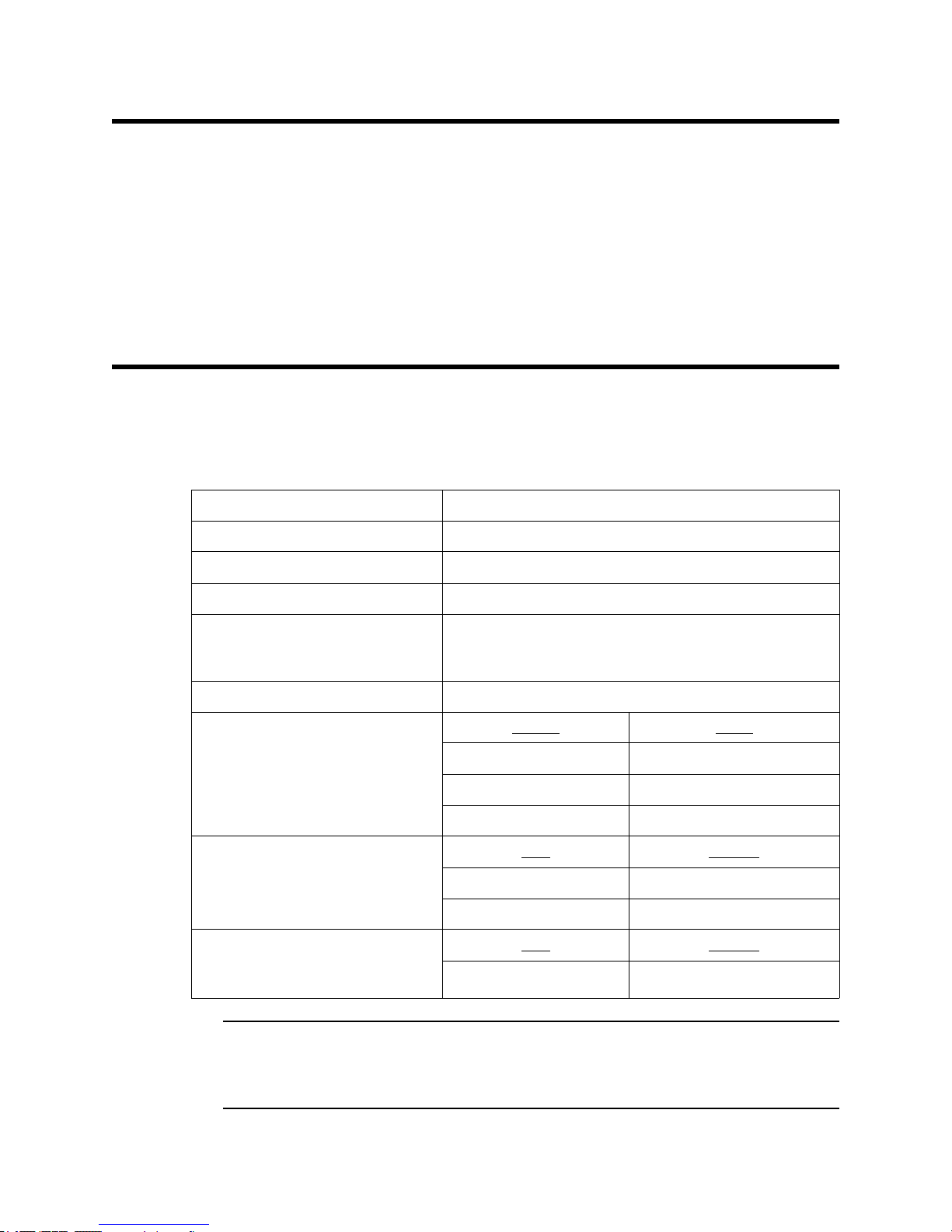
Specifications
Table 1 lists specifications for the sample-draw pump. See the detector head manual for
information specific to the detector head.
Input Power 24 VDC Nominal (18.5 VDC - 30 VDC)
Table 1: Specifications
Construction (housing) Fiberglass/polyester (NEMA 4X)
Dimensions 8.5 in. H x 6.5 in. W x 4.25 in. D
Weight 4.5 lbs.
Flow Rate • 3.0 SCFH recommended during operation
• 2.0 SCFH acceptable if tubing restriction from the
inlet and exhaust lines does not allow for 3.0 SCFH
Low Flow Setpoint 1.0 ± 0.1 SCFH
Low Flow Relay Contact Ratings
(resistive load)
Maximum Recommended Inlet/
Exhaust Line Length for
1/4” O.D. x 1/8” I.D. Tubing
Maximum Recommended Inlet/
Exhaust Line Length for
1/4” O.D. x 0.170” I.D. Tubing
Vo l t a g e
125 VAC 0.6 A
30 VDC 1 A
110 VDC 0.6 A
Inlet
30 feet 0 feet
15 feet 15 feet
Inlet
30 feet 30 feet
Amps
Exhaust
Exhaust
WARNING: When using the 35-3001-NS-03, you must follow the instructions and warnings
4 • 35-3001-NS-03 Sample-Draw Pump
in this manual to assure proper and safe operation of the 35-3001-NS-03 and to
minimize the risk of personal injury. Be sure to maintain and periodically
calibrate the 35-3001-NS-03 as described in this manual.
Page 5
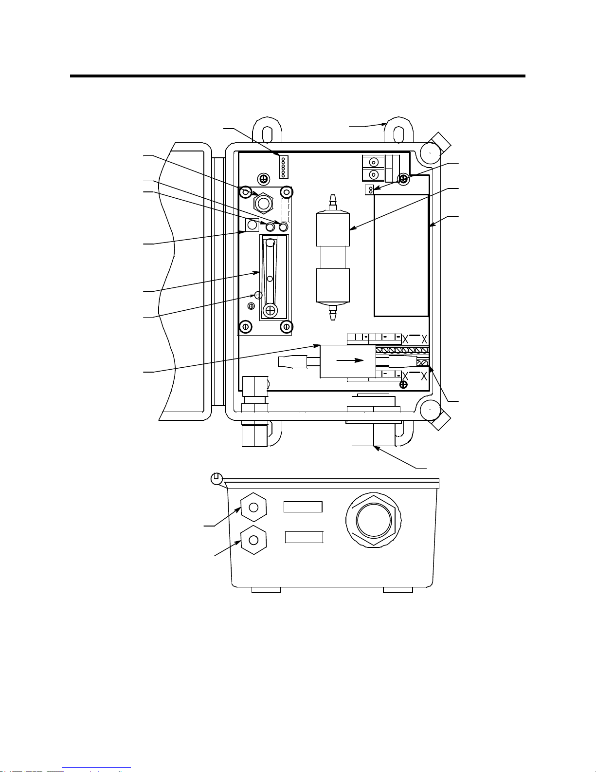
Description
Pump C onnector
Pump
_
O
X
Y
G
E
N
B
+
W
Flow Baffle
OXY
+
S
AM P 2
+
+
AM P
S
Sensor Flow
Control Valve
Fail LED
Pilot L ED
Interconnect
Terminal
Strip
Pump Reset
Switch
Flowmeter
Pressure Switch
Adjustment Screw
(behind PCB)
OXY
GW
+
3/4"Conduit Hub
AM P 2AM P 1
S
Particle Filter
Flowmeter Circuit
Board C onnector
LOW
FLOW
Exhaust
Fitting
Inlet
Fitting
LOW
FLOW
Mounting
Foot, 4X
EXHAUST
INLET
This section describes the components of the sample-draw pump.
Figure 1: Sample-Draw Pump Component Location
External Components
This section describes the sample-draw pump’s external components.
Housing
The sample-draw pump’s fiberglass housing is weather- and corrosion-resistant. It is suitable for
installation where general purpose equipment is in use.
35-3001-NS-03 Sample-Draw Pum p • 5
Page 6

The housing door is hinged on the left side and is secured by two latches on the right side. The
Flowmeter
Pump
Flow
Baffle
Flow
Control
Valve
Flowmeter
PCB
P
Pressure Switch
Particle Filter
Restrictor
Inlet
V
Exhaust
flowmeter and status LEDs are visible through a window in the housing door.
Four mounting feet are attached to the back of the housing (one at each corner). Use the mounting
feet to install the housing to a vertical surface.
Sample Fittings
The sample fittings are located on the left side of the bottom of the housing. The inlet fitting is near
the front of the housing and the exhaust fitting is near the back of the housing. The sample fittings
accept 1/4 in. rigid tubing. See the Installation section on page 8 to connect tubing to the sample
fittings.
Conduit Hub
One 3/4” conduit hub is located on the right side of the bottom of the housing. It is used for routing
wiring into the housing by using conduit or an appropriate cable bushing.
Internal Components
This section describes the sample-draw pump’s internal components (see Figure 1). Figure 2
illustrates how the gas sample moves through the flow system.
Main Circuit Board
The main circuit board includes the interconnect terminal strip, pump connector, and flowmeter
circuit board connector (see Figure 1).
Interconnect Terminal Strip
The interconnect terminal strip is the lower twelve-point terminal strip in the bottom right corner of
the main circuit board. Use the interconnect terminal strip to power the sample-draw pump and to
wire to the low flow contacts.
Pump Connector
The pump connector is the two-point connector below the oxygen terminal strip in the upper right
corner of the main circuit board. Use the pump connector to connect the pump to the main circuit
board.
6 • 35-3001-NS-03 Sample-Draw Pump
Figure 2: Sample-Draw Pump Flow Diagram
Page 7

NOTE: The pump is factory-wired to the main circuit board. See “Installation” on page 8 for all
wiring procedures related to the sample-draw pump.
Flowmeter Circuit Board Connector
The flowmeter circuit board connector is a six-position connector in the upper left corner of the
main circuit board. Use the flowmeter circuit board connector to connect the flowmeter circuit
board to the main circuit board.
NOTE: The flowmeter circuit board is factory wired to the main circuit board. See “Installation”
on page 8 for all wiring procedures related to the sample-draw pump.
Flowmeter Circuit Board
The flowmeter circuit board is mounted to the left side of the main circuit board using standoffs. It
includes the flowmeter, flow control valve, status LEDs, pressure switch, and pump reset switch.
Flowmeter
The flowmeter is mounted to the right side of the flowmeter circuit board. You can see it through
the window in the door. A ball in the flowmeter column indicates the flow rate through the system.
The flowmeter measures the flow in the range 0 to 10 SCFH (Standard Cubic Feet per Hour). The
optimum flow rate is 3 SCFH.
Flow Control Valve
The flow control valve is mounted to the flowmeter circuit board above the flowmeter. The flow
control valve adjusts the flow rate to the detector. Turn the valve’s knob counterclockwise to
increase the flow and clockwise to decrease the flow.
Status LEDs
Two status LEDs are above the flowmeter. They are also visible through the window in the housing
door. The green Pilot LED is on when the sample-draw pump is receiving power. The red Fail LED
is on when the sample flow rate is below the low flow level.
Pressure Switch
The pressure switch is mounted to the back of the flowmeter circuit board. The pressure switch
monitors the flow rate of the incoming gas sample.
If the flow rate falls below the preset low flow level, the pressure switch causes the Fail LED to
turn on. The low flow level is factory-set at 1.0 SCFH (±0.1 SCFH). See “Adjusting the Low Flow
Setting” on page 14 to adjust this setting.
Pump Reset Switch
The pump reset switch is located to the left of the status LEDs. When a low flow condition occurs,
the pump will be shut off. To reset the low flow condition and start the pump again, press and hold
the pump reset switch for about 2 seconds, then release.
Particle Filter
The particle filter is located along the bottom of the main circuit board. The filter prevents
particulates from damaging the flow system.
Pump
The pump is mounted to the right side of the main circuit board. The pump pulls the gas sample
into the sample-draw pump. The pump operates on 24 VAC, which is generated from the 24 VDC
supplied by the power source.
35-3001-NS-03 Sample-Draw Pum p • 7
Page 8

Installation
Ø .30x .50 (4X) MOUNTING
.78
1.13
.40
Pilot Fail
.85
.80
4.50
NOTE: Housing is4.3 inchesdeep
8.88
4.00
6.50
35-3001
www.rkiinstruments.com
Sam ple Drawing
G as D e t e cto r
8.50
Flow Baffle
A flow baffle is located in the middle of the main circuit board. Its function is to isolate the pressure
switch from vibrations in the flow line that are caused by the pump.
This section describes procedures to mount the sample-draw pump in the monitoring environment
and wire the sample-draw pump to a power source.
Mounting the Sample-Draw Pump
1. Select the mounting site. Consider the following when you select the mounting site:
• Is there enough room to open the housing door and make wiring and tubing connections at
the bottom of the housing?
• Make sure there is sufficient room to perform start-up and maintenance procedures.
• Are the flowmeter and status LEDs visible?
8 • 35-3001-NS-03 Sample-Draw Pump
Figure 3: Outline and Mounting Dimensions
Page 9

2. Close and latch the housing door.
1/4" Tube
Back Ferrule
Front Ferrule
Fitting B ody
Outsideof Case
1/4" Tube
O-ring
Tube Nut
Inside of Case
NOTE: The sample-draw pump is shipped with the mounting feet “tucked under” the housing to
protect the mounting feet during shipment.
3. Slightly loosen the screw that secures the mounting foot to the housing, then rotate the
mounting foot 180 degrees (see Figure 3).
4. Tighten the screw that secures the mounting foot to the housing.
5. Repeat steps 3 and 4 for the remaining three mounting feet.
6. Position the sample-draw housing on a vertical surface at eye level (4 1/2 to 5 feet from the
floor).
7. Insert 1/4 inch screws through the slots in the mounting feet to secure the housing to the
mounting surface.
Connecting the Sample Lines to the Sample-Draw Pump
Installing the Inlet Line
1. Loosen the nut on the inlet fitting until 3 threads are visible.
2. Push 1/4” O.D. rigid polypropylene or rigid Teflon sample tubing into the fitting until it stops.
Flexible polyurethane tubing may be used with an appropriate insert. RKI Instruments, Inc.
recommends using either 1/4” O.D. x 1/8” I.D. or 1/4” O.D. x 0.170” I.D. tubing based on your
length requirements. See “Specifications” on page 4 for maximum tubing lengths based on
tubing size.
CAUTION: If you use flexible sample tubing (polyurethane is acceptable), use an appropriate
insert to seal the connection between the tubing and the inlet fittin g.
Figure 4: Fitting Arrangement
35-3001-NS-03 Sample-Draw Pum p • 9
Page 10

3. Hand tighten the nut on the inlet fitting so the ferrules clamp on the tubing. If the tube nut is
removed, see Figure 4 for the arrangement of the fitting components.
4. Route tubing from the sample-draw pump’s inlet fitting to the flow through adapter’s exhaust
fitting. See “Specifications” on page 4 for maximum tubing lengths based on tubing size.
CAUTION: Avoid lo ops or slumps in the incoming sa mple line. To reduce response time, keep the
incoming sample line as short as possible.
Installing the Exhaust Line
1. Loosen the nut on the exhaust fitting until 3 threads are visible.
2. Push 1/4” O.D. rigid polypropylene or rigid Teflon sample tubing into the fitting until it stops.
Flexible polyurethane tubing may be used with an appropriate insert. RKI Instruments, Inc.
recommends using either 1/4” O.D. x 1/8” I.D. or 1/4” O.D. x 0.170” I.D. tubing based on your
length requirements. See “Specifications” on page 4 for maximum tubing lengths based on
tubing size.
CAUTION: If you use flexible sample tubing (polyurethane is acceptable), use an appropriate
insert to seal the connection between the tubing and the inlet fittin g.
3. Hand tighten the nut on the exhaust fitting so the ferrules clamp on the tubing. If the tube nut is
removed, see Figure 4 for the arrangement of the fitting components.
4. Route the opposite end of the tubing to an open area where the sample can safely disperse or to
an exhaust duct. See “Specifications” on page 4 for maximum tubing lengths based on tubing
size.
Wiring the Sample-Draw Pump to a Power Source
WARNING: Always verify that the power source is off before you make wiring connections.
1. Turn off the power source.
2. Unlatch and open the housing door of the sample-draw pump.
3. Guide a four-conductor, shielded cable or four wires in conduit through the conduit hub at the
bottom of the sample-draw housing. A minimum of 18 AWG wire is recommended.
4. Connect the cable to the sample-draw pump’s interconnect terminal strip as shown in Figure 5.
5. Close and latch the housing door.
6. Route the cable or wires in conduit leading from the sample-draw pump to the power source.
10 • 35-3001-NS-03 Sample-Draw Pump
Page 11

7. Connect the wires to the power source as shown in Figure 5.
AMP 1
LOW
FLOW
AMP 2
LOW
FLOW
AMP 1
OXY
AMP 2
OR
OXY
+ 24 VDC
- (DCGround)
Not Used
Resistive
Load D evice
Contact
Monitoring
Dev ice
Power
Low Flow
Relay Co ntact Ratings:
125 VAC 0.6A
30 VDC 1A
110 VD C 0.6A
Figure 5: Wiring the Sample-Draw Pump to a Power Source
35-3001-NS-03 Sample-Draw Pump • 11
Page 12

Start Up
8. Connect a contact monitoring device or some other device to the low flow contacts. Do not
exceed the relay ratings below. The ratings are for a resistive load.
Table 2: Low Flow Relay Specifications
Voltage Amps
125 VAC 0.6 A
30 VDC 1 A
110 VDC 0.6 A
See “Low Flow Contact Operation” on page 13 for a description of how to use the low flow
contacts.
This section describes procedures to start up the sample-draw pump and place the sample-draw
pump into normal operation.
Introducing Incoming Power
1. Complete the installation procedures described earlier in this manual.
2. Verify that the wiring is correct and secure.
3. Turn on or plug in the power source.
4. Verify that the sample-draw pump’s Pilot LED is on.
5. Use the flow control valve to set the flow rate to 3.0 SCFH. If the inlet and exhaust tubing
restriction does not allow for a flow rate of 3.0 SCFH, a flow rate of 2.0 SCFH still provides
good sensor response at the flow through adapter. RKI Instruments, Inc. does not recommend a
flow rate of lower than 2.0 SCFH. Turn the valve’s knob counterclockwise to increase the flow
and clockwise to decrease the flow.
NOTE: The following step tests for leaks in the sample line. This test will cause a low flow
condition at the sample-draw pump. Disable the device connected to the low flow
contacts before performing this test.
6. Verify that the incoming sample line is not leaking. To test the sample line, press and hold the
reset switch and plug the open end of the sample line with your thumb. If the flowmeter ball
drops to the bottom of the flowmeter, the incoming sample line is not leaking.
7. Remove your thumb from the sample line, release the reset switch, and verify the flowmeter
returns to a normal flow rate.
8. Follow startup instructions in the detector head manual and flow through adapter manual.
12 • 35-3001-NS-03 Sample-Draw Pump
Page 13

Low Flow Contact Operation
The low flow contact is closed during normal operation and opens during a low flow condition or if
the sample-draw pump loses power.
Monitoring of the low flow contacts can be done with a contact monitoring device that does not
exceed the relay ratings below. Alternatively, the contacts could be used to power a device that does
not exceed the relay contact ratings below. The ratings are for a resistive load.
Table 3: Low Flow Relay Specifications
Voltage Amps
125 VAC 0.6 A
30 VDC 1 A
110 VDC 0.6 A
Maintenance
This section describes maintenance procedures. It includes preventive maintenance procedures.
This section also includes procedures to troubleshoot the sample-draw pump, replace components
of the sample-draw pump, adjust the low flow setting, and remove the particle filter’s tubing stub.
Daily Preventive Maintenance
1. Verify that the Pilot LED is on.
2. Verify that the flowmeter indicates a flow rate between 2.0 and 3.0 SCFH. See
“Specifications” on page 4 for more discussion of an appropriate flow rate. If necessary use the
flow control valve to adjust the flow rate. Turn the valve’s knob counterclockwise to increase
the flow and clockwise to decrease the flow.
Troubleshooting
The troubleshooting guide describes symptoms, probable causes, and recommended action for
problems you may encounter with the sample-draw pump.
NOTE: This troubleshooting guide describes sample-draw pump problems only. See the detector
head if the detector head exhibits any problems.
Fail Condition
Symptoms
• The sample-draw pump’s Fail LED is on.
Probable causes
• The sample-draw pump’s flow rate is too low because of an obstructed sample line, failed
pump, etc.
• The sample-draw pump is malfunctioning.
Recommended action
1. At the sample-draw pump, set the correct flow rate with the flow control valve.
2. If you cannot set the correct flow rate, check the sample lines for obstructions or kinks.
35-3001-NS-03 Sample-Draw Pump • 13
Page 14

3. If the fail condition continues, contact RKI Instruments, Inc. for further instruction.
Slow or No Response/Difficult or Unable to Calibrate
Symptoms
• The detector head that the pump is drawing sample through responds slowly or does not
respond.
• Unable to accurately set the zero or response reading during calibration.
• The detector head requires frequent calibration.
• Flow rate cannot be set between 2.0 and 3.0 SCFH.
Probable causes
• The sample-draw pump’s flow rate is too low because of an obstructed sample line, failed
pump, etc.
• The sample-draw pump is malfunctioning.
Recommended action
1. If necessary, set the correct flow rate with the flow control valve.
2. If you cannot set the correct flow rate, check the sample line for obstructions or kinks.
3. If the detector head calibration/response difficulties continue, contact RKI Instruments, Inc. for
further instruction.
Replacing the Particle Filter
1. Turn off the power source.
2. Disconnect the grey tubing at each end of the particle filter from the flow system tubing.
3. Remove the old particle filter.
4. Install the new particle filter. Be sure the arrow on the particle filter is pointing away from the
tubing coming from the inlet fitting.
5. Turn on the power source.
Adjusting the Low Flow Setting
NOTE: Adjusting the low flow setting will cause a low flow alarm at the sample-draw pump.
Disable the device connected to the low flow contacts before performing this test.
The factory-set low flow setting is 1.0 SCFH (±0.1). To adjust the low flow setting:
1. Use the flow control valve to set the flow to 1.0 SCFH. Turn the valve’s knob
counterclockwise to increase the flow and clockwise to decrease the flow.
If the sample-draw pump goes into low flow alarm before you can adjust the flow down to 1.0
SCFH, adjust the pressure switch adjustment screw 1/4 turn clockwise, then attempt to set the
flow again. Repeat this step until you are able to adjust the flow to 1.0 SCFH.
NOTE: The pressure switch adjustment screw is accessible through a circular cutout in the
flowmeter circuit board.
2. Slowly turn the pressure switch adjustment screw counterclockwise just until the sample-draw
pump goes into low flow alarm.
14 • 35-3001-NS-03 Sample-Draw Pump
Page 15

Parts List
3. Turn the flow control valve’s knob counterclockwise to increase the flow until the unit is out of
low flow alarm when the reset switch is pressed and released.
4. Decrease the flow very slowly by turning the flow control valve’s knob clockwise and verify
that the low flow alarm is 1.0 SCFH (±0.1).
If the low flow alarm is set too high, turn the pressure switch adjustment screw slightly
clockwise. Repeat steps 3 and 4 if necessary.
5. Use the flow control valve to set the flow between 2.0 and 3.0 SCFH. See “Specifications” on
page 4 for more discussion of an appropriate flow rate.
6. Make sure the sample-draw pump’s Fail LED is off.
Table 4 lists replacement parts and accessories for the sample-draw pump.
Table 4: Parts List
Part Number Description
06-1248RK Sample tubing, 3/16” ID x 5/16” OD, specify length
06-1248RK-03 Sample tubing, 3/16” ID x 5/16” OD, 3 feet (for calibration kit)
17-2670 Inlet fitting O-ring
17-2671 Inlet fitting front ferrule
17-2672 Inlet fitting back ferrule and tube nut
30-1016RK Pump
33-0167RK Particle filter
71-0472 Operator’s Manual, 35-3001-NS-03 Sample-Draw Pump
81-1054RK Regulator, demand flow, for 34 liter aluminum, 58 liter, and 103 liter
calibration cylinders (cylinders with internal threads)
81-1055RK Regulator, demand flow, for 17 liter and 34 liter steel calibration cylinders
(cylinders with external threads)
35-3001-NS-03 Sample-Draw Pump • 15
 Loading...