

Page 1

35-3001A-09
Oxygen/Hydrogen Sulfide
Sample-Draw Detector
Operator’s Manual
Part Number: 71-0311RK
Revision: P3
Released: 9/17/14
www.rkiinstruments.com
Page 2

WARNING
Read and understand this instruction manual before operating
detector . Improper use of the dete ctor could result in bodily harm
or death.
Periodic calibration and maintenance of the detector is essential
for proper operation and correct readings. Please calibrate and
maintain this detector regularly! Frequency of calibration
depends upon the type of use you have and the sensor types.
T ypical calibration frequencies for most applications a re between
3 and 6 months, but can be required more often or less often
based on your usage.
35-3001A-09 Oxygen/Hydrogen Sulfide Sample -Draw Detector
Page 3

Product Warranty
RKI Instruments, Inc. warrants gas alarm equipment s old by us t o be free from def ects in material s,
workmanship, and performance for a period of one year from date of shipment from RKI
Instruments, Inc. Any parts found defective within that period will be repaired or replaced, at our
option, free of charge. This warrant y does not apply to those items which by their nature are subject
to deterioration or consumption in normal service, and which must b e cleaned, repaired, o r replaced
on a routine basis. Examples of such items are:
Warranty is voided by abuse including mechanical damage, alteration, rough handling, or repair
procedures not in accordance with the operator’s manual. This warranty indicates the full extent of
our liability, and we are not responsible for removal or replacement costs, local repair costs,
transportation costs, or contingent expenses incurred without our prior approval.
THIS WARRANTY IS EXPRESSLY IN LIEU OF ANY AND ALL OTHER
WARRANTIES AND REPRESENTATIONS, EXPRESSED OR IMPLIED, AND
ALL OTHER OBLIGATIONS OR LIABILITIES ON THE PART OF RKI
INSTRUMENTS, INC. INCLUDING BUT N OT LIMITED T O, THE WARRANTY
OF MERCHANTABILITY OR FITNESS FOR A PARTICULAR PURPOSE. IN
NO EVENT SHALL RKI INSTRUMENTS, INC. BE LIABLE FOR INDIRECT,
INCIDENTAL, OR CONSEQUENTIAL LOSS OR DAMAGE OF ANY KIND
CONNECTED WITH THE USE OF ITS PRODUCTS OR FAILURE OF ITS
PRODUCTS TO FUNCTION OR OPERATE PROPERLY.
a) Absorbent cartridges d) Batteries
b) Pump diaphragms and valves e) Filter elements
c) Fuses
This warranty covers instruments and parts sold to users by authorized distributors, dealers, and
representatives as appointed by RKI Instruments, Inc.
We do not assume indemnification for any accident or damage caused by the operation of this gas
monitor, and our warranty is limited to the replacement of parts or our complete goods.
35-3 001A-09 Oxygen/Hydrogen Sulfide Sample- Draw Detector
Page 4

Table of Contents
Overview . . . . . . . . . . . . . . . . . . . . . . . . . . . . . . . . . . . . . . . . . . . . . . . . . . . . . . . . . . . . . . . . . . . . 1
Specifications. . . . . . . . . . . . . . . . . . . . . . . . . . . . . . . . . . . . . . . . . . . . . . . . . . . . . . . . . . . . . . . . . 1
Description. . . . . . . . . . . . . . . . . . . . . . . . . . . . . . . . . . . . . . . . . . . . . . . . . . . . . . . . . . . . . . . . . . . 2
External Components. . . . . . . . . . . . . . . . . . . . . . . . . . . . . . . . . . . . . . . . . . . . . . . . . . . . . . . . . . . . . . . . . . . . 3
Internal Components . . . . . . . . . . . . . . . . . . . . . . . . . . . . . . . . . . . . . . . . . . . . . . . . . . . . . . . . . . . . . . . . . . . . 5
Installation. . . . . . . . . . . . . . . . . . . . . . . . . . . . . . . . . . . . . . . . . . . . . . . . . . . . . . . . . . . . . . . . . . . 8
Mounting the Sample-Draw Detector . . . . . . . . . . . . . . . . . . . . . . . . . . . . . . . . . . . . . . . . . . . . . . . . . . . . . . . 8
Removing the Inlet Fitting Tubing Stub, if Necessary . . . . . . . . . . . . . . . . . . . . . . . . . . . . . . . . . . . . . . . . . . 9
Connecting the Sample Lines to the Sample-Draw Detector . . . . . . . . . . . . . . . . . . . . . . . . . . . . . . . . . . . . 10
Wiring the Sample-Draw Detector to a Controller . . . . . . . . . . . . . . . . . . . . . . . . . . . . . . . . . . . . . . . . . . . . 11
Start Up . . . . . . . . . . . . . . . . . . . . . . . . . . . . . . . . . . . . . . . . . . . . . . . . . . . . . . . . . . . . . . . . . . . . 13
Introducing Incoming Power. . . . . . . . . . . . . . . . . . . . . . . . . . . . . . . . . . . . . . . . . . . . . . . . . . . . . . . . . . . . . 13
Setting the Zero Reading. . . . . . . . . . . . . . . . . . . . . . . . . . . . . . . . . . . . . . . . . . . . . . . . . . . . . . . . . . . . . . . . 13
Maintenance . . . . . . . . . . . . . . . . . . . . . . . . . . . . . . . . . . . . . . . . . . . . . . . . . . . . . . . . . . . . . . . . 14
Preventive Maintenance. . . . . . . . . . . . . . . . . . . . . . . . . . . . . . . . . . . . . . . . . . . . . . . . . . . . . . . . . . . . . . . . . 14
Troubleshooting. . . . . . . . . . . . . . . . . . . . . . . . . . . . . . . . . . . . . . . . . . . . . . . . . . . . . . . . . . . . . . . . . . . . . . . 16
Replacing Components of the Sample-Draw Detector . . . . . . . . . . . . . . . . . . . . . . . . . . . . . . . . . . . . . . . . . 17
Adjusting the Low Flow Setting . . . . . . . . . . . . . . . . . . . . . . . . . . . . . . . . . . . . . . . . . . . . . . . . . . . . . . . . . . 20
Calibration Frequency . . . . . . . . . . . . . . . . . . . . . . . . . . . . . . . . . . . . . . . . . . . . . . . . . . . . . . . . 21
Calibration, Oxygen Sensor. . . . . . . . . . . . . . . . . . . . . . . . . . . . . . . . . . . . . . . . . . . . . . . . . . . . 21
Preparing for Calibration. . . . . . . . . . . . . . . . . . . . . . . . . . . . . . . . . . . . . . . . . . . . . . . . . . . . . . . . . . . . . . . . 21
Setting the Fresh Air Reading . . . . . . . . . . . . . . . . . . . . . . . . . . . . . . . . . . . . . . . . . . . . . . . . . . . . . . . . . . . . 21
Setting the Zero Reading. . . . . . . . . . . . . . . . . . . . . . . . . . . . . . . . . . . . . . . . . . . . . . . . . . . . . . . . . . . . . . . . 22
Returning to Normal Operation. . . . . . . . . . . . . . . . . . . . . . . . . . . . . . . . . . . . . . . . . . . . . . . . . . . . . . . . . . . 22
Calibration, H2S Sensor. . . . . . . . . . . . . . . . . . . . . . . . . . . . . . . . . . . . . . . . . . . . . . . . . . . . . . . 22
Preparing for Calibration. . . . . . . . . . . . . . . . . . . . . . . . . . . . . . . . . . . . . . . . . . . . . . . . . . . . . . . . . . . . . . . . 22
Setting the Zero Reading. . . . . . . . . . . . . . . . . . . . . . . . . . . . . . . . . . . . . . . . . . . . . . . . . . . . . . . . . . . . . . . . 23
Setting the Response Reading . . . . . . . . . . . . . . . . . . . . . . . . . . . . . . . . . . . . . . . . . . . . . . . . . . . . . . . . . . . . 23
Returning to Normal Operation. . . . . . . . . . . . . . . . . . . . . . . . . . . . . . . . . . . . . . . . . . . . . . . . . . . . . . . . . . . 23
Parts List . . . . . . . . . . . . . . . . . . . . . . . . . . . . . . . . . . . . . . . . . . . . . . . . . . . . . . . . . . . . . . . . . . . 24
35-3001A-09 Oxygen/Hydrogen Sulfide Sample -Draw Detector
Page 5
Overview
This operator’s manu al descri bes th e 35-30 01A-09 oxygen /hydr ogen sul fide s ample-d raw detecto r.
This manual also describes how to install, start up, maintain, and calibrate the sample-draw detector
when using it with a gas monitoring controller. A parts list at the end of this manual lists
replacement parts and accessories for the sample-draw detector.
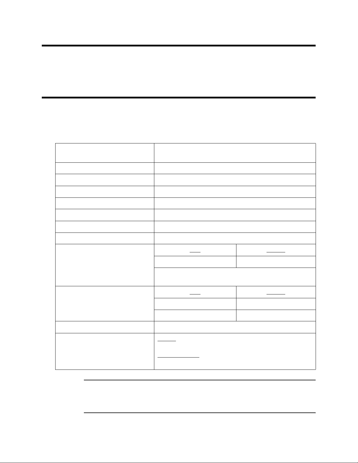
Specifications
Table 1 lists specifications for the oxygen/hydrogen sulfide sample-draw detector. See the
controller Operator’s Manual for information specific to the controller.
Table 1: Specifications
Target Gases and Detection Range Oxygen: 0 - 25% volume
Hydrogen Sulfide: 0 - 100 ppm
Input Power 24 VDC Nominal (18.5 VDC - 30 VDC)
Construction (housing) Fiberglass/polyester (NEMA 4X)
Dimensions 8.5 in. H x 6.5 in. W x 4.25 in. D
Weight 4.5 lbs.
Sampling Method Sample-draw
Sample Flow 3.0 SCFH typical, with no inlet or exhaust line
Flow to Sensor 1.0 SCFH (nominal)
Maximum Recommended Inlet/
Exhaust Line Length for
1/4” O.D. x 1/8” I.D. Tubing
* RKI Instruments, Inc. does not recommend installing this tubing
size on both the inlet and exhaust.
Maximum Recommended Inlet/
Exhaust Line Length for
1/4” O.D. x 0.170” I.D. Tubing
Response Time 90% in 30 seconds
Accuracy Oxygen
± 0.5 % O
Hydrogen Sulfide:
± 5% of reading or ± 2 ppm H
Inlet
50 feet 0 feet
Inlet
50 feet 50 feet
75 feet 0 feet
:
2
S (whichever is greater)
2
Exhaust
Exhaust
WARNING: When using the 35-3001A-09, you must fo llow the instructions and warnings in
this manual to assure proper and safe operation of the 35-3001A-09 and to
minimize the risk of personal injury. Be sure to maintain and periodically
calibrate t h e 35-3001A- 09 as describe d in this manual.
35-3001A-09 Oxygen/Hydrogen Sulfide Sample-Draw Detecto r • 1
Page 6
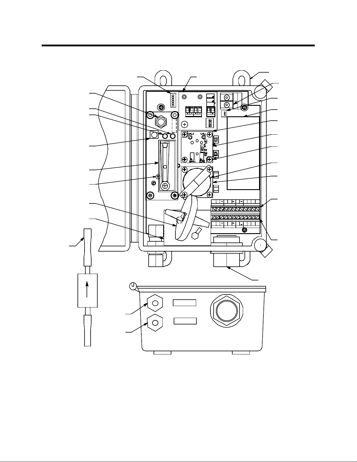
Description
Sens or Flow
Control Valve
Fail LED
Pilot LED
This section describes th e components of the oxygen/hydrogen sulfide sample-draw detector.
Mounting
Flowmeter Circuit
Board Connecto r
Oxygen Amplifier
TOXIC
OXY
S
SIG/PWR
O
W
X
+
Y
G
E
B
_
N
Foot, 4X
Oxygen Sensor
Terminal Strip
Pump Connector
Pump
H2S Sensor
(inside block)
H2S Amplifier
Pump Reset
Pressure Switch
Adjustment Screw
(behind PC B)
Hydrophobic
Flow Baffle
This End To
Inlet Fitting
Particle Filter
Switch
Flowmeter
Filter
Inlet
Fitting
INLET
EXHAUST
H2S Fl o w
Block
Oxygen
Sensor
Oxygen Flow
Block
BGS
RS
+
+
AMP
AMP 2
W
+
OXY
LEL/ IR
Detector/Amp
Terminal Strip
(Factory Wired)
+
AMP 2
GW
W
+
OXY
LEL/ IR
S
+
AMP 1
R
BGS
Interconnect
Terminal
Strip
3/4" Conduit Hub
Exhaust
Fitting
Figure 1: Oxygen/Hydrogen Sulfide Sample-Draw Detector Component Location
External Components
This section describes the sample-draw detector’s external components.
Housing
The sample-draw detector’s fiberglass housing is weather- and corrosion-resistant. It is suitable fo r
2 • 35-3001A-09 Oxygen/Hydroge n Sulfide Sample- Draw Detector
Page 7
installation where general purpose equipment is in use.
The housing door is hinged on the left side and is secured by two latches on the right side. The
flowmeter and status LEDs are visible through a window in the housing door.
Four mounting feet are attached to the back of the housing (one at each corner). Use the mounting
feet to install the housing to a vertical surface.
Sample Fittings
The sample fittings are located on the left side of the bottom of the housing. The inlet fitting is near
the front of the housing and the exhaust fitting is near the back of the housing. The inlet fitting has
a short factory installed tubing stub for use with the particle filter. The sample fittings accept 1/4 in.
rigid tubing. See the Installation section on page 8 to connect tubing to the sample fittings.
Inlet Fitting Tubing Stub
A short tubing stub comes factory installed in the inlet fittin g. It is used for connecting the particle
filter. If the particle filter is not used, or if you install the particle filter in a different location, the
tubing stub needs to be removed and replaced with tubing.
Conduit Hub
One 3/4” conduit hub is located on the right sid e of the bottom of the hous ing. It is used fo r routing
wiring into the housing by using conduit or an appropriate cable bushing.
Internal Components
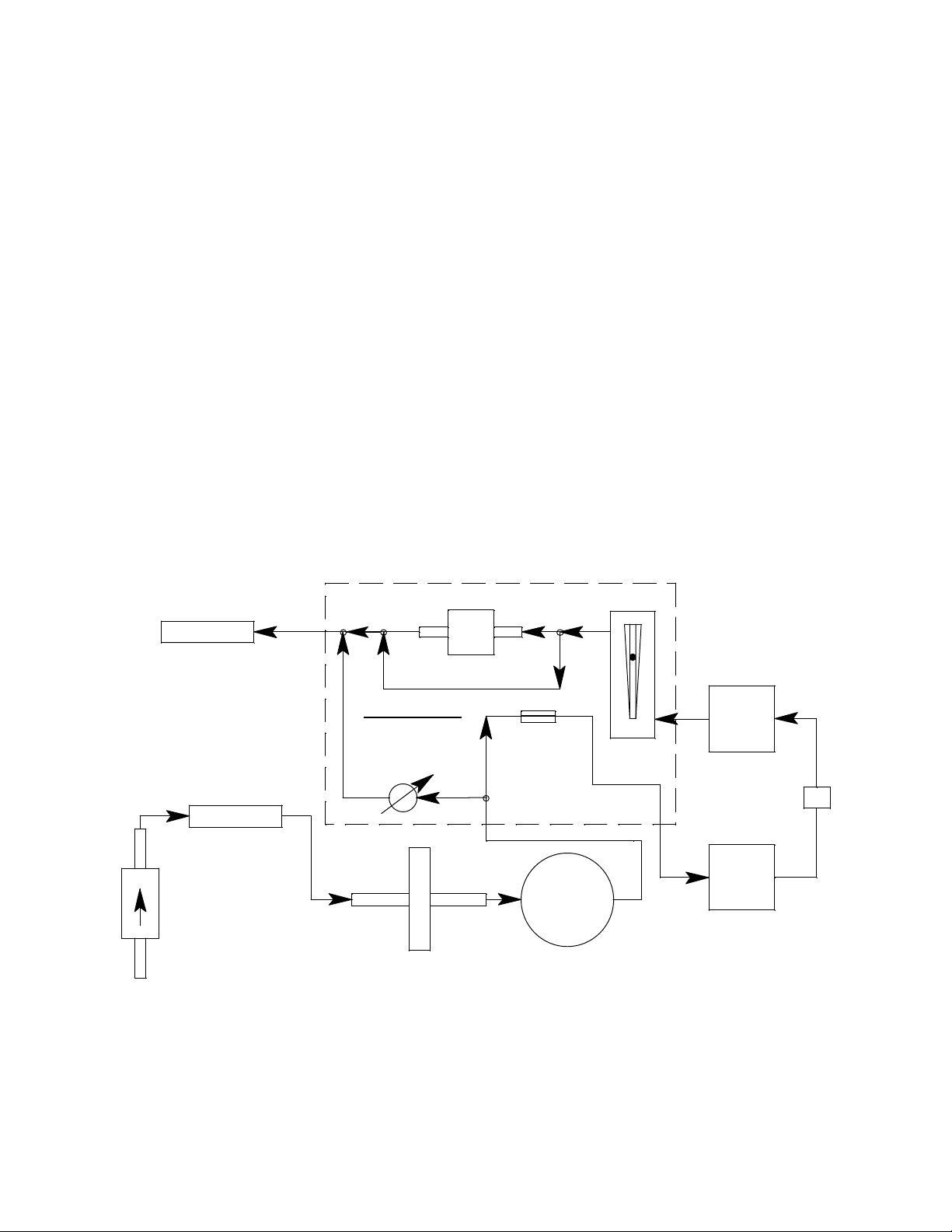
This section describes the sample-draw detector’s internal components (see Figure 1). Figure 2
illustrates how the gas sample moves through the flow system.
Exhaust
Inlet
Particle Filter
Pressure Switch
Flowmeter PCB
Sensor Flow
Control Valve
Hydrop hob i c Fil ter
Restrict or
Pump
Flowmeter
H2S
Sensor
Flow Baffle
Oxygen
Sensor
Figure 2: Oxygen/Hydrogen Sulfide Sample-Draw Detector Flow Diagram
Main Circuit Board
The main circuit board includes the detect or/amp terminal strip, intercon nect terminal st rip, oxygen
sensor terminal strip, pump connector, and flowmet er circuit board connector (see Figure 1).
35-3001A-09 Oxygen/Hydrogen Sulfide Sample-Draw Detecto r • 3
Page 8

Detector/Amp Terminal Strip
The detector/amp terminal strip is the upper twelve-point terminal strip in the bot tom right corner
of the main circuit board. Use the detector/amp terminal strip to connect the oxygen sensor to the
oxygen amplifier and to connect the oxygen amplifier and the hydrogen sulfide sensor to the main
circuit board.
NOTE: The oxygen sensor is factory wired to the oxygen sensor terminal strip and the oxygen
amplifier and the hydrogen sulfide sensor are factory-wired to the main circuit boar d. See
the “Installation” section on page 8 for all wiring procedures related to the sample-draw
detector.
Interconnect Terminal Strip
The interconnect terminal strip is the lower twelve-point terminal strip in the bottom right corner of
the main circuit board. Use the interconnect termin al stri p to con n ect the sam ple-draw detector to a
controller.
Oxygen Sensor Terminal Strip
The oxygen sensor terminal strip is a two-point terminal strip in the upper right corner of the main
circuit board. Use the oxygen sensor terminal strip to connect the oxygen sensor to the main circuit
board.
NOTE: The oxygen sensor is factory-wired to the main circuit board. See the “Installation”
section on page 8 for all wiring procedures related to the sample-draw detector.
Pump Connector
The pump connector is the two-point connector below the oxygen terminal strip in the upper right
corner of the main circuit board. Use the pump co nnector to connect the pump to the main circuit
board.
NOTE: The pump is factory-wired to the main circuit board. See “Installation” on page 8 for all
wiring procedures related to the sample-draw detector.
Flowmeter Circuit Board Connector
The flowmeter circuit board connector is a six-position connector in the upper left corner of the
main circuit board. Use the flowmeter circuit board connector to connect the flowmeter circuit
board to the main circuit board.
NOTE: The flowmeter circuit board is factory wired to the main circuit board. See “Installation”
on page 8 for all wiring procedures relate d to the samp le-draw detector.
Flowmeter Circuit Board
The flowmeter circuit board is mounted to the left side of the main circuit board using standoffs. It
includes the flowmeter, sensor flow control valve, status LEDs, pressure switch, and pump reset
switch.
Flowmeter
The flowmeter is mounted to the right side of the flowmeter circuit board. You can see it through
the window in the door. A ball in the flowmeter column indicates the flow rate to the sensor. The
flowmeter measures the flow in the range 0.2 to 2.0 SCFH (Standard Cubic Feet per Hour). The
optimum flow rate is 1.0 SCFH.
4 • 35-3001A-09 Oxygen/Hydroge n Sulfide Sample- Draw Detector
Page 9

Sensor Flow Control Valve
The sensor flow control valve is mounted to the flowmeter circuit board above the flowmeter. The
sensor flow control valve adjusts the flow rate to the detector. Turn the valve’s knob clockwise to
increase the flow and counterclockwise to decrease the flow.
Status LEDs
T wo status LEDs are abov e the flowmeter. They are also visible through the windo w in t he hou sing
door. The green Pilot LED is on when the sample-draw detector is receiving power from the
controller. The red Fail LED is on when the sample flow rate is below the low flow level.
Pressure Switch
The pressure switch is mounted to the back of the flowmeter circuit board. The pressure switch
monitors the flow rate of the incoming gas sample.
If the flow rate falls below the preset low flow level, the pressure switch causes the Fail LED to
turn on and interrupts the signal from the detector. The interrupted detector signal causes a fail
condition at the controller. The low flow level is factory-set at 0.6 SCFH (±0.1 SCFH). See
“Adjusting the Low Flow Setting” on page 20 to adjust this setting.
Pump Reset Switch
The pump reset switch is located to the left of the status LEDs. When a low flow condition occurs,
the pump will be shut off. To reset the low flow condition and start the pump again, press and hold
the pump reset switch for about 2 seconds, then release.
Hydrophobic Filter
The hydrophobic filter is located toward the bottom left of the main circuit board. The filter
prevents particulates and water in the incoming gas sample from damaging the flow and detection
systems. Replace the filter when it appears dirty, discolored, or clogged.
Pump
The pump is mounted to the right side of the main circuit board. The pump pulls the gas sample
into the sample-draw detector. The pump operates on 24 VAC, which is generated from the 24
VDC supplied by the controller.
Oxygen Sensor
The oxygen sensor is installed in a flow block and the flow block is mounted to the middle of the
main circuit board. It is the lower of the two flow blocks mounted to the main circuit board. The
oxygen sensor is retained in the flow block by a bracket with two screws.
The oxygen cell is protected within the sensor assembly. Through a series of chemical and
electronic reactions, the oxygen cell produces a millivolt output that is proportional to the detection
range of the sample-draw detector. The leads extending from the sensor terminate in lugs that
connect to the oxygen terminal strip.
35-3001A-09 Oxygen/Hydrogen Sulfide Sample-Draw Detecto r • 5
Page 10

Oxygen Amplifier
The amplifier converts the electrical output from the detector to a 4 to 20 mA signal that
corresponds to the detection range and transmits the signal to a gas monitoring controller. The
amplifier is mounted on the top middle edge of the main circuit board. It consists of the zero pot,
span pot, controller terminal strip, detector terminal strip, and test points.
Test Points
100-500 mV Range
Zero Pot
Span Pot
Factory Set Pot
Detector
Terminal
Strip
TOXIC
OXY
Figure 3: Oxygen Amplifier Component Location
Zero Pot
The zero pot is located in the upper right corner of the amplifier (see Figure 3). Use a small flat
blade screwdriver to turn the zero pot’s adjustment screw and adjust the amplifier’s zero (oxygen
free) output during the calibration procedure. Turn the adjustment screw clockwise to increase the
zero output and counterclockwise to decrease the zero output.
Span Pot
The span pot is located below the zero pot (see Figure 3). Use a small flat blade screwdriver to turn
the span pot’s adjustment screw and adjust the amplifier’s fresh air output duri ng th e start up and
calibration procedure. Turn the adjustment screw clockwise to increase the fresh air output and
counterclockwise to decrease the fresh air output.
S
SIG/PWR
Controller
Terminal Strip
CAUTION: The amplifier includes an additional pot. It is factory-set. Do not adjust it.
Controller and Detector Terminal Strips
The controller terminal strip and detector terminal strip are two- and four-position plug-in style
terminal strips, respectively. The controller terminal strip is located on the right side of the
amplifier and the detector terminal strip is to the left of it. Both terminal strips are factory wired to
the detector/amp terminal strip on the main circuit board.
T est Points
The test points are on the left side of the amplifier (see Figure 3). The test points produce a 100 mV
to 500 mV output that corresponds to the sample-draw detector’s 4 to 20 mA output. Use the test
points and a voltmeter to measure the amplifier’s output during the start-up and calibration
procedures. The black test point in the upper left corner is the negative (-) test point and the red test
point to the left of the zero and span pots is the positive (+) test point.
Flow Baffle
A flow baffle is located in front of the hydrogen sulfide sensor. Its function is to isolate the
hydrogen sulfide sensor from vibrations in the flow line that are caused by the pump.
6 • 35-3001A-09 Oxygen/Hydroge n Sulfide Sample- Draw Detector
Page 11
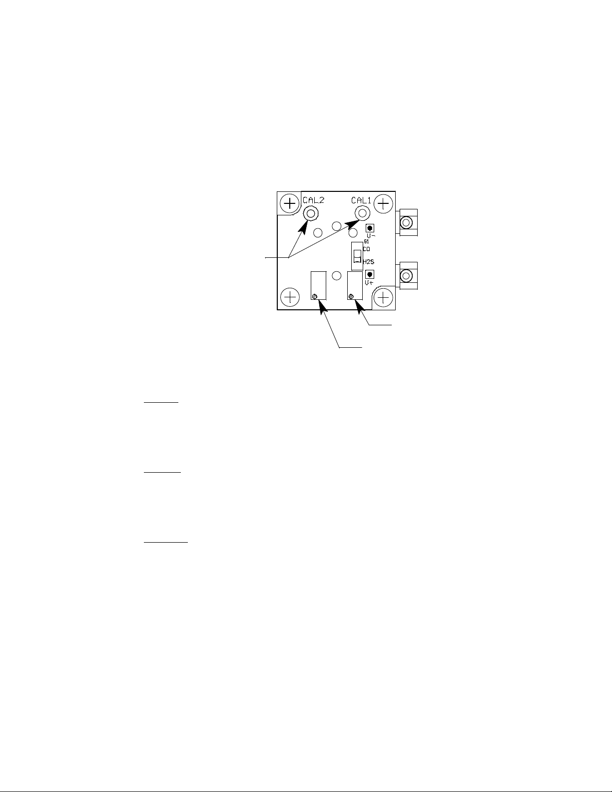
Hydrogen Sulfide Sensor/H2S Amplifier
The hydrogen sulfide sensor is a plug-in sensor that plugs into the back of the H2S amplifier. The
sensor and amplifier ar e re tained in the flow block b y two screws . The f low blo ck is mount ed to t he
middle of the main circuit board. It is the upper of t he tw o flow bl ock s mo unted to the main circuit
board.
Through a series of chemical and electronic reactions, the H
that is proportional to the detection range of the sample-draw detector. A red wire and a blue wire
extend from the H
S amplifier and allow connection to the detector/amp terminal strip.
2
S sensor produces a millivolt output
2
Test Points
100-500 mV Range
Zero Pot
Sp an Pot
Figure 4: H
Zero Pot
The zero pot is located in the lower right corner of the amplifier (see Figure 4). Use a small flat
blade screwdriver to turn the zero pot’s adjustment screw and adjust the amplifier’s zero output
during the start up and calib rat ion p roced ures . Turn the adjustment screw clockwise to increase the
zero output and counterclockwise to decrease the zero output.
S Amplifier Component Location
2
Span Pot
The span pot is located to the left of the zero pot (see Figure 4). Use a small flat blade screwdri ver
to turn the span pot’s adjustment screw and adjust the amplifier’s gas response during the
calibration procedure. Turn the adjustment screw clockwise to increase the span output and
counterclockwise to decrease the span output.
T est Points
The test points are on the top edge of the amplifier (see Figure 4). The test points produce a 100 mV
to 500 mV output that corresponds to the sample-draw detector’s 4 to 20 mA output. Use the test
points and a voltmeter to measure the amplifier’s output during the start-up and calibration
procedures. The black test point (CAL 2) in the upper left corner is the nega tiv e (-) test point and
the red test point (CAL 1) in the upper right corner is the positive (+) test point.
35-3001A-09 Oxygen/Hydrogen Sulfide Sample-Draw Detecto r • 7
Page 12

Installation
This section describes procedures to mount the sample-draw detector in the monitoring
environment and wire the sample-draw detector to a controller.
Mounting the Sample-Draw Detector
1. Select the mounting site. Consider the following when you select the mounting site:
• Is there enough room to open the housing door and make wi ring and tubi ng connect io ns at
the bottom of the housing?
• Make sure there is sufficient room to perform start-up, maintenance, and calibration
procedures.
• Are the flowmeter and status LEDs visible?
6.50
1.13
Ø.30x.50(4X)MOUNTING
.78
.40
8.50
Pil o t Fail
Sa mple Drawing
Gas Dete ctor
ww w.rkiinstruments.com
4.00
35-3001
8.88
.80
.85
4.50
NOTE: Housing is4.3 inchesdeep
Figure 5: Outline and Mounting Dimensions
8 • 35-3001A-09 Oxygen/Hydroge n Sulfide Sample- Draw Detector
Page 13

2. Close and latch the housing door.
NOTE: The sample-draw detector is shipped with the mounting feet “tucked under” the housing
to protect the mounting feet during shipment.
3. Slightly loosen the screw that secures the mounting foot to the housing, then rotate the
mounting foot 180 degrees (see Figure 5).
4. Tighten the screw that secures the mounting foot to the housing.
5. Repeat steps 3 and 4 for the remaining three mounting feet.
6. Position the sample-draw housing on a verti cal surface at eye level (4 1/2 to 5 feet from the
floor).
7. Insert 1/4 inch screws through the slots in the mounting feet to secure the housing to the
mounting surface.
Removing the Inlet Fitting Tubing Stub, if Necessary
A short tubing stub comes factory installed in the inlet fittin g. It is used for connecting the particle
filter. If the particle filter is not used, or if you install the particle filter in a different location, the
tubing stub needs to be removed and replaced with tubing.
O-ring
Tube Nut
1/4 " Tube
Inside of Case
Outsideof Case
Fitting Body
Back Ferrule
Front Ferrule
1/4 " Tube
Figure 6: Inlet Fitting with Tubing Stub
CAUTION: Do not pull the tubing stub downward to remove it.
1. Unscrew the outside inlet fitting tube nut from the fitting body. The tubing stub should come
out with the tube nut. Be careful not to lose the O-ring that may come out with the tubing stub.
2. Push the tubing stub up and out of the front ferrul e being careful not to lose the ferrule set.
3. Push the new tubing up through the inlet fitting tube nut and replace the ferrule set and the O-
35-3001A-09 Oxygen/Hydrogen Sulfide Sample-Draw Detecto r • 9
Page 14

ring, if it came out, in the orientation shown in Figure 6.
4. Screw the inlet fitting tube nut back onto the fitting body. See the next section for instructions
to install a new piece of tubing into the fitting.
Connecting the Sample Lines to the Sample-Draw Detector
See Figure 6 for the fitting layout.
Installing the Inlet Line with Particle Filter
1. Connect the particle filter to the tubing stub on the inlet by pushing the flexible tubing on the
filter onto the stub. Be sure the arrow on the particle filter is pointing toward the inlet fitting.
2. Connect a length of sample tubing to the other side of the particle filter and route it to the
sampling area. 1/4” O.D. rigid polypropylene, Teflon, or flexible polyurethane tubing may be
used. RKI Instruments , Inc. recomm ends using either 1/4” O.D. x 1/8” I.D. or 1/4” O.D. x
0.170” I.D. tubing based on your length requirements. See “Specifications” on page 1 for
maximum tubing lengths based on tubing size.
CAUTION: If you use flexible sample tubing (polyurethane is acceptable), use an appropriate
insert if necessary to provide support to the tubing and ensure a good seal when
connecting to the flexible stub on the filter.
CAUTION: Avoid lo ops or slumps in the incoming sample lin e. To reduce r esponse time, keep the
incoming sample line as short as possible.
Installing the Inlet Line without Particle Filter
1. Remove the tubing stub as described in “Removing the Inlet Fitting Tubing Stub, if Necessary”
on page 9.
2. Loosen the nut on the inlet fitting until 3 threads are visible.
3. Push 1/4” O.D. rigid polypropylene or rigid Teflon sample tubing into the fitting until it stops.
Flexible polyurethane tubing may be used with an appropriate insert. RKI Instruments, Inc.
recommends using either 1/4” O.D. x 1/8” I.D . or 1/4” O.D. x 0. 170” I.D. t ubing based o n your
length requirements. See “Specifications” on page 1 for maximum tubing lengths based on
tubing size.
CAUTION: If you use flexible sample tubing (polyurethane is acceptable), use an appropriate
insert to seal the connection between the tubing and the inlet fitting.
4. Hand tighten the nut on the inlet fitting so the ferrules clamp on the tubing. If the tube nut is
removed, see Figure 6 for the arrangement of the fitting components.
5. Route tubing from the inlet fitting to the sample area. See “Specifications” on page 1 for
maximum tubing lengths based on tubing size.
CAUTION: Avoid lo ops or slumps in the incoming sample lin e. To reduce r esponse time, keep the
incoming sample line as short as possible.
10 • 35-3001A-09 Oxygen/Hydrog en Sulfide Sample- Draw Detector
Page 15

Installing the Exhaust Line
1. Loosen the nut on the exhaust fitting until 3 threads are visible.
2. Push 1/4” O.D. rigid polypropylene or rigid Teflon sample tubing into the fitting until it stops.
Flexible polyurethane tubing may be used with an appropriate insert. RKI Instruments, Inc.
recommends using either 1/4” O.D. x 1/8” I.D . or 1/4” O.D. x 0. 170” I.D. t ubing based o n your
length requirements. See “Specifications” on page 1 for maximum tubing lengths based on
tubing size.
CAUTION: If you use flexible sample tubing (polyurethane is acceptable), use an appropriate
insert to seal the connection between the tubing and the inlet fitting.
3. Hand tighten the nut on the exhaust fitting so the ferrules clamp on the tubing. If the tube nut is
removed, see Figure 6 for the arrangement of the fitting components.
4. Route the opposite end of the tu bing t o an op en area where the sample can safely disp erse or to
an exhaust duct. See “Specifications ” on page 1 for maximum tubing lengths based on tubing
size.
Wiring the Sample-Draw Detector to a Controller
WARNING: Always verify that the controller is off and that power to the controller is
off before you make wiring connections.
1. Turn off the controller.
2. Turn off power to the controller.
3. Unlatch and open the housing door of the sample-draw detector.
4. Guide a five-conductor, shielded cable or five wires in conduit through the conduit hub at the
bottom of the sample-d raw housing. A minimum of 18 AWG wire is recommen ded.
5. Connect the cable to the sample-draw detector’s interconnect terminal strip as shown in Figure
7.
6. Close and latch the housing door of the sample-draw detector.
CAUTION: If using shielded cable, leave the cable shield’s drain wire insulated and
disconnected at the sample-draw detector. You will connect the opposite end of the
drain wire at the controller.
7. Route the cable or wires in conduit leading from the sample-draw detector through one of the
conduit hubs at the controller.
35-3001A-09 Oxygen/Hydrogen Sulfide Sample-Draw Detector • 11
Page 16
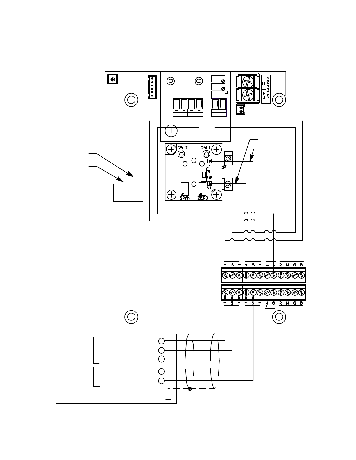
8. Connect the wires to the applicable detector/transmitter terminal strip at th e contr oller as
shown in Figure 7. Refer to the controller operator’s manual and the controller detector head
specification sheet for the 35-3001A-09 for detector/terminal strip connections specific to the
controller.
White (+)
Black (- )
Oxygen
Sensor
TOXIC
OXY
S
SIG/P WR
AM P 2
Red (+)
Blue (S)
OXYAMP 1
LEL/IR
Controller or Recording Device
+ 24 V DC
Oxygen
4/20 Signal
- (DC Ground)
+ 24 V DC
H2S
12 • 35-3001A-09 Oxygen/Hydrog en Sulfide Sample- Draw Detector
4/20 Signal
Figure 7: Wiring the Sample-Draw Detector to a Controller
AM P 1
AM P 2
OXY
LEL/IR
Page 17

Start Up
9. If shielded cable is used, connect the cable’s drain wire to an available chassis (earth) ground at
the controller. RKI controllers typically have a ground stud that can be used to ground the
cable’s drain wire.
This section describes procedures to start up the sample-draw detector and place the sample-draw
detector into normal operation.
Introducing Incoming Power
1. Complete the installation procedures described earlier in this m anual.
2. Verify that the wiring is correct and secure. Refer to the controller operator’s manual for
connections at the controller.
3. Turn on or plug in the power to the controller, then turn on the controll er.
4. Verify that the sample-draw detector’s Pilot LED is on.
5. Verify that the controller is on and operating properly. Refer to the controller operator’s
manual.
6. Verify that the flowmeter indicates a flow rate of approximately 1.0 SCFH. If necessary, use
the sensor flow control valve to adjust the flow rate. Turn the valve’s knob clockwise to
increase the flow and counterclockwise to decrease the flow.
NOTE: The following step tests for leaks in the sample line. This test will cause a low flow
condition at the sample-draw detector and a fail condition at the controller. Be sure to put
the controller into its calibration program or disable external alarms before performing
this test.
7. Verify that the incoming sample line is not leaking. To test the sample line, press and hold the
reset switch and plug the open end of the sample line with your thumb. If the flowmeter ball
drops to the bottom of the flowmeter, the incoming sample line is not leaking.
8. Remove your thumb from the sample line, release the reset switch, and verify the flowmeter
returns to a normal flow rate.
9. Enable alarms or place the controller in normal operation.
CAUTION: Allow the sample-draw detector to warm up for 5 minutes before you continue with
the next section, “Setting the Zero Reading.”
Setting the Zero Reading
CAUTION: If you suspect the presence of hydro gen sulfide or an abnormal oxygen concentration
in the monitoring environment, use the calibration kit and the zero air calibration
cylinder to introduce “fresh air” to the sensor and verify an accurate zero setting.
See “Calibration, Oxygen Sensor” on page 21 and “Calibration, H
page 22 for instructions on using a zero air calibration cylinder for setting the zero
reading.
S Sensor” on
2
1. Verify that the sample-draw detector is sampling a fresh air environmen t (env iron ment known
to be free of toxic gas and of normal oxygen concentration, 20.9%).
2. Open the housing door.
35-3001A-09 Oxygen/Hydrogen Sulfide Sample-Draw Detector • 13
Page 18

3. Set a voltmeter to measure in the millivolt (mV) range.
4. Plug the voltmeter leads into the test points on the oxygen amplifier. Plug the positive lead into
the red (+) test point; plug the negative lead into the black (-) test point.
5. Verify a voltmeter reading of 434 mV (± 2 mV).
6. If necessary, use a small flat-blade screwdriver to adjust the span potentiometer until the
voltmeter reading is 434 mV (± 2 mV).
7. Remove the voltmeter leads from the oxygen amplifier’s test points.
8. Plug the voltmeter leads into the test points on the H
9. Verify a voltmeter reading of 100 mV (± 2 mV).
10. If necessary, use a small flat-blade screwdriver to adjust the zero potentiometer until the
11. Remove the voltmeter leads from the H
12. Close the housing door.
Maintenance
This section describes maintenance procedures. It includes preventive maintenance procedures.
This section also includes procedures to troubleshoot the sample-draw detector, replace
components of the sample-draw detector, and adjust the low flow setting.
Preventive Maintenance
This section describes a preventive maintenance schedule to ensure the optimum performance of
the sample-draw detector. It includes daily, monthly, and qu arterly procedures.
Daily Visual Checks
1. Verify that the Pilot LED is on.
2. Verify that the flowmeter indicates a flow rate of approximately 1.0 SCFH. If necessary use the
3. Verify a display reading of 20.9% for the oxygen channel and 0 ppm for the H
Monthly Response Test
S amplifier. Plug the positive lead into the
2
red (+) test point; plug the negative lead into the black (-) test point.
voltmeter reading is 100 mV (± 2 mV).
S amplifier’s test points.
2
sensor flow control valve to adjust the fl ow rate to 1.0 SCFH. Turn the valve’s knob clockwis e
to increase the flow and counterclockwise to decrease the flow.
S channel at the
2
controller. Investigate significant changes in the display reading.
This procedure describes a test to verify that the sample-draw detector responds properly to the
target gas.
NOTE: To reduce the response time of this test, use a short incoming sample line. If the sample-
draw detector’s sample line is long, connect a shorter line for this test. Make sure you
reconnect the sample line after you complete this procedure.
NOTE: Performing a response test on the sample-draw detector may cause alarms. Be sure to put
the controller into its calibration program or disable external alarms before performing
this test.
14 • 35-3001A-09 Oxygen/Hydrog en Sulfide Sample- Draw Detector
Page 19

Preparing for the response test
NOTE: This procedure describes the RKI calibration kit that includes a demand flow re gulator.
1. Verify that the display reading at t h e controller is 20.9% for the oxygen channel and 0 ppm fo r
the H
S channel.
2
If the display reading is not 20.9% for the oxygen channel or 0 ppm for the H2S channel, set
the zero reading as described in “Calibration, Oxygen Sen sor” on page 21 or “Calibration, H
2
Sensor” on page 2 2, then cont inue th is procedure.
2. Set a voltmeter to measure in the millivolt (mV) range.
S
3. Open the housing door, then plug the voltmeter leads into the test points on the H
S amplifier.
2
Plug the positive lead into the red (+) test point; plug the negative lead into the black (-) test
point.
4. Use the following formula to determine the correct test points output for the test sample.
Output (mV) = (calibrating sample/fullscale) X 400 + 100
For example, with a test sample of 25 ppm and a fullscale setting of 100 ppm, the correct
output is 200 mV.
200 (mV) = (25/100) X 400 +100
Performing the response test
1. Screw the demand flow regulator into the hydrogen sulfide calibration cylinder.
2. Connect the calibration tubing from the demand flow regulator to the inlet fi tting. Gas will
begin to flow.
3. After approximately one minute, verify that the millivolt output at the hydrogen sulfide
amplifier stabilizes within ± 20% of the reading determined above. If the reading is not within
± 20% of the determined value, calibrate the sample-draw detector as described in
“Calibration, H
S Sensor” on page 2 2.
2
NOTE: If an H2S cylinder with a balance of nitr ogen is used, the oxygen r eading should decrease
to 0% or very close to 0%. If i t does, y ou do n ot need t o perfor m the breat hing tes t in st ep
7.
4. Remove the calibration tubing from the inlet fitting.
5. Store the calibration kit in a safe place.
6. Remove the voltmeter leads from the H
S amplifier and plug them into the oxygen amplifier.
2
Plug the positive lead into the red (+) test point; plug the negative lead into the black (-) test
point.
7. Exhale into the sample-draw detector’s inlet fitting.
8. Stop exhalin g into the sample line, th en verify that the millivolt reading decreased.
9. If the reading does not decrease, calibrate the sample draw detector as described in
“Calibration, Oxygen Sensor” on page 21.
10. Remove the voltmeter leads from the oxygen amplifier.
11. Close the housing door.
35-3001A-09 Oxygen/Hydrogen Sulfide Sample-Draw Detector • 15
Page 20

12. Reconnect the sample tubing to the inlet fitting.
Quarterly Calibration
Calibrate the sample-draw detector as described in “Calibration, Oxygen Sensor” on page 21 and
“Calibration, H
S Sensor” on page 2 2.
2
Troubleshooting
The troubleshooting guide describes symptoms, probable causes, and recommended action for
problems you may encounter with the sample-draw detector.
NOTE: This troubleshooting guide describes sample-draw detector problems only. See the
controller Operator’s Manual if the control ler exhibits any problems.
Fail Condition
Symptoms
• The sample-draw detector’s Fail LED is on.
• The monitoring device is operating properly but indicates a reading well below zero.
Probable causes
• The sample-draw detector’s flow rate is too low because of an obstructed sample line, failed
pump, etc.
• The sample-draw detector is malfunctioning.
• The sensor wiring is disconnected or misconnected.
Recommended action
1. At the sample-draw detector, set the correct flow rate with the sensor flow control val ve.
2. If you cannot set the correct flow rate, check the sample lines for obstructions or kinks.
3. Verify that the sensor wiring is correct and secure. “Wiring the Sample-Draw Detector to a
Controller” on page 11 describes sensor wiring connections.
4. Calibrate the sample-draw detector as described in “Calibration, Oxygen Se nsor” on page 21
and “Calibration, H
S Sensor” on page 22.
2
5. If the fail condition continues, replace the sensor( s) as describ ed in “Replacing Components o f
the Sample-Draw Detector” on page 17.
6. If the fail condition continues, contact R KI Instruments, Inc. for further instruction.
Slow or No Response/Difficult or Unable to Calibrate
Symptoms
• The sensor responds slowly or does not respond during the monthly response test.
• Unable to accurately set the zero or response reading during the calibration procedure.
• The sensor requires fre quent calibration.
Probable causes
• The calibration cylinder is low, out-dated, or defective.
• If a demand flow regulator cal ibra tion kit i s used, t he deman d flow r egulator is not functi oning
properly.
• The sample-draw detector’s flow rate is too low because of an obstructed sample line, failed
pump, etc.
16 • 35-3001A-09 Oxygen/Hydrog en Sulfide Sample- Draw Detector
Page 21

• The sample-draw detector is malfunctioning.
Recommended action
1. Verify that the calibration cylinder contains an adequate supply of a fresh test sample.
2. If a demand flow regulator calibration kit is used, use a different demand flow regulator to
determine if the original one is functioning properly.
3. If necessary, set the correct flow rate with the sensor flow control valve.
4. If you cannot set the correct flow rate, check the sample line for obstructions or kinks.
5. If the calibration/response difficulties continue, replace the sensor as described later in this
section.
6. If the calibration/response difficulties continue, contact RKI Instruments, Inc. for further
instruction.
Replacing Components of the Sample-Draw Detector
This section includes procedures to replace the oxygen sensor, H2S sensor, oxygen amplifier, H2S
amplifier, hydrophobic filter, and particle f ilter.
Replacing the Oxygen Sensor
1. Turn off the controller.
2. Turn off power to the controller.
3. Open the housing door of the sample-draw detector.
4. Loosen the two screws on the oxygen terminal strip and remove the lugs and wires from the
terminal strip.
5. Unscrew and remove the two screws that secure t he sensor retaining plate, then lift the plate
and sensor out of the flow block.
There is a gasket at the bottom of the flow block. Be sure the gas ket stays in place.
6. Place the replacement sensor in the oxygen flow block, then position the retaining plate on the
two standoffs.
7. Secure the retaining plate to the standoffs with the two screws you removed in step 4.
8. Guide the wires and lugs of the replacement sens or to the o xygen terminal s trip and ins ert each
lug into the appropriate terminal. See Figure 7 on page 12 for wiring connections. Tighten the
screws on the terminal strip.
9. Close and latch the housing door.
10. Turn on power to the controller.
11. Turn on the controller.
CAUTION: Allow the replacement sensor to warm up for 5 minutes before you continue.
12. Calibrate the replacement sensor as described in “Calibration, Oxygen Sensor” on page 21.
Replacing the H
S Sensor
2
1. Turn off the controller.
2. Turn off power to the controller.
3. Open the housing door of the sample-draw detector.
4. Unscrew and remove the two screws that secure t he H
35-3001A-09 Oxygen/Hydrogen Sulfide Sample-Draw Detector • 17
S amplifier, then lift the H2S amplifier
2
Page 22

and sensor off of the flow block.
There is a gasket at the bottom of the flow block. Be sure the gas ket stays in place.
5. Unplug the sensor from the H
6. Verify that you are using the correct replacement sensor, then plug the sensor into the H
S amplifier.
2
S
2
amplifier.
7. Place the sensor and amplifier in the H
8. Secure the H
S amplifier on the flow block with the two screws you removed in step 4.
2
S sensor cavity.
2
9. Close and latch the housing door.
10. Turn on power to the controller.
11. Turn on the controller.
CAUTION: Allow the replacement sensor to warm up for 5 minutes before you continue.
12. Calibrate the replacement sensor as described in “Calibration, H
S Sensor” on page 22.
2
Replacing the Oxygen Amplifier
1. Turn off the controller.
2. Turn off power to the controller.
3. Open the housing door of the sample-draw detector.
4. Remove the detector and controller plug-in terminal strips by grasping t he sides of the strips
with your fingers. Let the terminal strips hang by their connected wires while you replace the
amplifier.
5. Unscrew the screw in the lower left corner of the amplifier and remove the screw , lock washer ,
and flat washer. Be careful not to lose any of these parts.
6. Remove th e old amplifier from the main circu it board.
7. Install the new amplifier in the same orientation as the old amplifier. See Figure 1.
8. Reinstall the screw, lock washer, and flat washer you removed in step 5.
9. Install the detector and controller plug-in terminals strips into their sockets on the new
amplifier. If controller leads or detector cable leads were removed from the plug-in terminal
strips during this procedure, refer to Table 2 and Table 3 below.
Table 2:Reconnecting the Amplifier to the Amp 1 Terminals
on the Detector/Amp Terminal Strip
Amplifier Controller
Terminal Strip
SIG/PWR “S” AMP 1 “S”
SIG/PWR “+” AMP 1 “+”
Detector/Amp Terminal
Strip on Main PCB
18 • 35-3001A-09 Oxygen/Hydrog en Sulfide Sample- Draw Detector
Page 23

Table 3:Reconnecting the Amplifier to the Oxy Terminals
on the Detector/Amp Terminal Strip
Amplifier Detector
T erminal Strip
OXY “+” OXY “+”
OXY “-” OXY “-”
Detector/Amp Terminal
Strip on Main PCB
NOTE: When the sample-draw detector is first powered up with a new amplifier, the initial
output may be either high or be low zero depend in g on the set ting o f the span po t. Be s ure
to make arrangements so that this does not cause unwanted alarms.
10. Turn on power to the controller.
11. Turn on the controller and place it into normal operation.
12. Allow the sample-draw detector to warmup for 5 minutes.
13. Calibrate the oxygen channel as described in “Calibration, Oxygen Sensor” on page 21 of this
manual.
Replacing the H
S Amplifier
2
1. Turn off the controller.
2. Turn off power to the controller.
3. Open the housing door of the sample-draw detector.
4. Disconnect the red and blue wires coming fro m the H
S amplifier from the AMP 2 position on
2
the detector/amp terminal strip.
5. Unscrew the two screws in the upper right and lower left corners of the H
lift the H
6. Disconnect the sensor fr om the H
7. Plug the H
8. Place the sensor and amplifier in the H
9. Secure the H
10. Reconnect the wires coming from the H
S amplifier a nd sensor off of the flow block.
2
S amplifier.
2
S sensor into the new H2S amplifier.
2
S sensor cavity.
2
S amplifier on the flow block with the two screws you removed in step 5.
2
S amplifier to the AMP 2 position on the detector/
2
S flow block then
2
amp terminal strip.
Connect the red wire to the “+” terminal. Connect the blue wire to the “S” terminal.
NOTE: When the sample-draw detector is first powered up with a new amplifier, the initial
output may be either high or be low zero depend in g on the set ting o f the span po t. Be s ure
to make arrangements so that this does not cause unwanted alarms.
11. Turn on power to the controller.
12. Turn on the controller and place it into normal operation.
13. Allow the sample-draw detector to warmup for 5 minutes.
14. Calibrate the hydrogen sulfide channel as described in “Calibration, H
of this manual.
35-3001A-09 Oxygen/Hydrogen Sulfide Sample-Draw Detector • 19
S Sensor” on page 22
2
Page 24

Replacing the Hydrophobic Filter
1. Open the housing door of the sample-draw detector.
2. Disconnect the filter from the rubber elbows on each end of the filter, then remove the filter
from the sample-draw detector.
3. Install the new filter. Be sure the side of the filter marked “INLET” is connected to the elbow
that is connected to the inlet fitting.
4. Verify that the flow rate is approximately 1.0 SCFH, then close the housing door.
Replacing the Particle Filter
1. Disconnect the tubing routed to the sampling area, if installed, from the particle filter.
2. Disconnect the particle filter from the inlet fitting’s tubing stub.
3. Install the new particle filter onto the inlet fitting’s tubing stub. Be sure the arrow on the
particle filter is pointing toward the inlet fitting.
4. Reinstall the tubing routed to the sampling area.
Adjusting the Low Flow Setting
NOTE: Adjusting the low flow setting will cause a low flow alarm at the sample-draw detector
and a fail alarm at the controller. Be sure to put the controller into its calibration program
or disable external alarms before performing this test.
The factory-set low flow setting is 0.6 SCFH (±0.1). To adjust the low flow setting:
1. Use the sensor flow control valve to set the flow to 0.6 SCFH. Turn the valve’s knob clockwise
to increase the flow and counterclockwise to decrease the flow.
If the sample-draw detector goes into low flow alarm before you can adjust the flow down to
0.6 SCFH, adjust the pressure switch adjustment screw 1/4 turn clockwise, then attempt to set
the flow again. Repeat this step until you are able to adjust the flow to 0.6 SCFH.
NOTE: The pressure switch adjustment screw is accessible through a circular cutout in the
flowmeter circuit board.
2. Slowly turn the pressure switch adjustment screw counterclockwise just until the sample-draw
detector goes into low flow alarm.
3. Turn the sensor flow control valve’s knob clockwise to increase the flow until the unit is out of
low flow alarm.
4. Decrease the flow very slowly by turning the sensor flow co nt rol valve’s knob
counterclockwise and verify that the low flow alarm is 0.6 SCFH (±0.1).
If the low flow alarm is set too low, turn the pressure switch adjustment screw slightly
clockwise. Repeat steps 3 and 4 if necessary.
5. Use the sensor flow control valve to set the flow to 1.0 SCFH.
6. Make sure the sample-draw detector’s Fail LED is off.
20 • 35-3001A-09 Oxygen/Hydrog en Sulfide Sample- Draw Detector
Page 25

Calibration Frequency
Although there is no particular calibration frequency that is correct for all applications, a calibration
frequency of every 3 months is adequate for most sample draw detector applications. Unless
experience in a particular application dictates otherwise, RKI Instruments, Inc. recommends a
calibrat ion freque ncy of every 3 months.
If an application is not very demanding, for example detection in a clean, temperature controlled
environment, and calibration adjustments are minimal at calibration, then a calibration frequency of
every 6 months is adequate.
If an application is very demanding, for example if the environment is not well controlled, then
more frequent calibration than every 3 months may be necessary.
Calibration, Oxygen Sensor
This section describes how to calibrate the oxygen s ens or in the s ample-draw detector. It includes
procedures to prepare for calibration, set the fresh air reading, set the zero reading, and return to
normal operation.
NOTE: Calibrating the sample draw detector may cause alarms. Be sure to put the controller into
its calibration program or disable external alarms before continuing.
NOTE: This procedure describes calibration using a demand flow regulator.
Prepari ng for Ca libration
NOTE: If you can verify a fresh air environment, it is not necessary to use a zero air calibrating
sample to set the fresh air reading at the controller.
1. Follow the instructions in the controller’s operator’s manual for entering calibration mode.
2. Screw the regulator into the zero air calibration cylinder.
3. Open the housing door.
4. Set a voltmeter to measure in the millivolt (mV) range and plug the leads into the oxygen
amplifier.
Plug the positive lead into the red (+) amplifier test point; plug the negative lead into the black
(-) amplifier test point.
Setting the Fresh Air Reading
1. Connect the sample tubing from the demand flow regulator to the sample-draw detector’s inlet
fitting. This step is not necessary if you verified a fresh air environment earlier in this
procedure.
2. Allow the sample draw detector to draw sample for one minute.
3. Verify a voltmeter reading of 434 mV (± 2 mV).
4. If necessary, use a small flat-blade screwdriver to adjust the span potentiometer until the
voltmeter reading is 434 mV (± 2 mV). If you used a zero air calibration cylinder to set the
zero reading, proceed to step 5. If you verified a fresh air environment, proceed to the next
35-3001A-09 Oxygen/Hydrogen Sulfide Sample-Draw Detector • 21
Page 26

section, Setting the Zero Reading.
5. Disconnect the sample tubing from the inlet fitting.
6. Unscrew the regulator from the zero air calibration cylinder.
Setting the Zero Reading
1. Screw the demand flow regul ator onto the 100% N2 calibration cylinder.
NOTE: If you do not want to keep two calibration cylinders, 100% N2 and 25 ppm H2S in
nitrogen, you may use the 25 ppm H2S in nitrogen to zero the oxygen sensor.
2. Connect the sample tubing from the regulator to the inlet line.
3. Allow the sample-draw detector to draw the calibrating sample for 1 minute.
4. Verify a voltmeter reading of 100 mV (± 2 mV).
5. If necessary, use the zer o potentiometer on the amplifier to adjust the reading to 100 mV (± 2
mV).
6. Disconnect the sample tubing from the sample-draw detector’s inlet fitting.
7. Reconnect the incoming sample line to the inlet fitting.
8. Unscrew the regulator from the calibration cylinder.
Returning to Normal Operation
1. Wait 1 to 2 minutes to allow the oxygen reading at the controller to return to normal, then
return the controller to normal operation.
NOTE: If you do not allow the oxygen reading to return to normal, then unwanted alarms may
occur.
2. Remove the voltmeter leads from the amplifier test points.
3. Close the housing door.
4. Verify that the controller display reading stabili zes at 20.9% .
5. Store the components of the calibration kit in a safe and convenient place.
Calibration, H2S Sensor
This section describes how to calibrate the hydrogen sulfide sensor of the sample-dra w detector. It
includes procedures to prepare for calibration, set the zero reading, set the response reading, and
return to normal operation.
NOTE: This procedure describes calibration using a demand flow regulator.
Prepari ng for Ca libration
1. Follow the instructions in the controller’s operator’s manual for entering calibration mode.
NOTE: If you can verify a fresh air environment, it is not necessary to us e the zero air calib ration
cylinder to set the zero reading.
22 • 35-3001A-09 Oxygen/Hydrog en Sulfide Sample- Draw Detector
Page 27

2. Screw the regulator into a zero air calibration cylinder.
3. Set a voltmeter to measure in the millivolt (mV) range and plug the leads into the H
amplifier.
Plug the positive lead into the red (+) amplifier test point; plug the negative lead into the black
(-) amplifier test point.
4. Use the following formula to determine the correct test points output for the test
sample.
Output (mV) = (calibrating sample/fullscale) X 400 + 100
For example, with a test sample of 25 ppm and a fullscale setting of 100 ppm, the
correct output is 200 mV.
200 (mV) = (25/100) X 400 +100
S
2
Setting the Zero Reading
1. Connect the sample tubing from the demand flow regulator to the sample-draw detector’s inlet
line. This step is not necessary if you verified a fresh air environment earlier in this
procedure.
2. Allow the sample-draw detector to draw sample for one minute.
3. Verify a voltmeter reading of 100 mV (± 2 mV).
4. If necessary, use a small flat-blade screwdriver to adjust the zero potentiometer until the
voltmeter reading is 100 mV (± 2 mV). If you used a zero air calibration cylinder to set the
zero reading, proceed to step 5. If you verified a fresh air environment, proceed to the next
section, Setting the Response Reading.
5. Disconnect the sample tubing from the inlet line.
6. Unscrew the regulator from the zero air calibration cylinder.
Setting the Response Reading
1. Screw the regulator into the hydrogen sulfide calibration cylinder.
2. Connect the sample tubing from the demand flow regulator to the sample-draw detector’s inlet
line.
3. Allow the sample-draw detector to draw sample for one minute.
4. When the reading on the voltmeter stabilizes, verify that the reading matches the response
reading (±2 mV) you determined earlier.
5. If necessary, use the span potentiometer on the amplifier to adjust the reading to match the
correct response reading.
6. Disconnect the sample tubing from the inlet line.
7. Unscrew the regulator from the hydrogen sulfide calibration cylinder.
Returning to Normal Operation
1. Wait ap pro ximately one minute to allow the hydrogen sulfide reading to stabilize.
2. Remove the voltmeter leads from the amplifier test points.
3. Close the housing door.
4. Follow the instructions in the controller’s operator’s manual to exit the calibration mode.
5. Store the components of the calibration kit in a safe and convenient place.
35-3001A-09 Oxygen/Hydrogen Sulfide Sample-Draw Detector • 23
Page 28

Parts List
Part Number Description
06-1248RK Sample tubing, 3/16 x 5/16, specify length
06-1248RK-03 Sample tubing, 3/16 in. x 5/16 in., 3 feet (for calibration kit)
Table 2 lists replacement parts and accessories for the sample-draw detector.
Table 4: Parts List
07-0053RK Gasket for oxygen and H
S sensor flow blocks
2
30-1016RK Pump
33-0165RK Hydrophobic filter
33-0167RK Particle filter
57-0140RK H
S amplifier
2
57-1064RK-11 Oxygen amplifier
71-0311RK Operator’s Manual, 35-3001A-09 Sample-Draw Detector
81-0076RK-01 Zero air calibra tion cylinder, 34 liter
81-0076RK-03 Zero air calibration cylinder, 103 liter
81-0078RK-01 Calibration cylinder, 100% nitrogen, 34 liter
81-0078RK-03 Calibration cylinder, 100% nitrogen, 103 liter
81-0151RK-04 Calibration cylinder, 25 ppm H
S in nitrogen, 34 liter aluminum
2
81-1054RK Regulator, demand flow, for 58- and 103-liter aluminum or steel calibration
cylinders and 34-liter aluminum cylinders
81-1055RK Regulator, demand flow, for 17 and 34 liter steel calibration cylinders
ES-1537-H2S Hydrogen sulfide sensor
OS-B11 Oxygen sensor
24 • 35-3001A-09 Oxygen/Hydrog en Sulfide Sample- Draw Detector
 Loading...