

RKI Instruments 35-3001A-07, 35-3001-06-01 Operator's Manual

35-3001A-07
Combustible Gas/Hydrogen Sulfide
Sample-Draw Detector
Operator’s Manual
Part Number: 71-0431
Revision: 0
Released: 8/7/17
www.rkiinstruments.com

WARNING
Read and understand this instruction manual before operating
detector. Improper use of the detector could result in bodily harm
or death.
Periodic calibration and maintenance of the detector is essential
for proper operation and correct readings. Please calibrate and
maintain this detector regularly! Frequency of calibration
depends upon the type of use you have and the sensor types.
Typical calibration frequencies for most applications are between
3 and 6 months, but can be required more often or less often
based on your usage.
35-3001A-07 Combustible Gas/Hydrogen Sulfide Sample-Draw Detector

Product Warranty
RKI Instruments, Inc. warrants gas alarm equipment sold by us to be free from defects in materials,
workmanship, and performance for a period of one year from date of shipment from RKI
Instruments, Inc. Any parts found defective within that period will be repaired or replaced, at our
option, free of charge. This warranty does not apply to those items which by their nature are subject
to deterioration or consumption in normal service, and which must be cleaned, repaired, or replaced
on a routine basis. Examples of such items are:
Warranty is voided by abuse including mechanical damage, alteration, rough handling, or repair
procedures not in accordance with the operator’s manual. This warranty indicates the full extent of
our liability, and we are not responsible for removal or replacement costs, local repair costs,
transportation costs, or contingent expenses incurred without our prior approval.
THIS W ARRAN T Y IS EXPRESSLY IN LIEU OF ANY AND ALL OTHER
WARRANTIES AND REPRESENTATIONS, EXPRESSED OR IMPLIED, AND
ALL OTHER OBLIGATIONS OR LIABILITIES ON THE PART OF RKI
INSTRUMENTS, INC. INCLUDING BUT N OT LIMITED TO, THE WARRANTY
OF MERCHANTABILITY OR FITNESS FOR A PARTICULAR PURPOSE. IN
NO EVENT SHALL RKI INSTRUMENTS, INC. BE LIABLE FOR INDIRECT,
INCIDENTAL, OR CONSEQUENTIAL LOSS OR DAMAGE OF ANY KIND
CONNECTED WITH THE USE OF ITS PRODUCTS OR FAILURE OF ITS
PRODUCTS TO FUNCTION OR OPERATE PROPERLY.
a) Absorbent cartridges d) Batteries
b) Pump diaphragms and valves e) Filter elements
c) Fuses
This warranty covers instruments and parts sold to users by authorized distributors, dealers, and
representatives as appointed by RKI Instruments, Inc.
We do not assume indemnification for any accident or damage caused by the operation of this gas
monitor, and our warranty is limited to the replacement of parts or our complete goods.
35-3001A-07 Combustible Gas/Hydrogen Sulfide Sample-Draw Detector

Table of Contents
Overview . . . . . . . . . . . . . . . . . . . . . . . . . . . . . . . . . . . . . . . . . . . . . . . . . . . . . . . . . . . . . . . . . . . . 1
Specifications. . . . . . . . . . . . . . . . . . . . . . . . . . . . . . . . . . . . . . . . . . . . . . . . . . . . . . . . . . . . . . . . . 1
Description. . . . . . . . . . . . . . . . . . . . . . . . . . . . . . . . . . . . . . . . . . . . . . . . . . . . . . . . . . . . . . . . . . . 2
External Components. . . . . . . . . . . . . . . . . . . . . . . . . . . . . . . . . . . . . . . . . . . . . . . . . . . . . . . . . . . . . . . . . . . . 3
Internal Components . . . . . . . . . . . . . . . . . . . . . . . . . . . . . . . . . . . . . . . . . . . . . . . . . . . . . . . . . . . . . . . . . . . . 5
Installation. . . . . . . . . . . . . . . . . . . . . . . . . . . . . . . . . . . . . . . . . . . . . . . . . . . . . . . . . . . . . . . . . . . 8
Mounting the Sample-Draw Detector . . . . . . . . . . . . . . . . . . . . . . . . . . . . . . . . . . . . . . . . . . . . . . . . . . . . . . . 8
Connecting the Sample Lines to the Sample-Draw Detector . . . . . . . . . . . . . . . . . . . . . . . . . . . . . . . . . . . . . 9
Wiring the Sample-Draw Detector to a Controller . . . . . . . . . . . . . . . . . . . . . . . . . . . . . . . . . . . . . . . . . . . . 10
Start Up . . . . . . . . . . . . . . . . . . . . . . . . . . . . . . . . . . . . . . . . . . . . . . . . . . . . . . . . . . . . . . . . . . . . 12
Introducing Incoming Power. . . . . . . . . . . . . . . . . . . . . . . . . . . . . . . . . . . . . . . . . . . . . . . . . . . . . . . . . . . . . 12
Setting the Zero Reading . . . . . . . . . . . . . . . . . . . . . . . . . . . . . . . . . . . . . . . . . . . . . . . . . . . . . . . . . . . . . . . . 12
Maintenance . . . . . . . . . . . . . . . . . . . . . . . . . . . . . . . . . . . . . . . . . . . . . . . . . . . . . . . . . . . . . . . . 13
Preventive Maintenance. . . . . . . . . . . . . . . . . . . . . . . . . . . . . . . . . . . . . . . . . . . . . . . . . . . . . . . . . . . . . . . . . 13
Troubleshooting. . . . . . . . . . . . . . . . . . . . . . . . . . . . . . . . . . . . . . . . . . . . . . . . . . . . . . . . . . . . . . . . . . . . . . . 15
Replacing Components of the Sample-Draw Detector . . . . . . . . . . . . . . . . . . . . . . . . . . . . . . . . . . . . . . . . . 16
Adjusting the Low Flow Setting . . . . . . . . . . . . . . . . . . . . . . . . . . . . . . . . . . . . . . . . . . . . . . . . . . . . . . . . . . 19
Removing the Particle Filter’s Tubing Stub, if Necessary . . . . . . . . . . . . . . . . . . . . . . . . . . . . . . . . . . . . . . 20
Calibration Frequency . . . . . . . . . . . . . . . . . . . . . . . . . . . . . . . . . . . . . . . . . . . . . . . . . . . . . . . . 21
Calibration, LEL Sensor . . . . . . . . . . . . . . . . . . . . . . . . . . . . . . . . . . . . . . . . . . . . . . . . . . . . . . 21
Preparing for Calibration. . . . . . . . . . . . . . . . . . . . . . . . . . . . . . . . . . . . . . . . . . . . . . . . . . . . . . . . . . . . . . . . 21
Setting the Zero Reading . . . . . . . . . . . . . . . . . . . . . . . . . . . . . . . . . . . . . . . . . . . . . . . . . . . . . . . . . . . . . . . . 22
Setting the Response Reading . . . . . . . . . . . . . . . . . . . . . . . . . . . . . . . . . . . . . . . . . . . . . . . . . . . . . . . . . . . . 22
Returning to Normal Operation. . . . . . . . . . . . . . . . . . . . . . . . . . . . . . . . . . . . . . . . . . . . . . . . . . . . . . . . . . . 22
Calibration, H2S Sensor . . . . . . . . . . . . . . . . . . . . . . . . . . . . . . . . . . . . . . . . . . . . . . . . . . . . . . . 23
Preparing for Calibration. . . . . . . . . . . . . . . . . . . . . . . . . . . . . . . . . . . . . . . . . . . . . . . . . . . . . . . . . . . . . . . . 23
Setting the Zero Reading . . . . . . . . . . . . . . . . . . . . . . . . . . . . . . . . . . . . . . . . . . . . . . . . . . . . . . . . . . . . . . . . 23
Setting the Response Reading . . . . . . . . . . . . . . . . . . . . . . . . . . . . . . . . . . . . . . . . . . . . . . . . . . . . . . . . . . . . 24
Returning to Normal Operation. . . . . . . . . . . . . . . . . . . . . . . . . . . . . . . . . . . . . . . . . . . . . . . . . . . . . . . . . . . 24
Parts List . . . . . . . . . . . . . . . . . . . . . . . . . . . . . . . . . . . . . . . . . . . . . . . . . . . . . . . . . . . . . . . . . . . 25
35-3001A-07 Combustible Gas/Hydrogen Sulfide Sample-Draw Detector
Overview
This operator’s manual describes the 35-3001A-07 combustible gas/hydrogen sulfide sample-draw
detector. This manual also describes how to install, start up, maintain, and calibrate the sampledraw detector when using it with a gas monitoring controller. A parts list at the end of this manual
lists replacement parts and accessories for the sample-draw detector.
Specifications
Table 1 lists specifications for the combustible gas/hydrogen sulfide sample-draw detector. See the
controller Operator’s Manual for information specific to the controller.
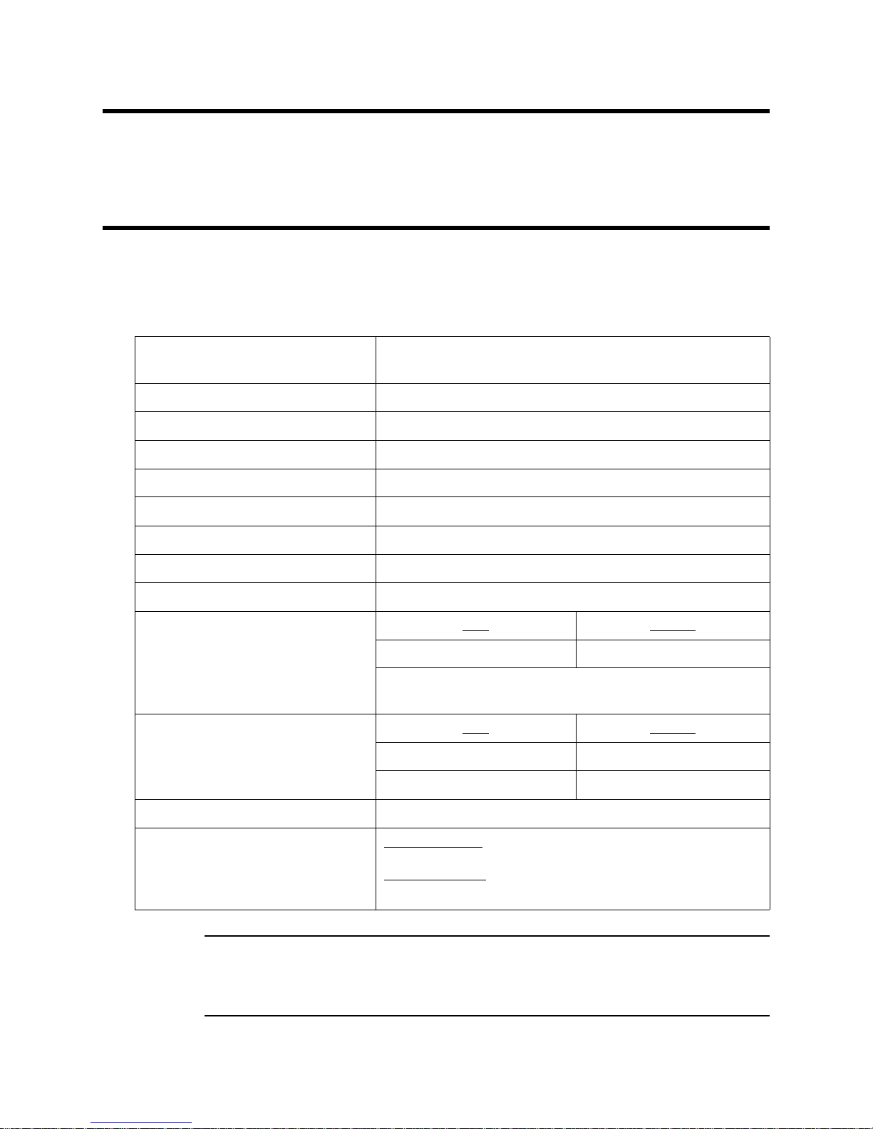
Table 1: Specifications
Target Gases and Detection Range Combustible Gas: 0 - 100% LEL
Hydrogen Sulfide: 0 - 100 ppm
Input Power 24 VDC Nominal (18.5 VDC - 30 VDC)
Construction (housing) Fiberglass/polyester (NEMA 4X)
Dimensions 8.5 in. H x 6.5 in. W x 4.25 in. D
Weight 4.5 lbs.
Sampling Method Sample-draw
Sample Flow 3.0 SCFH typical, with no inlet or exhaust line
Flow to Sensor 1.0 SCFH (nominal)
Low Flow Setpoint 0.6 ± 0.1 SCFH
Maximum Recommended Inlet/
Exhaust Line Length for
1/4” O.D. x 1/8” I.D. Tubing
* RKI Instruments, Inc. does not recommend installing this tubing
size on both the inlet and exhaust.
Maximum Recommended Inlet/
Exhaust Line Length for
1/4” O.D. x 0.170” I.D. Tubing
Response Time 90% in 30 seconds
Accuracy Combustible Gas
± 5% of reading or ± 2% LEL (whichever is greater)
Hydrogen Sulfide
± 5% of reading or ± 2 ppm H
Inlet
50 feet 0 feet
Inlet
50 feet 50 feet
75 feet 0 feet
:
:
S (whichever is greater)
2
Exhaust
Exhaust
WARNING: When using the 35-3001A-07, you must follow the instr uctions and warnings in
35-3001A-07 Com bustib le Gas /Hy drogen Sulfid e Sample-Draw Detec tor • 1
this manual to assure proper and safe operation of the 35-3001A-07 and to
minimize the risk of personal injury. Be sure to maintain and periodically
calibrate t he 35-3001A- 07 as describe d in this manual.
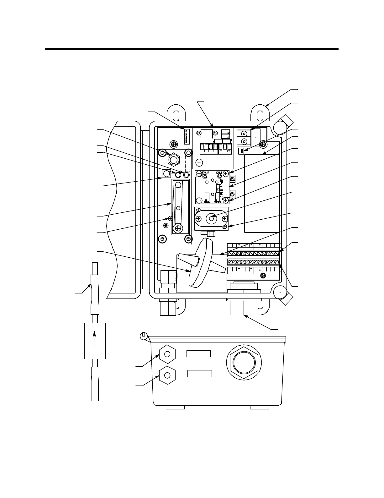
Description
Mounting
Foot, 4X
B
_
LEL Am plifier
Pump
H2S S ensor
(inside bl ock)
Pump Connector
W
LEL
GBR
W
+
O
X
Y
G
E
N
S
PWR/SIG
Flow B a ffle
LE L Flow
Block
LE L
Sensor
H2S Fl ow
Block
Se nsor
Current
148m A
Sensor Flow
Control Va lve
Pilot LED
Fail L ED
Flowmeter
Pum p Reset
Switch
S G B
AMP 1
+
AMP 2
+
WG
OXY
S
+
R
AMP OXY
AMP 2
Hydrophobic
Filter
This E n dTo
Inlet F itting
Particle Filter
Oxygen
Sensor
Terminal
Strip
Intercon nect
Terminal
Strip
LEL/ I R
FlowmeterCircui t
Board Connector
H2S
Amplifier
Inlet
Fitting
Exhaust
Fitting
LEL/ I R
W
3/4" Conduit Hu b
INLE T
EX HAUST
S
+
G B
Pressure Switch
Adjustm ent Screw
(be hind PCB)
Detector/A mp
Terminal Strip
(Factory Wired)
W
+
S R
+
This section describes the components of the combustible gas/hydrogen sulfide sample-draw
detector.
Figure 1: Combustible Gas/Hydrogen Sulfide Sample-Draw Detector Component Location
2 • 35-3001A-07 Combustible Gas/Hydrogen Sulfide Sample-Draw Detector
External Components
Restrictor
Hydrogen
Sulfide
Sensor
LEL
Sensor
Pump
Flowmeter
Flow
Baffle
Particle Filter
Sensor Flow
Con tr o l Valve
Exhaust
Flowmeter PCB
Pressure Switch
Hydrophobic Filter
Inlet
This section describes the sample-draw detector’s external components.
Housing
The sample-draw detector’s fiberglass housing is weather- and corrosion-resistant. It is suitable for
installation where general purpose equipment is in use.
The housing door is hinged on the left side and is secured by two latches on the right side. The
flowmeter and status LEDs are visible through a window in the housing door.
Four mounting feet are attached to the back of the housing (one at each corner). Use the mounting
feet to install the housing to a vertical surface.
Sample Fittings
The sample fittings are located on the left side of the bottom of the housing. The inlet fitting is near
the front of the housing and the exhaust fitting is near the back of the housing. The sample fittings
accept 1/4 in. rigid tubing. See the Installation section on page 8 to connect tubing to the sample
fittings.
Particle Filter
A particle filter with a tubing stub on one end is shipped with the instrument but it is not factory
installed. If the particle filter is installed directly to the inlet fitting, the tubing stub must be used. If
the particle filter is installed somewhere else, like at the end of the inlet line, the tubing stub can be
used or removed.
Conduit Hub
One 3/4” conduit hub is located on the right side of the bottom of the housing. It is used for routing
wiring into the housing by using conduit or an appropriate cable bushing.
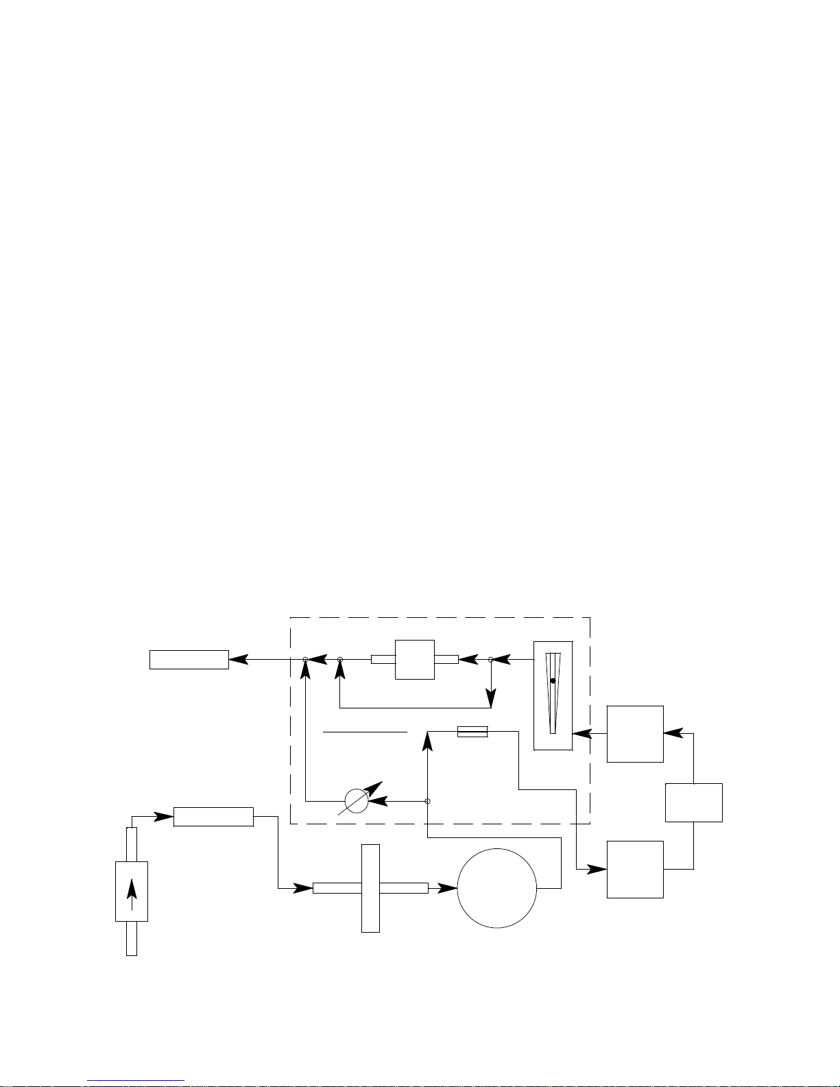
Internal Components
This section describes the sample-draw detector’s internal components (see Figure 1). Figure 2
illustrates how the gas sample moves through the flow system.
Figure 2: Combustible Gas/Hydrogen Sulfide Sample-Draw Detector Flow Diagram
35-3001A-07 Com bustib le Gas /Hy drogen Sulfid e Sample-Draw Detec tor • 3

Main Circuit Board
The main circuit board includes the detector/amp terminal strip, interconnect terminal strip, oxygen
sensor terminal strip, pump connector, and flowmeter circuit board connector (see Figure 1).
Detector/Amp Terminal Strip
The detector/amp terminal strip is the upper twelve-point terminal strip in the bottom right corner
of the main circuit board. Use the detector/amp terminal strip to connect the LEL amplifier and the
H
S amplifier to the main circuit board.
2
NOTE: The LEL amplifier and H2S amplifier are factory-wired to the main circuit board. See the
“Installation” section on page 8 for all wiring procedures related to the sample-draw
detector.
Interconnect Terminal Strip
The interconnect terminal strip is the lower twelve-point terminal strip in the bottom right corner of
the main circuit board. Use the interconnect terminal strip to connect the sample-draw detector to a
controller.
Oxygen Sensor Terminal Strip
The oxygen sensor terminal strip is a two-point terminal strip in the upper right corner of the main
circuit board. This terminal strip is not used in this version of the sample-draw detector.
Pump Connector
The pump connector is the two-point connector below the oxygen terminal strip in the upper right
corner of the main circuit board. Use the pump connector to connect the pump to the main circuit
board.
NOTE: The pump is factory-wired to the main circuit board. See “Installation” on page 8 for all
wiring procedures related to the sample-draw detector.
Flowmeter Circuit Board Co nnector
The flowmeter circuit board connector is a six-position connector in the upper left corner of the
main circuit board. Use the flowmeter circuit board connector to connect the flowmeter circuit
board to the main circuit board.
NOTE: The flowmeter circuit board is factory wired to the main circuit board. See “Installation”
on page 8 for all wiring procedures related to the sample-draw detector.
Flowmeter Circuit Board
The flowmeter circuit board is mounted to the left side of the main circuit board using standoffs. It
includes the flowmeter, sensor flow control valve, status LEDs, pressure switch, and pump reset
switch.
Flowmeter
The flowmeter is mounted to the right side of the flowmeter circuit board. You can see it through
the window in the door. A ball in the flowmeter column indicates the flow rate to the sensor. The
flowmeter measures the flow in the range 0.2 to 2.0 SCFH (Standard Cubic Feet per Hour). The
optimum flow rate is 1.0 SCFH.
4 • 35-3001A-07 Combustible Gas/Hydrogen Sulfide Sample-Draw Detector

Sensor Flow Control Valve
The sensor flow control valve is mounted to the flowmeter circuit board above the flowmeter. The
sensor flow control valve adjusts the flow rate to the detector. Turn the valve’s knob clockwise to
increase the flow and counterclockwise to decrease the flow.
Status LEDs
Two status LEDs are above the flowmeter. They are also visible through the window in the housing
door. The green Pilot LED is on when the sample-draw detector is receiving power from the
controller. The red Fail LED is on when the sample flow rate is below the low flow level.
Pressure Switch
The pressure switch is mounted to the back of the flowmeter circuit board. The pressure switch
monitors the flow rate of the incoming gas sample.
If the flow rate falls below the preset low flow level, the pressure switch causes the Fail LED to
turn on and interrupts the signal from the detector. The interrupted detector signal causes a fail
condition at the controller. The low flow level is factory-set at 0.6 SCFH (±0.1 SCFH). See
“Adjusting the Low Flow Setting” on page 19 to adjust this setting.
Pump Reset Switch
The pump reset switch is located to the left of the status LEDs. When a low flow condition occurs,
the pump will be shut off. To reset the low flow condition and start the pump again, press and hold
the pump reset switch for about 2 seconds, then release.
Hydrophobic Filter
The hydrophobic filter is located toward the bottom left of the main circuit board. The filter
prevents particulates and water in the incoming gas sample from damaging the flow and detection
systems. Replace the filter when it appears dirty, discolored, or clogged.
Pump
The pump is mounted to the right side of the main circuit board. The pump pulls the gas sample
into the sample-draw detector. The pump operates on 24 VAC, which is generated from the 24
VDC supplied by the controller.
Flow Baffle
A flow baffle is located at the bottom of the main circuit board, behind the hydrophobic filter. Its
function is to isolate the hydrogen sulfide sensor from vibrations in the flow line that are caused by
the pump.
Combustible Gas (LEL) Sensor
The catalytic combustible gas sensor detects combustible gas in the %LEL range. It uses a catalytic
element for detection. The reaction of gas with oxygen on the catalyst causes a change in the
resistance of the element which changes the current flowing through it. The current is proportional
to the detection range of the sample-draw detector.
The combustible gas sensor is installed in the flow block and the flow block is mounted to the
middle of the main circuit board. It is the lower of the two flow blocks mounted to the main circuit
board. The sensor housing includes a sintered metal flame arrestor on one end that allows gas to
diffuse into the sensor. On the other end, five pins extend from the sensor and plug into the socket
connector. The connector allows you to replace the sensor without disconnecting the wiring. Four
leads extending from the connector are factory wired to the amplifier.
35-3001A-07 Com bustib le Gas /Hy drogen Sulfid e Sample-Draw Detec tor • 5
 Loading...