

RKI Instruments 35-3001-05-03 Operator's Manual

35-3001-05-03
Carbon Dioxide Sample-Draw Detector
Operator’s Manual
Part Number: 71-0413
Revision: 0
Released: 8/4/17
www.rkiinstruments.com

WARNING
Read and understand this instruction manual before operating
detector. Improper use of the detector could result in bodily harm
or death.
Periodic calibration and maintenance of the detector is essential
for proper operation and correct readings. Please calibrate and
maintain this detector regularly! Frequency of calibration
depends upon the type of use you have and the sensor types.
Typical calibration frequencies for most applications are between
6 and 12 months, but can be required more often or less often
based on your usage.
35-3001-05-03 Carbon Dioxide Sample-Draw Detector

Product Warranty
RKI Instruments, Inc. warrants gas alarm equipment sold by us to be free from defects in materials,
workmanship, and performance for a period of one year from date of shipment from RKI
Instruments, Inc. Any parts found defective within that period will be repaired or replaced, at our
option, free of charge. This warranty does not apply to those items which by their nature are subject
to deterioration or consumption in normal service, and which must be cleaned, repaired, or replaced
on a routine basis. Examples of such items are:
Warranty is voided by abuse including mechanical damage, alteration, rough handling, or repair
procedures not in accordance with the operator’s manual. This warranty indicates the full extent of
our liability, and we are not responsible for removal or replacement costs, local repair costs,
transportation costs, or contingent expenses incurred without our prior approval.
THIS W ARRAN T Y IS EXPRESSLY IN LIEU OF ANY AND ALL OTHER
WARRANTIES AND REPRESENTATIONS, EXPRESSED OR IMPLIED, AND
ALL OTHER OBLIGATIONS OR LIABILITIES ON THE PART OF RKI
INSTRUMENTS, INC. INCLUDING BUT N OT LIMITED TO, THE WARRANTY
OF MERCHANTABILITY OR FITNESS FOR A PARTICULAR PURPOSE. IN
NO EVENT SHALL RKI INSTRUMENTS, INC. BE LIABLE FOR INDIRECT,
INCIDENTAL, OR CONSEQUENTIAL LOSS OR DAMAGE OF ANY KIND
CONNECTED WITH THE USE OF ITS PRODUCTS OR FAILURE OF ITS
PRODUCTS TO FUNCTION OR OPERATE PROPERLY.
a) Absorbent cartridges d) Batteries
b) Pump diaphragms and valves e) Filter elements
c) Fuses
This warranty covers instruments and parts sold to users by authorized distributors, dealers, and
representatives as appointed by RKI Instruments, Inc.
We do not assume indemnification for any accident or damage caused by the operation of this gas
monitor, and our warranty is limited to the replacement of parts or our complete goods.
35-3001-05-03 Carbon Dioxide Sample-Draw Detector

Table of Contents
Overview . . . . . . . . . . . . . . . . . . . . . . . . . . . . . . . . . . . . . . . . . . . . . . . . . . . . . . . . . . . . . . . . . . . . 1
Specifications. . . . . . . . . . . . . . . . . . . . . . . . . . . . . . . . . . . . . . . . . . . . . . . . . . . . . . . . . . . . . . . . . 1
Description. . . . . . . . . . . . . . . . . . . . . . . . . . . . . . . . . . . . . . . . . . . . . . . . . . . . . . . . . . . . . . . . . . . 2
External Components. . . . . . . . . . . . . . . . . . . . . . . . . . . . . . . . . . . . . . . . . . . . . . . . . . . . . . . . . . . . . . . . . . . . 3
Internal Components . . . . . . . . . . . . . . . . . . . . . . . . . . . . . . . . . . . . . . . . . . . . . . . . . . . . . . . . . . . . . . . . . . . . 5
Installation. . . . . . . . . . . . . . . . . . . . . . . . . . . . . . . . . . . . . . . . . . . . . . . . . . . . . . . . . . . . . . . . . . . 6
Mounting the Carbon Dioxide Sample-Draw Detector. . . . . . . . . . . . . . . . . . . . . . . . . . . . . . . . . . . . . . . . . . 6
Connecting the Sample Lines to the Sample-Draw Detector . . . . . . . . . . . . . . . . . . . . . . . . . . . . . . . . . . . . . 7
Wiring the Carbon Dioxide Sample-Draw Detector to a Controller . . . . . . . . . . . . . . . . . . . . . . . . . . . . . . . . 8
Start Up . . . . . . . . . . . . . . . . . . . . . . . . . . . . . . . . . . . . . . . . . . . . . . . . . . . . . . . . . . . . . . . . . . . . 10
Introducing Incoming Power. . . . . . . . . . . . . . . . . . . . . . . . . . . . . . . . . . . . . . . . . . . . . . . . . . . . . . . . . . . . . 10
Setting the Zero Reading . . . . . . . . . . . . . . . . . . . . . . . . . . . . . . . . . . . . . . . . . . . . . . . . . . . . . . . . . . . . . . . . 10
Maintenance . . . . . . . . . . . . . . . . . . . . . . . . . . . . . . . . . . . . . . . . . . . . . . . . . . . . . . . . . . . . . . . . 11
Preventive Maintenance. . . . . . . . . . . . . . . . . . . . . . . . . . . . . . . . . . . . . . . . . . . . . . . . . . . . . . . . . . . . . . . . . 11
Troubleshooting. . . . . . . . . . . . . . . . . . . . . . . . . . . . . . . . . . . . . . . . . . . . . . . . . . . . . . . . . . . . . . . . . . . . . . . 12
Replacing Components of the Carbon Dioxide Sample-Draw Detector. . . . . . . . . . . . . . . . . . . . . . . . . . . . 13
Adjusting the Low Flow Setting . . . . . . . . . . . . . . . . . . . . . . . . . . . . . . . . . . . . . . . . . . . . . . . . . . . . . . . . . . 14
Removing the Particle Filter’s Tubing Stub, if Necessary . . . . . . . . . . . . . . . . . . . . . . . . . . . . . . . . . . . . . . 15
Calibration Frequency . . . . . . . . . . . . . . . . . . . . . . . . . . . . . . . . . . . . . . . . . . . . . . . . . . . . . . . . 16
Calibration. . . . . . . . . . . . . . . . . . . . . . . . . . . . . . . . . . . . . . . . . . . . . . . . . . . . . . . . . . . . . . . . . . 16
Preparing for Calibration. . . . . . . . . . . . . . . . . . . . . . . . . . . . . . . . . . . . . . . . . . . . . . . . . . . . . . . . . . . . . . . . 16
Setting the Zero Reading . . . . . . . . . . . . . . . . . . . . . . . . . . . . . . . . . . . . . . . . . . . . . . . . . . . . . . . . . . . . . . . . 16
Setting the Response Reading . . . . . . . . . . . . . . . . . . . . . . . . . . . . . . . . . . . . . . . . . . . . . . . . . . . . . . . . . . . . 16
Returning to Normal Operation. . . . . . . . . . . . . . . . . . . . . . . . . . . . . . . . . . . . . . . . . . . . . . . . . . . . . . . . . . . 17
Parts List . . . . . . . . . . . . . . . . . . . . . . . . . . . . . . . . . . . . . . . . . . . . . . . . . . . . . . . . . . . . . . . . . . . 17
35-3001-05-03 Carbon Dioxide Sample-Draw Detector
Overview
This operator’s manual describes the 35-3001-05-03 carbon dioxide sample-draw detector. This
manual also describes how to install, start up, maintain, and calibrate the sample-draw detector
when using it with a gas monitoring controller. A parts list at the end of this manual lists
replacement parts and accessories for the sample-draw detector.
Specifications
Table 1 lists specifications for the carbon dioxide sample-draw detector. See the controller
Operator’s Manual for information specific to the controller.
Table 1: Specifications
Target Gas and Detection Range Carbon Dioxide (CO
Input Power 24 VDC Nominal (18.5 VDC - 30 VDC)
Construction (housing) Fiberglass/polyester (NEMA 4X)
Dimensions 8.5 in. H x 6.5 in. W x 4.25 in. D
Weight 4.5 lbs.
Sampling Method Sample-draw
Sample Flow 3.0 SCFH typical, with no inlet or exhaust line
Flow to Sensor 1.0 SCFH (nominal)
Low Flow Setpoint 0.6 ± 0.1 SCFH
Maximum Recommended Inlet/
Exhaust Line Length for
1/4” O.D. x 1/8” I.D. Tubing
Maximum Recommended Inlet/
Exhaust Line Length for
1/4” O.D. x 0.170” I.D. Tubing
Response Time 90% in 30 seconds
Inlet
100 feet 0 feet
50 feet 50 feet
Inlet
100 feet 100 feet
): 0 - 5% volume
2
Exhaust
Exhaust
Accuracy ± 5% of reading or ± 2% of full scale (whichever is greater)
W ARNIN G: When using the 35-3001-05-0 3, you mus t follow the ins truction s and warnin gs in
this manual to assure proper and safe operation of the 35-3001-05-03 and to
minimize the risk of personal injury. Be sure to maintain and periodically
calibrate the 35-3001-05-03 as described in this manual.
35-3001-05-03 Car bon Dioxide Sample-Draw Detecto r • 1
Description
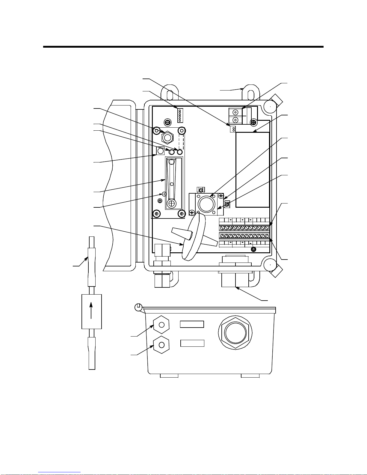
Oxygen
Sensor
Terminal
Strip
Pum p
Mounting
Foot, 4X
_
O
X
Y
G
E
N
B
+
W
OXY
+
RS
IR CO2
Flow Block
IR CO 2
Sensor P CB
BG
Detector/Amp
Terminal Strip
(Factory W ired)
+
+
AMP
AMP 2
S
Sensor Flow
Control Valve
Fail LED
Pilot LED
Pump Reset
Switch
Flowmeter
PressureSwitch
Adjustment Screw
(behind PCB)
R BG
Interconnect
Terminal
Stri p
OXY
GW
+
+
AMP 1
S
+
S
AMP 2
This En d T o
Inlet Fitting
Flowmeter Circuit
Board Connector
Pum p Connector
LEL/ IR
W
Particle Filter
LEL/ IR
W
3/4" Conduit Hub
IR CO2
Sensor
(inside b lock)
Exhaust
Fitting
Inlet
Fitting
EXHAUST
INLET
Hydrophobic
Filter
This section describes the components of the carbon dioxide sample-draw detector.
Figure 1: Carbon Dioxide Sample-Draw Detector Component Location
2 • 35-3001-05-03 Carbon Dioxide Sample-Draw Detector
External Components
Pump
IR CO2
Sensor
Flowmeter
Particle Filter
Flowmeter PCB
Exhaust
Pres su re Switch
Hydrophobic Filter
Inlet
Restrictor
Sensor
Flow
Control
Valve
This section describes the sample-draw detector’s external components.
Housing
The sample-draw detector’s fiberglass housing is weather- and corrosion-resistant. It is suitable for
installation where general purpose equipment is in use.
The housing door is hinged on the left side and is secured by two latches on the right side. The
flowmeter and status LEDs are visible through a window in the housing door.
Four mounting feet are attached to the back of the housing (one at each corner). Use the mounting
feet to install the housing to a vertical surface.
Sample Fittings
The sample fittings are located on the left side of the bottom of the housing. The inlet fitting is near
the front of the housing and the exhaust fitting is near the back of the housing. The sample fittings
accept 1/4 in. rigid tubing. See the Installation section on page 6 to connect tubing to the sample
fittings.
Particle Filter
A particle filter with a tubing stub on one end is shipped with the instrument but it is not factory
installed. If the particle filter is installed directly to the inlet fitting, the tubing stub must be used. If
the particle filter is installed somewhere else, like at the end of the inlet line, the tubing stub can be
used or removed.
Conduit Hub
One 3/4” conduit hub is located on the right side of the bottom of the housing. It is used for routing
wiring into the housing by using conduit or an appropriate cable bushing.
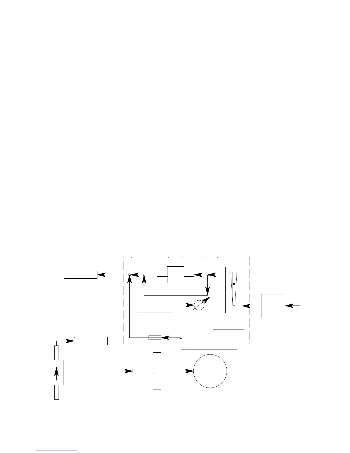
Internal Components
This section describes the sample-draw detector’s internal components (see Figure 1). Figure 2
illustrates how the gas sample moves through the flow system.
Figure 2: Carbon Dioxide Sample-Draw Detector Flow Diagram
35-3001-05-03 Car bon Dioxide Sample-Draw Detecto r • 3
 Loading...