

Page 1

www.rkiinstruments.com
35-3000RK-OXY
Oxygen Sample-Draw Detector
Operator’s Manual
Part Number: 71-0071RK
Revision: P1
Released: 7/18/02
RKI Instruments Inc.
1855 Whipple Road
Hayward, CA 94544
PH: 800-754-5165 Fax: 510-441-5650
Page 2

Product W arranty
RKI Instruments, Inc., warrants gas alarm equipment sold by us to be free from defects in
materials, workmanship, and performance for a period of one year from date of shipment
from RKI Instruments, Inc. Any parts found defective within that period will be repaired
or replaced, at our option, free of charge. This warranty does not apply to those items
which by their nature are subject to deterioration or consumption in normal service, and
which must be cleaned, repaired, or replaced on a routine basis. Examples of such items
are:
a) Absorbent cartridges d) Batteries
b) Pump diaphragms and valves e) Filter elements
c) Fuses
W arranty is voided by abuse including mechanical damage, alteration, r ough handling, or
repair procedures not in accordance with the operator’s manual. This warranty indicates
the full extent of our liability, and we are not responsible for removal or replacement costs,
local repair costs, transportation costs, or contingent expenses incurred without our prior
approval.
THIS WARRANTY IS EXPRESSLY IN LIEU OF ANY AND ALL OTHER
WARRANTIES AND REPRESENTATIONS, EXPRESSED OR IMPLIED,
AND ALL OTHER OBLIGATIONS OR LIABILITIES ON THE PART OF
RKI INSTRUMENTS, INC., INCLUDING BUT NOT LIMITED TO, THE
WARRANTY OF MERCHANTABILITY OR FITNESS FOR A
PARTICULAR PURPOSE. IN NO EVENT SHALL RKI INSTRUMENTS,
INC., BE LIABLE FOR INDIRECT, INCIDENTAL, OR CONSEQUENTIAL
LOSS OR DAMAGE OF ANY KIND CONNECTED WITH THE USE OF
ITS PRODUCTS OR FAILURE OF ITS PRODUCTS TO FUNCTION OR
OPERATE PROPERLY.
This warranty covers instruments and parts sold to users by authorized distributors,
dealers, and representatives as appointed by RKI Instruments, Inc.
We do not assume indemnification for any accident or damage caused by the operation of
this gas monitor, and our warranty is limited to the replacement of parts or our complete
goods.
2 • 35-3000RK-OXY Sample-Draw Oxygen Detector
Page 3

Table of Contents
Overview . . . . . . . . . . . . . . . . . . . . . . . . . . . . . . . . . . . . . . . . . . . . . . . . . . . . . . . . . . . . . . . . . . . 4
Specifications. . . . . . . . . . . . . . . . . . . . . . . . . . . . . . . . . . . . . . . . . . . . . . . . . . . . . . . . . . . . . . . . 4
Description. . . . . . . . . . . . . . . . . . . . . . . . . . . . . . . . . . . . . . . . . . . . . . . . . . . . . . . . . . . . . . . . . . 5
Housing . . . . . . . . . . . . . . . . . . . . . . . . . . . . . . . . . . . . . . . . . . . . . . . . . . . . . . . . . . . . . . . . . . . . . . . . . . . . . 5
Flow System. . . . . . . . . . . . . . . . . . . . . . . . . . . . . . . . . . . . . . . . . . . . . . . . . . . . . . . . . . . . . . . . . . . . . . . . . . 6
Detection System. . . . . . . . . . . . . . . . . . . . . . . . . . . . . . . . . . . . . . . . . . . . . . . . . . . . . . . . . . . . . . . . . . . . . . 7
Installation . . . . . . . . . . . . . . . . . . . . . . . . . . . . . . . . . . . . . . . . . . . . . . . . . . . . . . . . . . . . . . . . . . 9
Mounting the Oxygen Sample-Draw Detector. . . . . . . . . . . . . . . . . . . . . . . . . . . . . . . . . . . . . . . . . . . . . 9
Connecting the Sample Lines to the Sample-Draw Detector. . . . . . . . . . . . . . . . . . . . . . . . . . . . . . . . 10
Wiring the Oxygen Sample-Draw Detector to a Controller . . . . . . . . . . . . . . . . . . . . . . . . . . . . . . . . . 10
Start Up . . . . . . . . . . . . . . . . . . . . . . . . . . . . . . . . . . . . . . . . . . . . . . . . . . . . . . . . . . . . . . . . . . . . 12
Introducing Incoming Power . . . . . . . . . . . . . . . . . . . . . . . . . . . . . . . . . . . . . . . . . . . . . . . . . . . . . . . . . . 12
Setting the Fresh Air Reading. . . . . . . . . . . . . . . . . . . . . . . . . . . . . . . . . . . . . . . . . . . . . . . . . . . . . . . . . . 12
Maintenance. . . . . . . . . . . . . . . . . . . . . . . . . . . . . . . . . . . . . . . . . . . . . . . . . . . . . . . . . . . . . . . . 13
Preventive Maintenance . . . . . . . . . . . . . . . . . . . . . . . . . . . . . . . . . . . . . . . . . . . . . . . . . . . . . . . . . . . . . . 13
Troubleshooting . . . . . . . . . . . . . . . . . . . . . . . . . . . . . . . . . . . . . . . . . . . . . . . . . . . . . . . . . . . . . . . . . . . . . 14
Replacing Components of the Oxygen Sample-Draw Detector . . . . . . . . . . . . . . . . . . . . . . . . . . . . . 15
Adjusting the Low Flow Setting. . . . . . . . . . . . . . . . . . . . . . . . . . . . . . . . . . . . . . . . . . . . . . . . . . . . . . . . 16
Calibration . . . . . . . . . . . . . . . . . . . . . . . . . . . . . . . . . . . . . . . . . . . . . . . . . . . . . . . . . . . . . . . . . 17
Assembling the Calibration Kit . . . . . . . . . . . . . . . . . . . . . . . . . . . . . . . . . . . . . . . . . . . . . . . . . . . . . . . . 17
Setting the Fresh Air Reading. . . . . . . . . . . . . . . . . . . . . . . . . . . . . . . . . . . . . . . . . . . . . . . . . . . . . . . . . . 17
Setting the Zero Reading . . . . . . . . . . . . . . . . . . . . . . . . . . . . . . . . . . . . . . . . . . . . . . . . . . . . . . . . . . . . . . 18
Parts List . . . . . . . . . . . . . . . . . . . . . . . . . . . . . . . . . . . . . . . . . . . . . . . . . . . . . . . . . . . . . . . . . . . 19
35-3000RK-OXY Sample-Draw Oxygen Detector • 3
Page 4
Overview
This instruction manual describes the 35-3000RK-OXY sample-draw oxygen detector . This
manual also describes how to install, start up, maintain, and calibrate the sample-draw
detector when using it with a gas monitoring controller. A parts list at the end of this
manual lists replacement parts and accessories for the sample-draw oxygen detector. See
the operator’s manual for the controller for information specific to the controller
Specifications
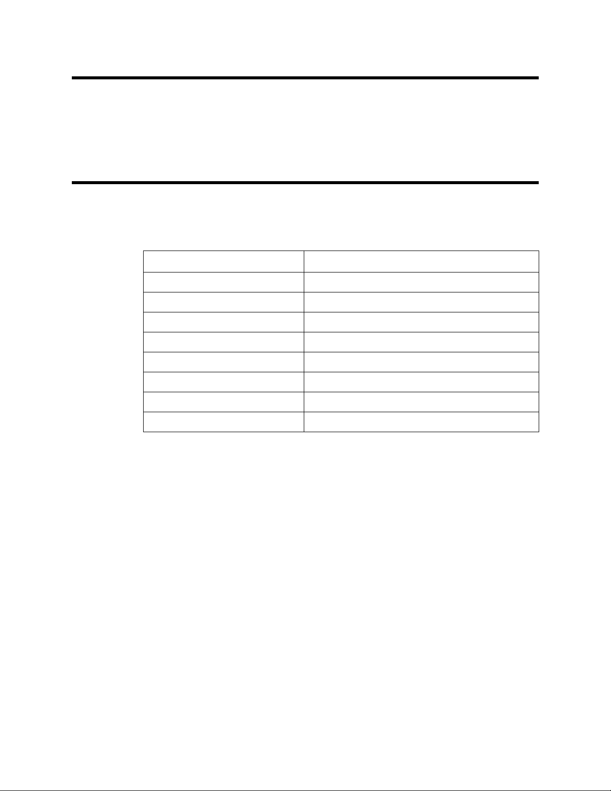
Table 1 lists specifications for the sample-draw oxygen detector.
Table 1: Specifications
Target Gas Oxygen (O
Input Power 24 VDC Nominal (23 VDC - 28 VDC)
Construction (housing) Fiberglass/polyester (NEMA 4X)
Dimensions 8.5 in. H x 6.5 in. W x 4.25 in. D
Weight 4.5 lbs.
Sampling Method Sample-draw
Sample Flow 1.5 SCFH (nominal)
Detection Range 0 to 25.0% (by volume)
Response Time 90% in 30 seconds
)
2
4 • 35-3000RK-OXY Sample-Draw Oxygen Detector
Page 5
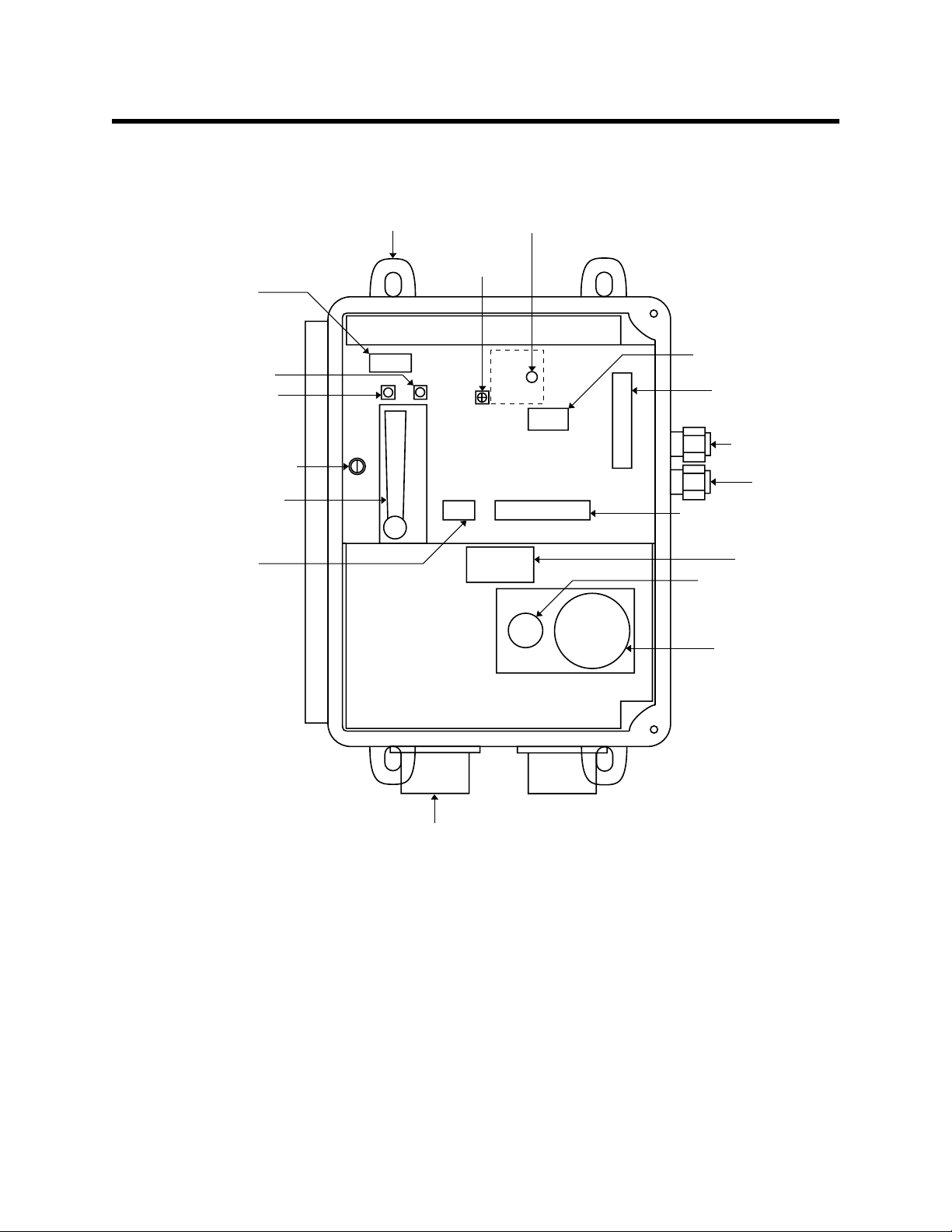
Description
Pilot light
This section describes the components of the sample-draw oxygen detector. The sampledraw detector consists of the housing, flow system, and detection system.
Mounting foot
(total of 4)
Flow adjust
potentiometer
Pump
terminal strip
Fail light
Bypass valve
Flowmeter
Low flow
potentiometer
Relay
Detector
terminal strip
EXHAUST fitting
INLET fitting
Interconnect terminal strip
Power
terminal strip
(not used)
Conduit hub
(total of 2)
Filter
Combustible gas sensor
(not used in this version)
Oxygen sensor
Figure 1: Sample-draw Oxygen Detector Component Location
Housing
The sample-draw detector’s fiberglass housing is weather- and corrosion-resistant. It is
suitable for installation where general purpose equipment is in use.
The housing door is hinged on the left side and is secured by two latches on the right side.
The flowmeter and status lights are visible through a window in the housing door.
Four mounting feet are attached to the back of the housing (one at each corner). Use the
mounting feet to install the housing to a vertical surface. Use the two conduit hubs on the
bottom of the housing to make wiring connections.
An aluminum subpanel is mounted to the interior of the housing. The sample-draw
detector’s internal components are mounted to the subpanel.
35-3000RK-OXY Sample-Draw Oxygen Detector • 5
Page 6
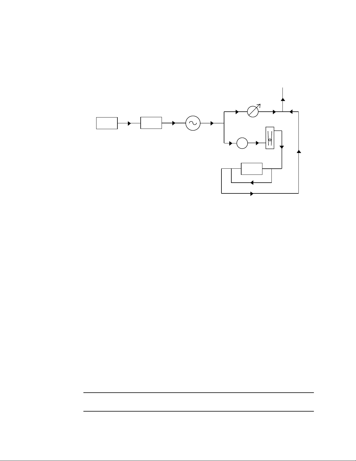
Flow System
The sample-draw detector’s flow system consists of the inlet fitting, filter, pump,
flowmeter, bypass valve, status lights, pressure switch, and exhaust fitting (see
Figure 1). Figure 2 illustrates how the gas sample moves through the flow system.
Bypass
Valve
Flowmeter
Inlet Filter Pump Sensor
Pressure Switch
To
Exhaust
Figure 2: Sample-draw Oxygen Detector Flow Diagram
Inlet fitting
The inlet fitting on the right side of the housing allows the gas sample to enter the sampledraw detector. The inlet fitting accepts 1/4 in. rigid tubing. See the Installation section on
page 9 to connect tubing to the inlet fitting.
Filter
The dust filter is below the main circuit board. The filter prevents particulates in the
incoming gas sample from damaging the flow and detection systems. Replace the filter
when it appears dirty, discolored, or clogged.
Pump
The pump is behind the main circuit board near the top of the sample-draw detector.
The pump pulls the gas sample into the sample-draw detector. The pump operates on
24 VAC, which is generated from the 24 VDC supplied to the sample draw detector.
Flowmeter
The flowmeter is attached to the main circuit board near the top left corner (see Figure 1.)
You can see it through the window in the door. A ball in the flowmeter column indicates
the flow rate of the sample-draw detector. The flowmeter measures the flow in the range
0.2 to 2.0 SCFH (Standard Cubic Feet per Hour). The optimum flow rate is 1.5 SCFH.
Bypass valve
The bypass valve is to the left of the flowmeter. The bypass valve adjusts the flow rate to
the sensor. Use a flat-blade screwdriver to adjust the bypass valve.
NOTE: The bypass valve allows fine adjustments of the flow rate. For a wider range of
adjustment, use the flow adjust potentiometer (see Figure 1.)
6 • 35-3000RK-OXY Sample-Draw Oxygen Detector
Page 7

Status lights
Two status lights are above the flowmeter. They are also visible through the window in
the housing door.
Pilot light
The green Pilot light is on when the sample-draw detector is receiving power from the
Controller.
Fail light
The red fail light is on when the sample flow rate is below the low flow level
NOTE: The factory set low flow level is 0.6 SCFH (±0.2). See “Adjusting the Low Flow
Setting” on page 16 to adjust this setting.
Pressure switch
The pressure switch is mounted to the opposite side of the main circuit board. The
pressure switch monitors the flow rate of the incoming gas sample.
If the flow rate falls below the preset low flow level, the pressure switch causes the fail
relay to interrupt the signal from the sensor. The interrupted sensor signal causes a fail
condition at the controller. The low flow level is factory-set at 0.6 SCFH (±0.2 SCFH).
Exhaust fitting
The exhaust fitting on the right side of the housing allows the gas sample to exit the
sample-draw detector . The exhaust fitting accepts 1/4 in. rigid tubing. See the Installation
section on page 9 to connect tubing to the exhaust fitting.
Detection System
The detection system consists of the oxygen sensor and the main circuit board.
Oxygen sensor
The oxygen sensor is installed in a cavity block. The cavity block is mounted to the
aluminum subpanel near the bottom of the sample-draw detector. The oxygen sensor
includes the oxygen cell, connector, and sensor leads.
NOTE: The cavity block includes a cavity for a combustible gas sensor. This version of
the sample-draw detector does not include the combustible gas sensor.
Oxygen cell
The oxygen cell is protected within the sensor assembly. Through a series of chemical and
electronic reactions, the cell produces a millivolt output that is proportional to the
detection range of the sample-draw detector.
Connector
The cable that extends from the sensor terminates in a 7-position socket that connects to a
mating 7-pin male connector. The socket and connector allow you to replace the sensor
without disconnecting the wiring. The sensor leads are soldered to the male connector.
Sensor leads
Two color-coded leads extend from the connector. The leads allow you to connect the
oxygen sensor to the main circuit board.
35-3000RK-OXY Sample-Draw Oxygen Detector • 7
Page 8

Main Circuit Board
The main circuit board includes the interconnect terminal strip, detector terminal strip,
pump terminal strip, and relay (see Figure 1).
NOTE: The flowmeter and status lights are mounted to the main circuit board but are
considered part of the flow system.
Interconnect terminal strip
The interconnect terminal strip is the nine-point terminal strip near the bottom edge of the
main circuit board. Use the interconnect terminal strip to connect the sample-draw
detector to a controller.
Detector terminal strip
The detector terminal strip is the nine-point terminal strip near the right edge of the circuit
board. Use the detector terminal strip to connect the oxygen sensor to the main circuit
board.
NOTE: The oxygen sensor is factory-wired to the circuit board. See the “Installation”
section on page 9 for all wiring procedures related to the sample-draw detector.
Pump terminal strip
The pump terminal strip is the four-point terminal strip near the top edge of the circuit
board. Use the pump terminal strip to connect the pump and pressure switch to the main
circuit board.
NOTE: The pump and pressure switch are factory-wired to the circuit board.
Relay
The relay is to the left of the detector terminal strip. The relay is single-pole, double-throw
(SPDT) and is rated for 2 amps at 25 VDC (resistive). If the pressure switch senses a low
flow condition, the relay interrupts the signal from the sensor. The interrupted sensor
signal causes a fail condition at the controller.
NOTE: No relay contacts are available for use in controlling an external device.
8 • 35-3000RK-OXY Sample-Draw Oxygen Detector
Page 9

Installation
This section describes procedures to mount the sample-draw oxygen detector in the
monitoring environment and wire the sample-draw detector to a controller.
Mounting the Sample-Draw Detector
1. Select the mounting site. Consider the following when you select the mounting site.
• Is there enough room to open the housing door and make wiring connections at
the bottom of the housing and tubing connections at the right of the housing?
Make sure there is sufficient room to perform start-up, maintenance, and
calibration procedures.
• Are the flowmeter and status lights visible?
7.3 in.
6.5 in.
4.0 in.
8.5
in.
8.9
in.
9.3
in.
Note: The housing is 4.25 in. deep.
Figure 3: Mounting the Sample-Draw Oxygen Detector
3/4 in. conduit hub
(total of 2 hubs)
35-3000RK-OXY Sample-Draw Oxygen Detector • 9
Page 10

2. Close and latch the housing door.
NOTE: The sample-draw detector is shipped with the mounting feet “tucked under” the
housing to protect the mounting feet during shipment.
3. Slightly loosen the screw that secures the mounting foot to the housing, then rotate
the mounting foot 180 degrees (see Figure 3).
4. Tighten the screw that secures the mounting foot to the housing.
5. Repeat steps 3 and 4 for the remaining three mounting feet.
6. Position the sample-draw housing on a vertical surface at eye level (4 1/2 to 5 feet
from the floor).
7. Insert 1/4 in. or 5/16 screws through the slots in the mounting feet to secure the
housing to the mounting surface.
Connecting the Sample Lines to the Sample-Draw Detector
1. Attach 1/4 in. metal or plastic rigid sample tubing to the inlet fitting.
CAUTION: If you use flexible sample tubing (vinyl or polyurethane for example), use an
appropriate metal insert to seal the connection between the tubing and the inlet
fitting. See the Parts List at the end of this manual for an example of an appropriate
metal insert.
2. Place the opposite end of the tubing at the sampling area.
CAUTION: Avoid loops or slumps in the incoming sample line. To reduce response time, keep the
incoming sample line as short as possible.
3. Attach rigid sample tubing to the exhaust fitting.
4. Route the opposite end of the tubing to an open area where the sample can safely
disperse.
Wiring the Sample-Draw Detector to a Controller
WARNING: Always verify that the controller is off and that power to the controller is
off before you make wiring connections.
1. Turn off the controller
2. Turn off power to the controller.
3. Unlatch and open the housing door of the sample-draw detector.
4. Guide a four-conductor, shielded cable or four wires in conduit through one of the
conduit hubs at the bottom of the sample-draw housing.
5. Connect the cable to the sample-draw detector’s interconnect terminal strip as shown
in Figure 4.
6. Close and latch the housing door of the sample-draw detector.
10 • 35-3000RK-OXY Sample-Draw Oxygen Detector
Page 11

CAUTION: If using shielded cable, leave the cable’s drain wir e insulated and disconnected at the
sample-draw detector. You will connect the opposite end of the drain wire at the
controller.
7. Route the cable or wires in conduit leading from the sample-draw detector through
one of the conduit hubs on the controller.
CAUTION: At the controller, do not route controller power and sample-draw detector wiring
through the same conduit hub. The controller power cable may disrupt the
transmission of the sample-draw detector signal to the controller.
8. Connect the wires to the applicable detector terminal strip and power terminals at the
controller as shown in Figure 4.
OxygenSample Draw Housing
Pump,
Internally
Wired
Pressure Switch,
Internally Wired
PSW
PUMP
Controller Oxygen
Detector Terminals
ControllerTerminals
Or PowerSupply
PCB in Single Point
Sample- Drawing
Detector
GNDH
N
115VAC
NotUsedOn
ThisVersion
RD
White (+)
Green (-)
-(DC Ground)
+( 23 VDC - 28 VDC)
WHT GRN BLK GND
LEL/ O2 AMP
24V
4/20
+
P- AMP
ToOxygen
Sensor
Green
White
_
Figure 4: Wiring the Sample-Draw Oxygen Detector to a Controller
5. Connect the cable shield to an available chassis ground. The grounding screw on one
of the controller’s grounded conduit hubs is an example of a chassis ground.
35-3000RK-OXY Sample-Draw Oxygen Detector • 11
Page 12

Start Up
This section describes procedures to start up the sample-draw oxygen detector and place
the sample-draw detector into normal operation.
Introducing Incoming Power
1. Complete the installation procedures described earlier in this manual.
2. Verify that the power wiring is correct and secure. Refer to the controller instruction
manual for connections at the controller.
3. Turn on or plug in the incoming power at the power source end, then turn on the
controller.
4. Verify that the sample-draw detector’s PILOT light is on.
5. Verify that the controller is on and operating properly. Refer to the controller
instruction manual.
6. Verify that the flowmeter indicates a flow rate of approximately 1.5 SCFH. If
necessary, use the bypass valve or flow adjust potentiometer to adjust the flow rate.
NOTE: The following step tests for leaks in the sample line. This test will cause a low
flow condition at the sample-draw detector and a fail condition at the controller.
Be sure to put the controller into its calibration program or disable external
alarms before performing this test.
7. Verify that the incoming sample line is not leaking. To test the sample line, plug the
open end of the sample line with your thumb. If the flowmeter ball drops to the
bottom of the flowmeter, the incoming sample line is not leaking.
8. Remove your thumb from the sample line, verify that the flowmeter returns to a
normal flow rate.
9. If alarms were disabled at the controller, enable them.
Setting the Fresh Air Reading
CAUTION: If you suspect the monitoring environment is not of normal oxygen content (20.9%),
use the calibration kit and zero air calibration cylinder to introduce “fresh air” to the
detector and verify an accurate normal setting.
1. Verify that the sample-draw detector is sampling a fresh air environment
(environment known to be of normal oxygen content).
2. Verify a reading of 20.9% at the controller.
If the display reading is 20.9%, start up is complete. The sample-draw oxygen detector
is in normal operation. If the display reading is not 20.9%, continue with step 3.
3. Perform a zeroing operation at the controller. See the controller instruction manual for
directions.
12 • 35-3000RK-OXY Sample-Draw Oxygen Detector
Page 13

Maintenance
This section describes maintenance procedures. It includes preventive maintenance
procedures. This section also includes procedures to troubleshoot the sample-draw
detector, replace components of the sample-draw detector, and adjust the low flow
setting.
Preventive Maintenance
This section describes a preventive maintenance schedule to ensure the optimum
performance of the sample-draw detector. It includes daily, monthly, and quarterly
procedures.
Daily
1. Verify that the pilot light is on.
2. Verify that the flowmeter indicates a flow rate of approximately 1.5 SCFH.
3. Verify a reading of 20.9% at the controller. Investigate significant changes in the
Monthly
If necessary use the bypass valve or flow adjust potentiometer to adjust the flow rate
to 1.5 SCFH.
reading.
This procedure describes a test to verify that the sample-draw detector responds pr operly
to oxygen deficiency.
NOTE: To reduce the response time of this test, use a short incoming sample line. If the
sample-draw detector’s sample line is long, connect a shorter line for this test.
Make sure you reconnect the sample line after you complete this procedure.
NOTE: Performing a response test on the sample-draw detector may cause alarms. Be
sure to put the controller into its calibration program or disable external alarms
before performing this test
Performing the response test
1. Exhale into the sample-draw detector’s incoming sample line.
2. Stop exhaling into the sample line, then verify that the readings at the controller
decreased.
NOTE: If the reading does not decrease, calibrate the sample draw detector as described
in the “Calibration” section on page 17.
Quarterly
Calibrate the sample-draw detector as described in the “Calibration” section on page 17.
35-3000RK-OXY Sample-Draw Oxygen Detector • 13
Page 14

Troubleshooting
The troubleshooting guide describes symptoms, probable causes, and recommended
action for problems you may encounter with the sample-draw detector.
NOTE: This troubleshooting guide describes sample-draw detector problems only. See
the controller instruction manual for problems you may encounter with the
controller.
Fail condition
Symptoms
• The sample-draw detector’s FAIL light is on.
• The controller is operating properly but indicates a reading well below zero.
Probable causes
• The detector wiring is disconnected or misconnected.
• The sample-draw detector’s flow rate is too low because of an obstructed sample line,
failed pump, etc.
• The sample-draw detector is malfunctioning.
Recommended action
1. At the sample-draw detector, set the correct flow rate with the bypass valve or flow
adjust potentiometer.
2. If you cannot set the correct flow rate, check the sample lines for obstructions or kinks.
3. Verify that the detector wiring is correct and secure. The Installation section on page 9
describes detector wiring connections.
4. Calibrate the sample-draw detector as described in the Calibration section on page 17.
5. If the fail condition continues, replace the oxygen sensor as described later in this
section.
6. If the fail condition continues, contact RKI Instruments, Inc., for further instruction.
Slow or no response/difficult or unable to calibrate
Symptoms
• The detector responds slowly or does not respond during the monthly response test.
• Unable to accurately set the fresh air or zero reading during the calibration pr ocedur e.
• The detector requires frequent calibration.
NOTE: Under “normal” circumstances, the detector r equires calibration once every thr ee
months. Some applications may require a more frequent calibration schedule.
Probable causes
• The calibration cylinder is low, out-dated, or defective.
• The sample-draw detector’s flow rate is too low because of an obstructed sample line,
failed pump, etc.
• The sample-draw detector is malfunctioning.
14 • 35-3000RK-OXY Sample-Draw Oxygen Detector
Page 15

Recommended action
1. Verify that the calibration cylinder contains an adequate supply of a fresh test sample.
2. If necessary, set the correct flow rate with the bypass valve or flow adjust
potentiometer.
3. If you cannot set the correct flow rate, check the sample line for obstructions or kinks.
4. If the calibration/response difficulties continue, replace the oxygen sensor as
described later in this section.
5. If the calibration/response difficulties continue, contact RKI Instruments, Inc., for
further instruction.
Replacing Components of the Oxygen Sample-draw Detector
This section includes procedures to replace the sensor, filter, and ferrules.
Replacing the oxygen sensor
1. Turn off the controller.
2. Turn off power to the controller.
3. Open the housing door of the sample-draw detector.
4. Unscrew and remove the two screws that secure the sensor retraining plate, then lift
the plate, connector, and sensor out of the housing.
5. Unplug the connector from the senor cable socket.
6. Plug the socket of the replacement sensor into the connector.
7. Place the sensor in the oxygen sensor cavity, then position the retaining plate on the
two standoffs.
8. Secure the retaining plate to the standoffs with the two screws you removed in step 4.
9. Turn on power to the controller.
10. Turn on the controller.
11. Calibrate the replacement sensor as described in the “Calibration” section on page 17.
Replacing the filter
1. Turn off the controller.
2. Turn off power to the controller.
3. Open the housing door of the sample-draw detector.
4. Note the direction of the arrow on the filter. The arrow indicates the direction of the
sample flow.
5. Disconnect the filter from the elbows on each end of the filter, then remove the filter
from the sample-draw detector.
6. Make sure the arrow is pointing in the same direction as the arrow on the filter you
removed, then connect each end of the replacement filter to the elbows.
7. Verify that the flow rate is approximately 1.5 SCFH, then close the housing door.
8. Turn on power to the controller.
9. Turn on the controller.
35-3000RK-OXY Sample-Draw Oxygen Detector • 15
Page 16

Replacing the ferrules
Both the inlet and exhaust fittings include two ferrules that seal the inlet or exhaust tubing
to the fitting. Replace the ferrules if the seal is bad or if you replace the sample tubing.
Always replace the ferrules as a pair.
1. Disconnect the sample tubing from the fitting, then unscrew the nut from the fitting.
2. Verify that the ferrules did not remain in the nut. If necessary, remove the ferrules
from the nut.
3. Position the nut so the threaded end is facing you, then insert the bottom (smaller)
ferrule into the nut. Insert the ferrule so the flat side is facing down.
NOTE: Make sure the bottom ferrule is laying flat in the nut.
4. Insert the cone-shaped front ferrule on top of the bottom ferrule. Insert the ferrule so
the smaller end of the cone is facing up.
5. Screw the nut onto the fitting, then connect the sample tubing to the fitting. Make sure
you firmly tighten the tubing to the fitting.
Adjusting the Low Flow Setting
NOTE: Adjusting the low flow setting will cause a low flow alarm at the sample-draw
detector and a fail alarm at the controller. Be sure to put the controller into its
calibration program or disable external alarms before performing this test
The factory-set low flow setting is 0.6 SCFH (±0.2). To adjust the low flow setting:
1. Use the flow adjust potentiometer (VR1) to set the flow to 0.6 SCFH.
If the sample-draw detector goes into low flow alarm before you can adjust the flow
down to 0.6 SCFH, adjust the low flow potentiometer 1/4 turn clockwise, then
attempt to set the flow again. Repeat this step until you are able to adjust the flow to
0.6 SCFH.
2. Slowly turn the low flow potentiometer counterclockwise just until the sample-draw
detector goes into low flow alarm.
NOTE: The low flow potentiometer is accessible through a circular cutout in the main
circuit board. The cutout is labeled PS1.
3. Increase the flow using VR1 until the unit is out of low flow alarm.
4. Decrease the flow very slowly and verify that the low flow alarm is 0.6 SCFH (±0.2).
If the low flow alarm is set too low, turn the low flow potentiometer slightly
clockwise. Repeat steps 3 and 4 if necessary.
5. Use the flow adjust potentiometer (VR1) to set the flow to 1.5 SCFH.
6. Make sure the sample draw detector’s Fail light is off.
16 • 35-3000RK-OXY Sample-Draw Oxygen Detector
Page 17

Calibration
This section describes how to calibrate the sample-draw oxygen detector. It includes
procedures to assemble the calibration kit, set the fresh air reading, set the zero reading,
and return to normal operation.
NOTE: Calibrating the sample draw detector may cause alarms. Be sure to put the
controller into its calibration program or disable external alarms before
continuing.
NOTE: This procedure describes calibration using a gas collection bag. A demand-flow
calibration kit is also available for calibrating the sample-draw detector.
Assembling the Calibration Kit
NOTE: If you can verify a fresh air environment, it is not necessary to use a zero air
calibrating sample to set the fresh air reading at the controller.
1. Screw the dispensing valve onto the zero air calibration cylinder.
2. Connect the calibration kit sample tubing to the fitting on the gas collection bag.
3. Disconnect the incoming sample line from the sample-draw detector’s inlet fitting,
then connect the sample tubing from the gas collection bag to the inlet fitting.
Allow the sample-draw pump to draw out any residual gas in the gas collection bag.
4. Close the tubing clamp. The tubing clamp is attached to the calibration kit sample
tubing.
5. Disconnect the calibration kit sample tubing from the inlet fitting.
6. Connect the tubing from the gas collection bag to the dispensing valve, then open the
clamp.
7. Open the dispensing valve. The gas collection bag begins to fill.
8. Close the dispensing valve when the gas collection bag appears full.
9. Close the tubing clamp, then disconnect the sample tubing from the dispensing valve.
Setting the Fresh Air Reading
1. Open the clamp, then connect the sample tubing from the gas collection bag to the
sample-draw detector’s inlet fitting.
2. Allow the sample draw detector to draw sample for one minute.
3. Follow the directions in the controller’s instruction manual for setting the fresh air
reading.
4. Allow the sample-draw detector to draw out any residual gas in the gas collection
bag.
5. Disconnect the gas bag sample tubing from the inlet fitting, then close the tubing
clamp.
6. Unscrew the dispensing valve from the zero air calibration cylinder.
35-3000RK-OXY Sample-Draw Oxygen Detector • 17
Page 18

Setting the Zero Reading
1. Screw the dispensing valve onto the 100% N2 calibration cylinder.
2. Connect the sample tubing from the gas collection bag to the dispensing valve, then
open the tubing clamp.
3. Open the dispensing valve. The gas collection bag begins to fill.
4. Close the dispensing valve when the gas collection bag appears full.
5. Close the tubing clamp, then disconnect the sample tubing from the dispensing valve.
Open the tubing clamp, then connect the sample tubing from the gas collection bag to
the sample-draw detector’s inlet fitting.
6. Allow the sample-draw detector to draw the calibrating sample for 1 minute.
7. Follow the directions in the controller’s instruction manual for setting the zero
(oxygen free) reading.
8. Allow the sample-draw detector to draw out any residual gas in the gas collection
bag.
9. Disconnect the sample tubing from the sample-draw detector’s inlet fitting.
10. Reconnect the incoming sample line to the inlet fitting.
11. Unscrew the dispensing valve from the calibration cylinder.
12. Wait 1 to 2 minutes to allow the oxygen reading at the controller to return to normal,
then return the controller to normal operation.
NOTE: If you do not allow the oxygen reading to return to normal, then unwanted
alarms may occur.
13. Verify that the controller display reading stabilizes at 20.9%.
14. Store the components of the calibration kit in a safe and convenient place.
18 • 35-3000RK-OXY Sample-Draw Oxygen Detector
Page 19

Parts List
Table 3 lists replacement parts and accessories for the sample-draw oxygen detector.
Table 2: Parts List
Part Number Description
06-1248RK Sample tubing, 3/16 x 5/16, specify length (for calibration kit)
17-2593RK Brass insert (for inlet and exhaust fittings)
17-2683RK Front ferrule (for inlet and exhaust fittings)
17-2688RK Back ferrule (for inlet and exhaust fittings)
30-0610RK Pump
33-0163RK Filter (Balston DFU9933-05-DQ)
65-0601RK Oxygen sensor (plug-in type)
71-0071RK Operator’s Manual, 35-3000RK-OXY Oxygen Sample-Draw Detector
81-0076RK-01 Zero air calibration cylinder (34 liter)
81-0076RK-03 Zero air calibration cylinder (103 liter)
81-0078RK Calibration cylinder (100% Nitrogen; 17 liter)
81-0078RK-01 Calibration cylinder (100% Nitrogen; 34 liter)
81-0078RK-03 Calibration cylinder (100% Nitrogen; 103 liter)
81-1001RK Dispensing valve with knob, for 17 liter & 34 liter cylinders
81-1054RK Demand flow regulator, for 103 liter cylinder
81-1126RK Gas collection bag (2 liter)
81-F301RKS-LV Calibration kit (includes gas collection bag, 100% Nitrogen and
zero air calibration cylinders)
81-F302RKS-LV Calibration kit (includes gas collection bag and 100% Nitrogen
calibration cylinder)
35-3000RK-OXY Sample-Draw Oxygen Detector • 19
 Loading...