

Page 1

35-3000RK-LEL/O
Sample-Draw Detector
Operator’s Manual
Part Number: 71-0223RK
Revision: P1
Released: 2/28/11
www.rkiinstruments.com
Page 2

WARNING
Read and understand this instruction manual before operating
detector . Improper use of the dete ctor could result in bodily harm
or death.
Periodic calibration and maintenance of the detector is essential
for proper operation and correct readings. Please calibrate and
maintain this detector regularly! Frequency of calibration
depends upon the type of use you have and the sensor types.
T ypical calibration frequencies for most applications a re between
3 and 6 months, but can be required more often or less often
based on your usage.
35-3000RK-LEL/O Sample-Draw Detecto r
Page 3

Product Warranty
RKI Instruments, Inc. warrants gas alarm equipment sold by us to be free fro m defects in
materials, workmanship, and performance for a period of one year fr o m date of shipment
from RKI Instruments, Inc. Any parts found defective withi n tha t period will be repaired
or replaced, at our option, free of charge. This warranty does not apply to those items
which by their nature are subject to deterioration or consumption in normal ser v ice, and
which must be cleaned, repaired, or replaced on a routine basis. Examples of such items
are:
W arranty is voided by abuse including mechanical damage, alteration, rough handling, or
repair procedures not in accordance with the operator’s manual. This warranty indicates
the full extent of our liability , a nd we are not r esponsible for removal or r eplacement costs,
local repair costs, transportation costs, or contingent expenses incurred without our prior
approval.
a) Absorbent cartridges d) Batteries
b) Pump diaphragms and valves e) Filter elements
c) Fuses
THIS WARRANTY IS EXPRESSLY IN LIEU OF ANY AND ALL OTHER
WARRANTIES AND REPRESENTATIONS, EXPRESSED OR IMPLIED,
AND ALL OTHER OBLIGATIONS OR LIABILITIES ON THE PART OF
RKI INSTRUMENTS, INC. INCLUDING BUT NOT LIMITED TO, THE
WARRANTY OF MERCHANTABILITY OR FITNESS FOR A
PARTICULAR PURPOSE. IN NO EVENT SHALL RKI INSTRUMENTS,
INC. BE LIABLE FOR INDIRECT, INCIDENTAL, OR CONSEQUENTIAL
LOSS OR DAMAGE OF ANY KIND CONNECTED WITH THE USE OF
ITS PRODUCTS OR FAILURE OF ITS PRODUCTS TO FUNCTION OR
OPERATE PROPERLY.
This warranty covers instruments and parts sold to users by authorized distributors,
dealers, and representatives as appointed by RKI Instruments, Inc.
We do not assume indemnification fo r any accident or dama g e ca u s e d by the operation of
this gas monitor, and our warranty is limited to the replacement of parts or our complete
goods.
35-3000RK-LEL/O Sample-Dr aw Detector
Page 4

Table of Contents
Overview . . . . . . . . . . . . . . . . . . . . . . . . . . . . . . . . . . . . . . . . . . . . . . . . . . . . . . . . . . . . . . . . . . . 1
Specifications. . . . . . . . . . . . . . . . . . . . . . . . . . . . . . . . . . . . . . . . . . . . . . . . . . . . . . . . . . . . . . . . 1
Description. . . . . . . . . . . . . . . . . . . . . . . . . . . . . . . . . . . . . . . . . . . . . . . . . . . . . . . . . . . . . . . . . . 2
Housing . . . . . . . . . . . . . . . . . . . . . . . . . . . . . . . . . . . . . . . . . . . . . . . . . . . . . . . . . . . . . . . . . . . . . . . . . . . . . 2
Flow System. . . . . . . . . . . . . . . . . . . . . . . . . . . . . . . . . . . . . . . . . . . . . . . . . . . . . . . . . . . . . . . . . . . . . . . . . . 3
Detection System. . . . . . . . . . . . . . . . . . . . . . . . . . . . . . . . . . . . . . . . . . . . . . . . . . . . . . . . . . . . . . . . . . . . . . 4
Installation . . . . . . . . . . . . . . . . . . . . . . . . . . . . . . . . . . . . . . . . . . . . . . . . . . . . . . . . . . . . . . . . . . 7
Mounting the Sample-Draw Detector . . . . . . . . . . . . . . . . . . . . . . . . . . . . . . . . . . . . . . . . . . . . . . . . . . . . 7
Connecting the Sample Lines to the Sample-Draw Detector. . . . . . . . . . . . . . . . . . . . . . . . . . . . . . . . . 8
Wiring the Sam ple-Draw Detector to a Controller . . . . . . . . . . . . . . . . . . . . . . . . . . . . . . . . . . . . . . . . . 8
Start Up. . . . . . . . . . . . . . . . . . . . . . . . . . . . . . . . . . . . . . . . . . . . . . . . . . . . . . . . . . . . . . . . . . . . 10
Introducing Incoming Power . . . . . . . . . . . . . . . . . . . . . . . . . . . . . . . . . . . . . . . . . . . . . . . . . . . . . . . . . . 10
Setting the Zero/Fresh Air Reading . . . . . . . . . . . . . . . . . . . . . . . . . . . . . . . . . . . . . . . . . . . . . . . . . . . . 10
Maintenance. . . . . . . . . . . . . . . . . . . . . . . . . . . . . . . . . . . . . . . . . . . . . . . . . . . . . . . . . . . . . . . . 11
Preventive Maintenance . . . . . . . . . . . . . . . . . . . . . . . . . . . . . . . . . . . . . . . . . . . . . . . . . . . . . . . . . . . . . . 11
Troubleshooting . . . . . . . . . . . . . . . . . . . . . . . . . . . . . . . . . . . . . . . . . . . . . . . . . . . . . . . . . . . . . . . . . . . . . 12
Replacing Components of the Sample-Draw Detector. . . . . . . . . . . . . . . . . . . . . . . . . . . . . . . . . . . . . 13
Adjusting the Low Flow Setting. . . . . . . . . . . . . . . . . . . . . . . . . . . . . . . . . . . . . . . . . . . . . . . . . . . . . . . . 15
Calibration Frequency . . . . . . . . . . . . . . . . . . . . . . . . . . . . . . . . . . . . . . . . . . . . . . . . . . . . . . . 15
Calibration, Combustible Sensor . . . . . . . . . . . . . . . . . . . . . . . . . . . . . . . . . . . . . . . . . . . . . 16
Preparing for Calibration. . . . . . . . . . . . . . . . . . . . . . . . . . . . . . . . . . . . . . . . . . . . . . . . . . . . . . . . . . . . . . 16
Setting the Zero Reading. . . . . . . . . . . . . . . . . . . . . . . . . . . . . . . . . . . . . . . . . . . . . . . . . . . . . . . . . . . . . . 16
Setting the Response Reading. . . . . . . . . . . . . . . . . . . . . . . . . . . . . . . . . . . . . . . . . . . . . . . . . . . . . . . . . . 16
Returning to Normal Operation. . . . . . . . . . . . . . . . . . . . . . . . . . . . . . . . . . . . . . . . . . . . . . . . . . . . . . . . 17
Calibration, Oxygen Sensor . . . . . . . . . . . . . . . . . . . . . . . . . . . . . . . . . . . . . . . . . . . . . . . . . . 17
Preparing for Calibration. . . . . . . . . . . . . . . . . . . . . . . . . . . . . . . . . . . . . . . . . . . . . . . . . . . . . . . . . . . . . . 17
Setting the Fresh Air Reading. . . . . . . . . . . . . . . . . . . . . . . . . . . . . . . . . . . . . . . . . . . . . . . . . . . . . . . . . . 17
Setting the Zero Reading. . . . . . . . . . . . . . . . . . . . . . . . . . . . . . . . . . . . . . . . . . . . . . . . . . . . . . . . . . . . . . 17
Returning to Normal Operation. . . . . . . . . . . . . . . . . . . . . . . . . . . . . . . . . . . . . . . . . . . . . . . . . . . . . . . . 18
Parts List . . . . . . . . . . . . . . . . . . . . . . . . . . . . . . . . . . . . . . . . . . . . . . . . . . . . . . . . . . . . . . . . . . . 19
35-3000RK-LEL/O Sample-Draw Detecto r
Page 5
Overview
This operator’s manual describes the 35-3000RK-LEL/O sample-draw detector. This
manual also describes how to install, start up, maintain, and calibrate the sample -draw
detector when using it with a gas monitoring controller. A parts list at th e end of this
manual lists replacement parts and accessories for the sample-draw detector.
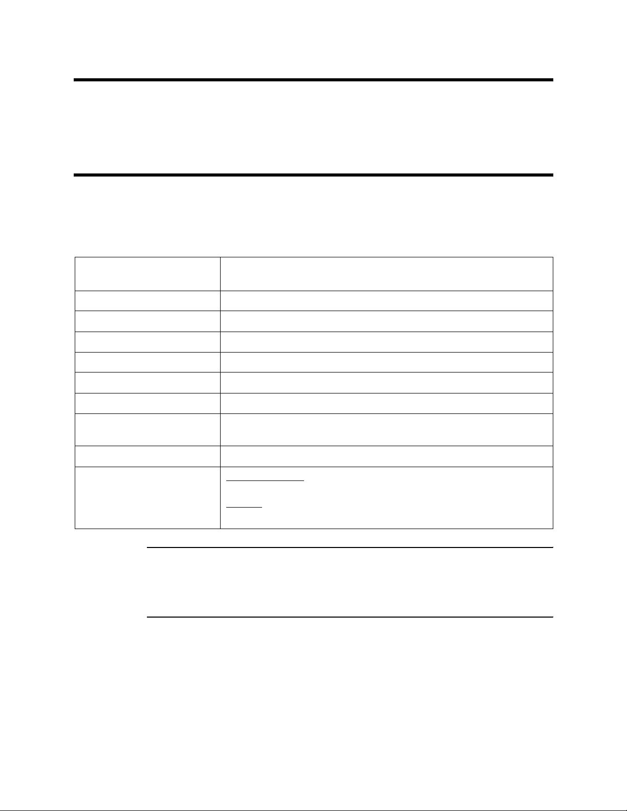
Specifications
Table 1 lists specifications for the sample-draw detector. See the controller operator’s
manual for information specif ic to the controller.
Table 1: Specifications
Target Gas Combustible gas, methane calibra tion standard
Oxygen
Input Power 24 VDC Nominal (23 VDC - 28 VDC)
Construction (housing) Fiberglass/polyester (NEMA 4X)
Dimensions 8.5 in. H x 6.5 in. W x 4.25 in. D
Weight 4.5 lbs.
Sampling Method Sample-draw
Sample Flow 1.5 SCFH (nominal)
Detection Range Combustible gas: 0 to 100% L E L
Oxygen: 0 to 25% volume
Response Time 90% in 30 seconds
Accuracy Combustible Gas
± 5% of reading or ± 2% LEL (whichever is greater)
Oxygen
± 0.5% O
WARNING: When using the 35-3000RK-LEL/O, you must follow the instructions and
warnings in this manual to assure proper and safe opera tion of the
35-3000RK-LEL/O and to minimize the risk of personal injury. Be sure to
maintain and periodically calibrate the 35-3000RK-LEL/O as described in
this manual.
:
2
:
35-3000RK-LEL/O Sample-Draw De te c to r • 1
Page 6
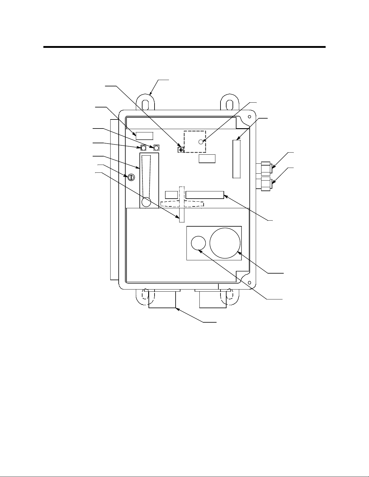
Description
Flow Adjust
Potentiometer
This section describes the components of the sample-draw detector. The sample-draw
detector consists of the housing, flow system, and detection system.
Mounting
Foot, 4X
Pump/Flow Switch
Terminal Block
Fail LED
Pilot LED
Flowmeter
Bypa ss Valve
Hydrophobic
Filter
Fl ow A l ar m Se tpoi nt
Adjustm ent Scre w.
Detector Terminal
Strip
Exhaust
Fitting
Inlet
Fitting
External
Wiring
Terminal
Strip
Oxygen
Detector
Figure 1: Sample-Draw Detector Component Location
Housing
The sample-draw detector’s fibe rglass housing is weather- and corrosion-resistant. It is
suitable for installation where general purpose equipment is in use.
The housing door is hinged on the left side and is secured by two latches on the right side.
The flowmeter and status lights are visible through a window in the housing door.
Four mounting feet are attached to the back of the housing (one at each corner). Use the
mounting feet to install the housing to a vertical surface. Use the two conduit hubs on the
bottom of the housing to make wi ri ng connections to a gas monitoring controller.
An aluminum subpanel is mounted to th e interior of the housing. The sample-draw
detector’s internal components are mounted to the subpanel.
2 • 35-3000RK-LEL/O Sample-D raw Detector
Combustible
Gas
Detector
3/4" Condui t Hub,
2X
Page 7
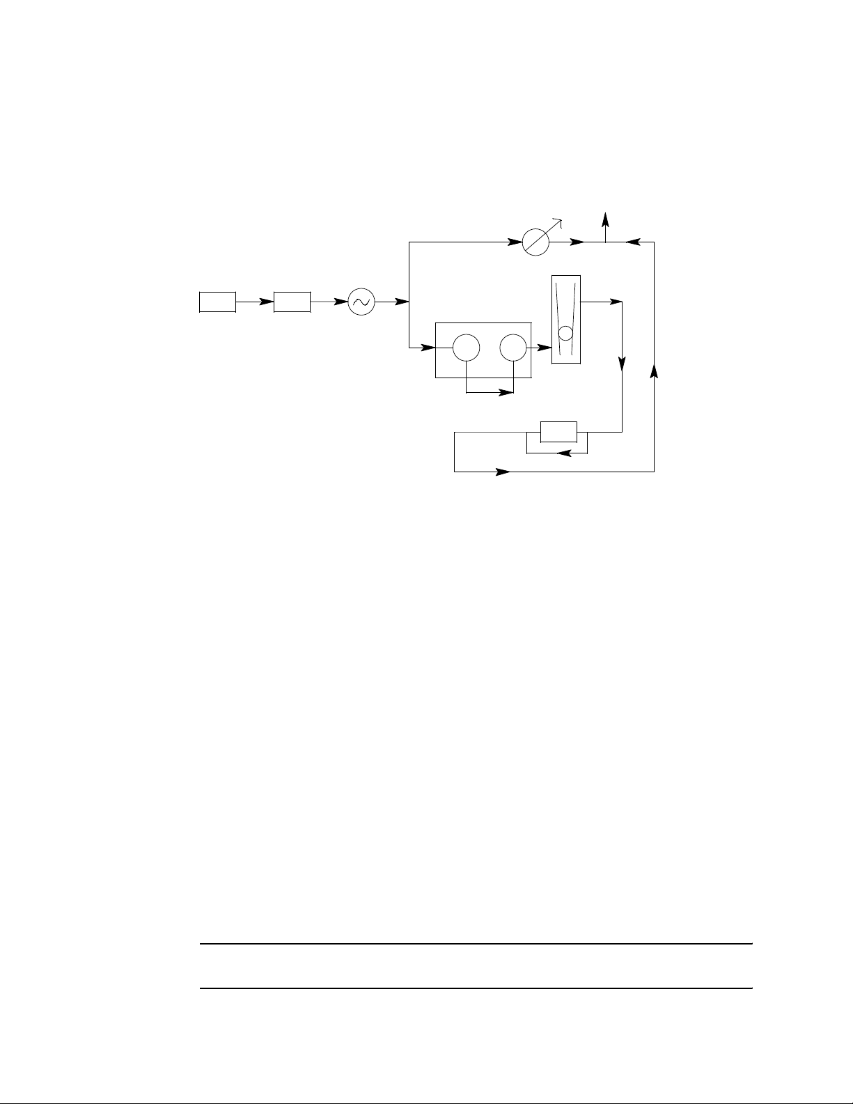
Flow System
The sample-draw detector’s flow system consists of the INLET fitting, hydrophobic filter,
pump, flowmeter, bypass valve, status lights, pressure switch, flow block, and EXHAUST
fitting (see Figure 1). Figure 2 illustrates how the gas sample moves through the flow
system.
Bypass
Valve
To Exhaust
Flow Block
Combustible Oxy
Flowmeter
Pressure Swit ch
Inlet
Hydrophobic
Filter
Pump
Figure 2: Sample-Draw Detector Flow Diagram
INLET Fitt i n g
The INLET fitting on the right side of the housing allows the gas sample to enter the
sample-draw detector. The INLET fitting accepts 1/4 in. rigid tubing. See the Insta llation
section on page 7 to connect tubing to the INLET fitting.
Hydrophobic Filter
The hydrophobic filter is below the main circuit board. The filter pre vents particulates and
water in the incoming gas sample from damaging the flow and detection systems. Replace
the filter when it appears dirty, discolored, or clogged.
Pump
The pump is behind the main circuit board near the top of the sample-draw detector.
The pump pulls the gas sample into the sample-draw detector. The pump operates on
24 VAC, which is generated from the 24 VDC supp lied by the controller.
Flowmeter
The flowmeter is attached to the main circuit board near the top left corner (see Figure 1).
You can see it through the window in the door. A ball in the flowmeter column indicates
the flow rate of the sample-draw detector. The flowmeter measures the flow in the range
0.2 to 2.0 SCFH (Standard Cubic Feet per Hour). The optimum flow rate is 1.5 SCFH.
Bypass Valve
The bypass valve is to the left of the flowmeter. The bypass valve adjusts the flow rate to
the detector. Use a flat-bla de screwdriver to adjust the bypass valve.
NOTE: The bypass valve allows fine adjustments of the flow rate. For a wider range of
adjustment, use the flow adjust potentiometer (see Figure 1).
35-3000RK-LEL/O Sample-Draw De te c to r • 3
Page 8

Status Lights
Two status lights are above the flowmeter. They are also visible through the window in
the housing door.
Pilot light
The green Pilot light is on when the sample-draw detector is receiving power from the
controller.
Fail light
The red Fail light is on when the sample flow rate is below the low flow level.
NOTE: The factory set low flow level is 0.6 SCFH (±0.2). See “Adjusting the Low Flow
Setting” on page 15 to adjust this setting.
Pressure Switch
The pressure switch is mounted to the opposite side of the main circuit board. The
pressure switch monitors the flow rate of the incoming gas sample.
If the flow rate falls below the preset low flow level, the pressure switch causes the fail
relay to interrupt the signal from the combustible gas detector. The interrupted detector
signal causes a fail condition at the controller on the combustible channel. The low flow
level is factory-set at 0.6 SCFH (±0.2 SCFH ).
NOTE: There is no low flow alarm for the oxygen sensor.
Flow Block
The flow block is located in the lower right corner of the sample-draw detector. Both
sensors are installed in the flow block. The flow block routes the sampled air to each
sensor.
EXHAUST Fitting
The EXHAUST fitting on the right side of the housin g allows the gas sample to exit the
sample-draw detector. The EXHAUST fitting accepts 1/4 in. rigid tubing. See the
Installation section on page 7 to connect tubing to the EXHAUST fitting.
Detection System
The detection system consists of the combustible gas sensor , the oxygen sensor, and the
main circuit board.
Combustible Gas Sensor
The combustible gas sensor is installed in the flow block. The combustibl e gas sensor
includes the sensing elements, flame arrestor, connector, and sensor leads.
Sensing elements
Two sensing elements are protected within the sensor assembly. Through a series of
thermal and electronic reactions, these elements produce an electrical output that is
proportional to the detection range of the sample-draw detector.
Flame arrestor
The porous flame arrestor allows the gas sample to enter the sensor assembly and contact
the sensing elements. The flame arrestor also contains any sparks that may occur within
the sensor.
4 • 35-3000RK-LEL/O Sample-D raw Detector
Page 9

Connector
The top of the sensor includes five pins that plug into the socket connector. This connector
allows you to replace the sensor without disconnecting the wiring. The sensor leads are
soldered to the connector.
Sensor leads
Four color-coded leads extend from the connector. The leads allow you to connect the
combustible gas sensor to the main circuit board.
Oxygen Sensor
The oxygen sensor is installed in the flow block to the right of the combustible gas sensor.
The oxygen sensor includes the oxy gen cell, connector, and sensor leads.
Oxygen cell
The oxygen cell is protected within the sensor assembly . Thr o ugh a series of chemical and
electronic reactions, the cell produces a millivolt output that is proportional to the
detection range of the sample-draw detector.
Connector
The cable that extends from the sensor terminates in a 7-position socket that connects to a
mating 7-pin male connector. The socket and connector allow you to replace the sensor
without disconnecting the wiring. The sensor leads are soldered to the male connector.
Sensor leads
Two color-coded leads extend from the connector. The leads allow you to connect the
oxygen sensor to the main circuit board.
Main Circuit Board
The main circuit board includes the interconnect terminal strip, detector terminal strip,
pump terminal strip, and relay (see Figure 1).
NOTE: The flowmeter and status lights are mounted to the main circuit board but are
considered part of the flow system.
Interconnect terminal strip
The interconnect terminal strip is the nine-point terminal strip near the bottom edge of the
main circuit board. Use the interconnect terminal strip to connect the sample-draw
detector to a controller.
Detector terminal str ip
The detector terminal strip is the nine-point terminal strip near the right edge of the circuit
board. Use the detector terminal strip to connect the combustible gas sensor and the
oxygen sensor to the main circuit board.
NOTE: The combustible gas sensor and oxygen sensor are factory-wired to the circuit
board. See the “Installation” section on page 7 for all wiring procedures related
to the sample-draw detector.
Pump terminal strip
The pump terminal strip is the four-point terminal strip near the top edge of the circuit
board. Use the pump terminal strip to connect the pump and pressure switch to the main
circuit board.
35-3000RK-LEL/O Sample-Draw De te c to r • 5
Page 10

NOTE: The pump and pressure switch are factory-wired to the circuit board. See
“Installation” on page 7 for all wiring procedures related to the sample-draw
detector.
Relay
The relay is to the left of the detector terminal strip. The relay is single-pole, double-throw
(SPDT) and is rated for 2 amps at 25 VDC (resistive). If the pressure switch senses a low
flow condition, the relay interrupts the signal from the combustible gas sensor. The
interrupted sensor signal causes a fail condition at the controller for the combustible gas
channel.
W ARNING: The relay will not interrupt the signal from the oxygen sensor so the oxygen
channel at the controller will not indicate a fail cond ition in the event of
low flow.
6 • 35-3000RK-LEL/O Sample-D raw Detector
Page 11

Installation
This section describes procedures to mount the sample-draw detector in the monito ring
environment and wire the sample-draw detector to a controller.
Mounting the Sample-Draw Detector
1. Select the mounting site. Consider the following when you select the mounting site.
• Is there enough room to open the housing door and make wiring connections at
the bottom of the housing and tubing connections at the right of the housing?
• Make sure there is sufficient room to perform start-up, maintenance, and
calibration procedures.
• Are the flowmeter and status lights visible?
7.3 in.
6.5 in.
4.0 in.
8.5
in.
8.9
in.
9.3
in.
Note: The housing is 4.25 in. deep.
Figure 3: Mounting the Sample-Draw D etector
4. Close and latch the housing door.
3/4 in. conduit hub
(total of 2 hubs)
NOTE: The sample-draw detector is shipped with the mounting feet “tucked under” the
housing to protect the mounting feet during shipment.
35-3000RK-LEL/O Sample-Draw De te c to r • 7
Page 12

5. Slightly loo sen the screw that secures the mounting foot to the housing, then rotate
the mounting foot 180 degrees (see Figure 3).
6. Tighten the screw that secures the mounting foot to the housing.
7. Repeat steps 3 and 4 for the remaining three mounting feet.
8. Position the sample-draw housing on a ve rtical surfac e at eye level (4 1/2 to 5 feet
from the floor).
9. Insert 1/4 inch or 5/16 inch screws through the slots in the mounting feet to secure
the housing to the mounting surface.
Connecting the Sample Lines to the Sample-Draw Detector
1. Attach 1/4 in. metal or rigid plastic sample tubing to the INLET fitting. Brass tubing is
recommended for most applications. If tubing corrosion caused by the air being
sampled is a concern, stain less steel tubing or rigid polypropylene tubing ma y be
used.
CAUTION: If you use flexible sample tubing (polyurethane for example), use an appropriate
metal insert to seal the connection be tween the tubing and the INLET fittin g. See the
Parts List at the end of this manual, for an example of an appropriate metal insert.
2. Place the opposite end of the tubi ng at the sampling area.
CAUTION: Avoid loops or slumps in the incoming sample line. T o r educe response time, keep the
incoming sample line as short as possibl e.
3. Attach rigid sample tubing to the EXHAUST fitting.
4. Route the opposite end of the tubing to an open area where the sample can safely
disperse.
Wiring the Sample-Draw Detector to a Controller
WARNING: Always verify that the controller is off and that power to the controller is
off before you make wiring connections.
1. Turn off the controller.
2. Turn off power to the controller.
3. Unlatch and open the housing door of the sample-draw de tector.
4. Guide an eight-conductor, shielded cable or eight wires in conduit through one of the
conduit hubs at the bottom of the sam p le-dra w housing.
5. Connect the cable to the sample-draw detector’s interconnect terminal strip as shown
in Figure 4.
6. Close and latch the housing door of the sample-draw detector.
CAUTION: If using shielded cable, leave the cable shield’s drain wire insulated and disconnected
at the sample-draw detec tor. You will connect the opposite end of the drain wire at
the controller.
7. Route the cable or wires in conduit leading from the sample-draw detector through
one of the conduit hubs at the controller.
8 • 35-3000RK-LEL/O Sample-D raw Detector
Page 13

CAUTION: Do not route controller power wiring and detector wiring through the same hub.
The power cable may disrupt the transmission of th e sensor signal to t he controller.
8. Connect the wires to the applicable detector terminal strip and power terminals at the
controller as shown in Figure 4. See the 35-3000RK-LEL/ O detector head specification
sheet for your controller for the specific wiring connections to the controller.
LEL/OxygenSample Draw H ousing
PUMP ASSY
INTERN ALLY
WIRED.
PUM P
PSW
PRESSURE
SWIT CH
INTERN ALLY
WIRED.
To oxygen
sensor
ControllerLEL
Detector Terminals
Red
White
Green
Black
NOT USE D
ON THIS
VERSIO N.
CG N D
NH
115VAC
PCB IN SINGLE POINT
SAMPLE DRAWING
DETE CTOR ASSY.
RD
BLKGRNWHT 4/20
24VGND
Green
White
_
+
P- A MPAMPLEL/ O2
To LEL
Sensor
BLA CK
GREEN
WHITE
RE D
_
P- AMP
+
4/20GRN B LK GND 24V
AMP
LEL/ O2
RD WHT
Controller Term inals
- (DC Groun d)
+24 VDC
Controller Oxygen
Detector Terminals
White (+)
Green (-)
Figure 4: Wiring the S ample-Draw Det ec tor to a Control ler
5. If shielded cable is used, connect the cable’s drain wire to an available chassis (earth)
ground at the controller. RKI controllers typically have a ground stud that can be used
to ground the cable’s drain wire.
35-3000RK-LEL/O Sample-Draw De te c to r • 9
Page 14

Start Up
This section describes procedures to start up the sample-draw detector and place t he
sample-draw detector into normal operation.
Introducing Incoming Power
1. Complete the installation procedures described earlier in this manual.
2. Verify that the wiring is correct and secure. Refer to the controller operator’s manual
for connections at the controller.
3. Turn on or plug in the power to the controller, then turn on the controller.
4. Ve ri fy that the sample-draw detector’s PILOT light is on.
5. Ve rify that the controller is on and operating properly. Refer to the controller
operator’s ma nual.
6. Verify that the flowmeter indicates a flow rate of approximately 1.5 SCFH. If
necessary, use the bypass valve or flow adjust potentiom eter to adjust the flow rate.
NOTE: The following step tests for leaks in the samp le line. This test will cause a low
flow condition at the sampl e-draw detector and a fail condition at the controller
on the combustible gas channel. Be sure to put the controller into its calibration
program or disable external alarms before performing this test.
7. Ve rify that the incoming sample line is not leaking. To test the sample line, plug the
open end of the sample line with your thumb. If the flowmeter ball drops to the
bottom of the flowmeter, the incoming sample line is not leaking.
8. Remove your thumb from the sample line and verify that the flowmeter returns to a
normal flow rate.
9. Enable alarms or place the controller in normal operation.
CAUTION: Allow the sample-draw detector to warm up for 15 minutes before you continue with
the next section, “Setting the Zero/Fresh Air Re ading”.
Setting the Zero/Fresh Air Reading
CAUTION: If you suspect the presence of combustible gas or an abnormal oxygen concentration
in the monitoring environment, use the calibration kit and th e zero air calibration
cylinder to introduce “fresh ai r” to the sensor and verify an accurate zero setting.
See the Calibration section of this manual for instructions on using a zero air
calibration cylinder for setting the zero reading.
1. Verify that the sample-draw detector is sampling a fresh air environment
(environment known to be free of combustible gas and of normal oxygen
concentration, 20.9%).
2. Verify a reading of 0 %LEL for the combustible channel and 20.9% for the oxygen
channel on the controller display screen for the applicable channel.
If the display reading is 0 % LEL for the combustible channel and 20.9% for the
oxygen channel, start up is complete. The sample-d raw detector is in normal
operation. If the display reading is not 0 % LEL for the combustible channel or 20.9%
10 • 35-3000RK-LEL/O Sample- Draw Detector
Page 15

3. Perform a zero operation at the controller. See the controller operator’s manual for
Maintenance
This section describes maintenance procedures. It includes preventive maintenance
procedures. This section also includes procedures to troubleshoot the sample-draw
detector, replace components of the sample-draw detector, and adjust the low flow
setting.
Preventive Maintenance
This section describes a preventive maintenance schedule to ensure the optimum
performance of the sample-draw detector. It includes daily, monthly, and quarterly
procedures.
Monthly Visual Checks
1. Verify that the pilot light is on.
2. Verify that the f lowmeter indicates a flow rate of approximately 1.5 SCFH.
for the oxygen channel, continue with step 3.
instructions to perform a zero operation.
If necessary use the bypass valve or flow ad just potentiometer to adjust the flow rate
to 1.5 SCFH.
3. Verify a display reading of 0 %LEL for the combustible channel and 20.9% for the
oxygen channel at the controller. Investigate significant changes in the display
reading.
Monthly Response Test
This pr oc edure describes a test to verify that the sample-draw detector responds properly
to the target gas.
NOTE: To reduce the response time of this test, use a short incoming sample line. If the
sample-draw detector’s sample line is long, connect a shorter line for this test.
Make sure you reconnect the sample line after you complete this procedure.
NOTE: Performing a response test on the sample-draw detector may cause alarms. Be
sure to put the controller into its calibration program or disable external alarms
before performing this test.
Preparing for the response test
NOTE: This procedure describes the RKI calibration kit that includes a demand flow
regulator.
1. V erif y that the display readi ng at the contro ller is 0 % LEL for the combustible chan nel
and 20.9% for t he oxygen channel.
If the display reading is not 0 % LEL for the combustible chan nel or 20.9% for the
oxygen channel, set the zero reading as described in the Calibration section, then
continue this procedure.
35-3000RK-LEL/O Sample-Draw Det ec t or • 1 1
Page 16

Performing the response test
1. Screw the demand flow regulator into the combustible gas calibration cylinder.
2. Connect the calibration tubing from the regulator to the INLET fitting. Gas will begin
to flow.
3. After approximately one minute, verify tha t the reading at the controller stabilizes
within ± 20% of the concentration of the test sample. If the reading is not within ± 20%
of the test sample, calibrate the sample-draw detector as described in the Calibration
section.
4. Remove the calibration tubing from the INLET fitting.
5. Store the calibration kit in a safe place.
6. Exhale into the sample-draw detector’s INLET fitting.
7. Stop exhaling in to the sample line, then verify that the readings at the controller
decreased.
8. If the reading does not decrease, calibrate the sample draw detector as described in
the Calibration section.
9. Reconnect the incoming sample line to the INLET fitting.
Quarterly Calibration
Calibrate the sample-draw detector as described in the Calibration section.
Troubleshooting
The troubleshooting guide describes symptoms, probable causes, and recommended
action for problems you may encounter with the sample-draw detector.
NOTE: This troubleshooting guide describes sample-draw detector problems only. See
the controller operator’s manual if the controller exhibits any problems.
Fail Condition
Symptoms
• The sample-draw detector’s Fail light is on.
• The monitoring devic e is operating properly but ind icates a reading well below zero.
Probable causes
• The sample-draw detector’s flow rate is too low because of an obstructed sample line,
failed pump, etc.
• The sample-draw detector is malfunction ing.
• The sensor wiring is disconnected or misconnected.
Recommended action
1. At the sample-draw detector, set the correct flow rate with the bypass valve or flow
adjust potentiometer.
2. If you cannot set the correct flow rate, check the sample lines for obstructions or kinks.
3. V erify that the sensor wiring is correct and secure. “W iring the Sample-Draw Detector
to a Controller” on page 8 describes sens or wiring connections.
4. Calibrate the sample-draw detector as described in the Calibration section.
5. If the fail condition continues, replace the sensors as described later in this section.
12 • 35-3000RK-LEL/O Sample- Draw Detector
Page 17

6. If the fail condition continues, contact RKI Instruments, Inc. for further instruction.
Slow or No Response/Difficult or Unable to Calibrate
Symptoms
• The sensors respond slowly or d o not respond during the monthly response test.
• Unable to accurately set the zero or response reading during the calibration
procedure.
• The sensors require frequent calibration.
Probable causes
• The calibration cylinder is low, out-dated, or defective.
• If a demand flow regulator calibration kit is used, the demand flow regulator is not
functioning properly.
• The sample-draw detector’s flow rate is too low because of an obstructed sample line,
failed pump, etc.
• The sample-draw detector is malfunction ing.
Recommended action
1. Verify that the calibration cylinder contai ns an adequate supply of a fresh test sample.
2. If a demand flow regulator calibration kit is used, use a different demand flow
regulator to determine if the original one is functioning properly.
3. If necessary, set the correct flow rate with the bypass valve or flow adjust
potentiometer.
4. If you cannot set the correct flow rate, check the sample lin e for obstructions or kinks.
5. If the calibration/response difficulties continue, replace the sensors as described later
in this section.
6. If the calibrat ion/response difficulties continue, contact RKI Instruments, Inc. for
further instruction.
Replacing Components of the Sample-Draw Detector
This section includes procedures to replace the sensors, hydrophobic filt er, and ferrules.
Replacing the Combustible Gas Sensor
1. Turn off the controller
2. Turn off power to the controller.
3. Open the housing door of the sample-draw detector.
4. Unscrew and remove the two screws that secure the sensor retaining plate, then lift
the plate, connector, and sensor out of the housing.
5. Unplug the connector from the sensor.
6. Verify tha t you are using the correct replacement sensor (NC-6240 is printed on the
sensor), then plug the sensor into the conn ector.
7. Place the sensor in the combustible gas sensor cavity, then position the retaining plate
on the two standoffs.
8. Secure the retaining plate to the standoffs with the two screws you removed in step 4.
9. Close and latch the housing door.
10. Turn on power to the con troller.
35-3000RK-LEL/O Sample-Draw Det ec t or • 1 3
Page 18

11. Turn on the controller.
CAUTION: Allow the replacement sensor to warm up for 15 m inut es before you continue.
12. Calibrate the replacement sensor as described in “Calibration, Combustible Sensor”
on page 16.
Replacing the Oxygen Sensor
1. Turn off the controller.
2. Turn off power to the controller.
3. Open the housing door of the sample-draw detector.
4. Unscrew and remove the two screws that secure the sensor retaining plate, then lift
the plate, connector, and sensor out of the housing.
5. Unplug the connector from the sensor cable socket.
6. Plug the socket of the replacement sensor into the connector.
7. Place the sensor in the oxygen sensor cavity, then po sition the retaining plate on the
two standoffs.
8. Secure the retaining plate to the standoffs with the two screws you removed in step 4.
9. Turn on power to the controller.
10. Turn on the controller.
11. Calibrate the replacement sensor as described in “Calibration, Oxygen Sensor” on
page 17.
Replacing the Filter
1. Open the housing door of the sample-draw detector.
2. Disconnect the filter from the rubber elbows on each end of the filter, then remove the
filter from the sample-draw detector.
3. Install the new filter.
4. Verify that the flow rate is approximately 1.5 SCFH, then close the housing door.
Replacing the Ferrules
The INLET and EXHAUST fittings each includes two ferrules that seal the inlet or exhaust
tubing to the fitting. Replace the ferrules if the seal is bad or if you replace the sample
tubing. Always replace the ferrules as a pair.
1. Unscrew the nut that holds the tubing to the fitting from the fitting.
2. Slide the nut away from the end of the tubing.
3. Cut off the end of the sample tube with the old ferrules off about one inch from the
end.
4. Slide the nut off the sample tubing.
5. Position the nut so the threaded end is facing you, then insert the bottom (smaller)
ferrule into the nut. Insert the ferrule so the flat side is facing down.
NOTE: Make sure the bottom ferrule is laying flat in the nut.
14 • 35-3000RK-LEL/O Sample- Draw Detector
Page 19

6. Insert the cone-shaped front ferrule on top of the bottom ferrule. Insert the ferrule so
the smaller end of the cone is facing up.
7. Screw the nut onto the fitting by hand jus t until it stops turning.
8. Insert the sample tubing into the fitting until it bottoms out.
9. Firmly tighten the nut so the ferrules crimp onto the sample tubing and make a seal.
Adjusting the Low Flow Setting
NOTE: Adjusting the low flow setting will cause a low flow alarm at the sample-draw
detector and a fail alarm at the controller on the combustible channel. Be sure to
put the controller into its calibration program or disable external alarms before
performing this test.
The factory-set low flow setting is 0.6 SCFH (±0.2). To adjust the low flow setting:
1. Use the flow adjust potentiometer (VR1) to set the f low to 0.6 SCFH.
If the sample-draw detector goes into low f low alarm before you can adjust the flow
down to 0.6 SCFH, adjust the low flow potentiometer 1/4 turn clockwise, then
attempt to set the flow again. Repeat this step until you are able to adjust the flow to
0.6 SCFH.
NOTE: The low flow potentiometer is accessible through a circular cutout in the main
circuit board. The cutout is labeled PS1.
2. Slowly turn the low flow potentiometer counterclockwise just until the sample-draw
detector goes into low flow alarm.
3. Increase the flow using VR1 until the unit is out of low flow alarm.
4. Decrease the flow very slow ly and verify that the low flow alarm is 0.6 SCFH (±0.2).
If the low flow alarm is set too low, turn the low flow potentiometer slightly
clockwise. Repeat steps 3 and 4 if necessary.
5. Use the flow adjust potentiometer (VR1) to set the f low to 1.5 SCFH.
6. Make sure the sample-draw detector’s Fail light is off.
Calibration Frequency
Although there is no particular calibration frequency that is correct for all sample draw
detector applications, a calibration frequency of every 3 to 6 months is adequate for most
applications. Unless experience in a particular application dictates otherwise, RKI
Instruments, Inc. recommends a calibration frequency of every 3 months.
If an application is not very demanding, for example detection in a clean, temperature
controlled environment where combustible gases ar e not normally present and calibration
adjustments are minimal at calibration, then a calibration frequency of every 6 months is
adequate.
If an application is very demanding, for example if combustible gases are present often
and in significant concentrations or the environment is not well controlled, then more
frequent calibration than every 3 months may be necessary.
35-3000RK-LEL/O Sample-Draw Det ec t or • 1 5
Page 20

Calibration, Combustible Sensor
This section describes how to calibrate the combustible sensor in the sample-draw
detector. It includes procedures to prepare for calibration, set the zero reading, set the
response reading, and return to nor mal operation.
The standard calibration gas for the sample-draw detector is methane. The sample-draw
detector may be calibrated to other combustible gases such as hexane or hydrogen. Use
the correct calibration gas for your installation.
NOTE: Calibrating the sample-draw detector may cause alarms. Be sure to put the
controller into its calibration program or disable external alarms before
continuing.
NOTE: This procedure describes calibration using a demand flow regulator.
Prepari ng for Ca libration
NOTE: If you can verify a fresh air environment, it is not necessary to use the zero air
calibration cylinder to set the zero reading.
1. Follow the instructions in the controller’s operator’s manu al for entering calibration
mode.
2. Screw the regulator into a zero air calibration cylinder.
Setting the Zero Reading
1. Connect the sample tubing from the demand flow regulator to the sample-draw
detector’s inlet line. This step is not necessa ry if you verifie d a fresh air
environment earlier in this procedure.
2. Allow the sample-draw detector to draw sample for one minute.
3. Follow the directions in the controller ’s operator’s manual for setting the zero
reading. If you used a zero air calibration cylinder to set the zero reading, proceed to
step 4. If you verified a fresh air environment, proceed to the next section, Setting the
Response Read ing.
4. Disconnect the sample tubi ng from the inlet line.
5. Unscrew the regulator from the zero air calibration cylin d er.
Setting the Response Reading
1. Screw the regulator into the combustible gas calibration cylinder.
2. Connect the sample tubing from the demand flow regulator to the sample-draw
detector’s inlet line.
3. Allow the sample-draw detector to draw sample for one minute.
4. Follow the directions in the controller ’s operator’s manual for setting the span.
5. Disconnect the sample tubi ng from the inlet fitting.
6. Unscrew the regulator from the combustible gas calibration cylinder.
16 • 35-3000RK-LEL/O Sample- Draw Detector
Page 21

Returning to Normal Operation
1. Reconnect the incoming sample line.
2. Wait approximately one minute to allow the combustible gas reading to stabilize.
3. Follow the instructions in the controller’s operator’s manu al to exit the calibration
mode.
4. Store the components of the calibration kit in a safe and convenient place.
Calibration, Oxygen Sensor
This section describes how to calibrate the oxygen sensor in the sample-draw detector. It
includes procedures to prepare for calibration, set the fresh air reading, set the zero
reading, and return to normal operation.
NOTE: Calibrating the sample draw detector may cause alarms. Be sure to put the
controller into its calibration program or disable external alarms before
continuing.
NOTE: This procedure describes calibration using a demand flow regulator.
Prepari ng for Ca libration
NOTE: If you can verify a fresh air environment, it is not necessary to use a zero air
calibrating sample to set the fresh air reading at the controller.
1. Follow the instructions in the controller’s operator’s manu al for entering calibration
mode.
2. Screw the regulator into the zero air calibration cylind er.
Setting the Fresh Air Reading
1. Connect the sample tubing from the demand flow regulator to the sample-draw
detector’s inlet fitting. This step is not necessary if you verified a fresh air
environment earlier in this procedure.
2. Allow the sample draw detector to draw sample for one minute.
3. Follow the directions in the controller’s operator’s manual for setting the fresh air
reading.
4. Disconnect the sample tubi ng from the inlet fitting.
5. Unscrew the regulator from the zero air calibration cylin d er.
Setting the Zero Reading
1. Screw the demand flow regulator onto the 100% N2 calibration cylinder.
2. Connect the sample tubing from the regulator to the inlet line.
3. Allow the sample-draw detector to draw the ca librating sample for 1 minute.
4. Follow the directions in the controller ’s operator’s manual for setting the zero
(oxygen free) reading.
35-3000RK-LEL/O Sample-Draw Det ec t or • 1 7
Page 22

5. Disconnect the sample tubi ng from the sample-draw detector’s inlet fitting.
6. Reconnect the incoming sample line to the inlet fitting.
7. Unscrew the regulator from the calibration cylinder.
Returning to Normal Operation
1. Wait 1 to 2 minutes to allow the oxygen reading at the controller to return to normal,
then return the controller to normal operation.
NOTE: If you do not allow the oxygen reading to return to normal, then unwanted
alarms may occur.
2. Verify that the controller display reading stabilizes at 20.9%.
3. Store the components of the calibration kit in a safe and convenient place.
18 • 35-3000RK-LEL/O Sample- Draw Detector
Page 23

Parts List
Table 2 lists replacement parts and accessories for the sample-draw detector.
Table 2: Parts List
Part Number Description
06-1248RK Sample tubing, 3/16 x 5/16, specify length, (for calibration kit)
17-2593RK Brass insert for flexible 1/4 OD x .17 ID tubing (for INLET and EXHAUST fit-
tings)
17-2683RK Front ferrule (for INLET and EXHAUST fittings)
17-2688RK Back ferrule (for INLET and EXHAUST fittings)
30-0610RK Pump
33-0165RK Hydrophobic filter
61-0145RK Com bustible gas sensor, plug-in type, LEL range
65-0601RK Oxygen sensor (plug-in type)
71-0223RK Operator’s Manual, 35-3000RK-LEL/O Sample-Draw Detector (this document)
81-0002RK-01 Calibration cylinder, 50% LEL hydrogen in air 34 liter)
81-0002RK-03 Calibration cylinder, 50% LEL hydrog en in a ir, 103 liter
81-0007RK-01 Calibration cylinder, 50% LEL hexane in air, 34 liter
81-0012RK-01 Calibration cylinder, 50% LEL methane in air, 34 liter
81-0012RK-03 Calibration cylinder, 50% LEL methane in air 103 liter)
81-0076RK-01 Zero air calibration cylinder (34 liter)
81-0076RK-03 Zero air calibration cylinder (103 liter)
81-0078RK Calibration cylinder (100% Nitrogen; 17 liter)
81-0078RK-01 Calibration cylin der (100% Nitrogen; 34 liter)
81-0078RK-03 Calibration cylinder (100% Nitrogen; 103 liter)
81-1054RK Regulator (demand flow), for 58 and 103 liter steel calibration cylinders
81-1055RK Regulator (d emand flow), for 17 and 34 liter steel calibration cylinders
35-3000RK-LEL/O Sample-Draw Det ec t or • 1 9
 Loading...