

Page 1

±
±
35-3000RKA-LEL Sample Draw Combustible Gas
Detector
Specifications
Table 1 lists specifications for the sample draw combustible gas detector.
Table 1: Specifications
Target Gas Combustible Gas
Input Power 24 VDC
Construction (housing) Fiberglass/polyester (NEMA 4X)
Dimensions 8.5 in. H x 6.5 in. W x 4.25 in. D
Weight 4.5 lbs.
Sampling Method sample draw
Sample Flow 1.5 SCFH (nominal)
Detection Range 0 to 100% LEL
Response Time 90% in 30 seconds
Linearity
Repeatability
5% of detection range
2% of detection range
Sample Draw Combustible Gas Detector • 1
Page 2
O
Description
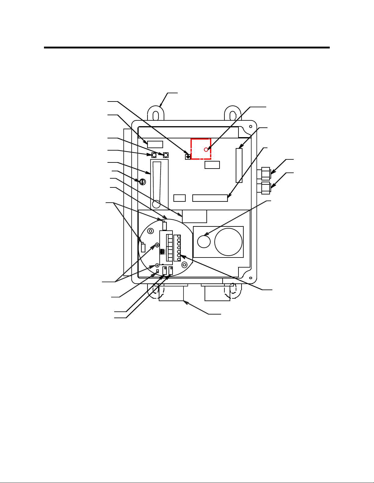
This section describes the components of the sample draw combustible gas detector. The
sample draw detector consists of the housing, flow system, and detection system.
Mounting
Flow Adjust
Potentiometer
Pu mp /flo w sw itch
terminal block
Fail LED
Pilot LED
Flowmeter
Bypass valve
Particle filter
LE L Transmitter
Foot, 4X
Flow Alarm Setpoint
Adjustment Potentiometer
Se nso r Wiring
Terminal St rip
External Wiring
Terminal Strip
Exhaust
Inlet
Factory Set Pots
Test Points
100 - 500 mV range
JUMPER PINS FOR
FACTORY U SE ONLY
Span Pot
Zero Pot
Housing
The sample draw detector’s fiberglass housing is weather- and corrosion-resistant. It is
suitable for installation where general purpose equipment is in use.
LEL
sensor
P/N 57-1050RK
REV. 0
GND
24V
TP +
4-20
POWER/SIG
RED
WHT
SENSOR
GRN
BLK
ZER
SPAN
TP
Terminal Block
3/4" Conduit
Hub, 2X
Figure 1: Sample draw Combustible Gas Detector Component Location
The housing door is hinged on the left side and is secured by two latches on the right side.
The flowmeter and status lights are visible through a window in the housing door.
Four mounting feet are attached to the back of the housing (one at each corner). Use the
mounting feet to install the housing to a vertical surface. Use the two conduit hubs on the
bottom of the housing to make wiring connections.
An aluminum subpanel is mounted to the interior of the housing. The sample draw
detector’s internal components are mounted to the subpanel.
2 • Sample Draw Combustible Gas Detector
Page 3
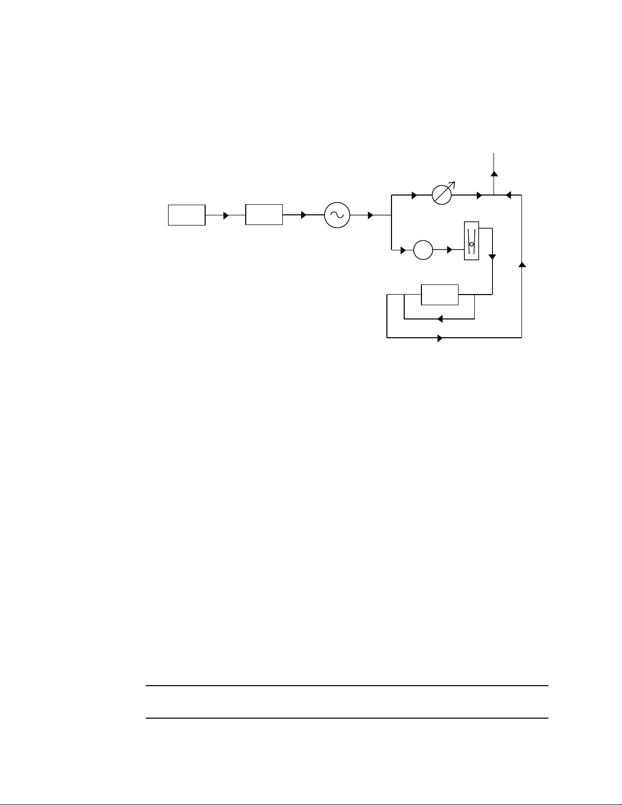
Flow System
The sample draw detector’s flow system consists of the INLET fitting, filter, pump,
flowmeter, bypass valve, status lights, pressure switch, and EXHAUST fitting (see
Figure 1). Figure 2 illustrates how the gas sample moves through the flow system.
To
Exhaust
Bypass
Valve
Flowmeter
Inlet Filter Pump Sensor
Pressure Switch
Figure 2: Sample draw Combustible Gas Detector Flow Diagram
INLET fitting
The INLET fitting on the right side of the housing allows the gas sample to enter the
sample draw detector. The INLET fitting accepts 1/4 in. rigid tubing. See the Installation
section on page 7 to connect tubing to the INLET fitting.
Filter
The dust filter is below the main circuit board. The filter prevents particulates in the
incoming gas sample from damaging the flow and detection systems. Replace the filter
when it appears dirty, discolored, or clogged.
Pump
The pump is behind the main circuit board near the top of the sample draw detector.
The pump pulls the gas sample into the sample draw detector. The pump operates on
24 VAC, which is generated from the 24 VDC supplied to the sample draw detector.
Flowmeter
The flowmeter is attached to the main circuit board near the top left corner (see Figure 1.)
You can see it through the window in the door. A ball in the flowmeter column indicates
the flow rate of the sample draw detector. The flowmeter measures the flow in the range
0.2 to 2.0 SCFH (Standard Cubic Feet per Hour). The optimum flow rate is 1.5 SCFH.
Bypass valve
The bypass valve is to the left of the flowmeter. The bypass valve adjusts the flow rate to
the sensor. Use a flat-blade screwdriver to adjust the bypass valve.
NOTE: The bypass valve allows fine adjustments of the flow rate. For a wider range of
adjustment, use the flow adjust potentiometer (see Figure 1.)
Sample Draw Combustible Gas Detector • 3
Page 4

Status lights
Two status lights are above the flowmeter. They are also visible through the window in
the housing door.
Pilot light
The green Pilot light is on when the sample draw detector is receiving power.
Fail light
The red Fail light is on when the sample flow rate is below the low flow level.
NOTE: The default low flow level is 0.6 SCFH ( ± 0.2). See “Adjusting the Low Flow
Setting” on page 15 to adjust this setting.
Pressure switch
The pressure switch is mounted to the opposite side of the main circuit board. The
pressure switch monitors the flow rate of the incoming gas sample.
If the flow rate falls below the preset low flow level, the pressure switch causes the fail
relay to interrupt the signal in the 4-20 mA line. This causes a downscale reading at the
monitor. The low flow level is factory-set at 0.6 SCFH ( ± 0.2 SCFH).
EXHAUST fitting
The EXHAUST fitting on the right side of the housing allows the gas sample to exit the
sample draw detector. The EXHAUST fitting accepts 1/4 in. rigid tubing. See the
Installation section on page 7 to connect tubing to the EXHAUST fitting.
Detection System
The detection system consists of the combustible gas sensor, the hydrogen transmitter,
and the main circuit board.
Combustible gas sensor
The combustible gas sensor is installed in a cavity block. The cavity block is mounted to
the aluminum subpanel near the bottom of the sample draw detector. The combustible
gas sensor includes the sensing elements, flame arrestor, connector, and sensor leads.
NOTE: The cavity block includes a cavity for an oxygen sensor. This version of the
sample draw detector does not include the oxygen sensor.
Sensing elements
Two sensing elements are protected within the sensor assembly. Through a series of
thermal and electronic reactions, these elements produce an output that is pr oportional to
the detection range of the sample draw detector . The transmitter converts the output to a 4
- 20 mA signal which can be used by a recording or monitoring device.
The porous flame arrestor allows the gas sample to enter the sensor assembly and contact
the sensing element. The flame arrestor also contains sparks within the sensor.
4 • Sample Draw Combustible Gas Detector
Page 5

Connector
The top of the sensor includes five pins that plug into the socket connector . This connector
allows you to replace the sensor without disconnecting the wiring. The sensor leads are
soldered to the connector.
Sensor leads
Four color-coded leads extend from the connector. The leads allow you to connect the
combustible gas sensor to the main circuit board.
Transmitter
The transmitter is mounted to the left of the combustible sensor. It consists of the span
pot, zero pot, transmitter interconnect terminal strip, sensor terminal strip and test points.
Span/zero pots
The span and zero pots are located at the bottom edge of the transmitter and are used for
calibration. Use the span pot to make adjustments to gas response readings and the zero
pot to make adjustments to the zero reading
Transmitter interconnect terminal strip
The transmitter interconnect terminal strip is the six-point terminal strip near the right
edge of the transmitter. The transmitter is factory wired to the sensor and main circuit
board.
Test points
The test points are located on the left side of the transmitter and are labeled TP+ and TP- .
A 100 mV - 500 mV output is available at these testpoints for use during calibration.
Main Circuit Board
The main circuit board includes the interconnect terminal strip, transmitter terminal strip,
pump terminal strip, and relay (see Figure 1).
NOTE: The flowmeter and status lights are mounted to the main circuit board but are
considered part of the flow system.
Interconnect terminal strip
The interconnect terminal strip is the nine-point terminal strip near the bottom edge of the
main circuit board. Use the interconnect terminal strip to connect the sample draw
detector to power and external devices.
Transmitter terminal strip
The transmitter terminal strip is the nine-point terminal strip near the right edge of the
circuit board. Use the transmitter terminal strip to connect the transmitter to the main
circuit board.
NOTE: The transmitter is factory-wired to the circuit board. See the “Installation” section
on page 7 for all wiring procedures related to the sample draw detector.
Sample Draw Combustible Gas Detector • 5
Page 6

Pump terminal strip
The pump terminal strip is the four-point terminal strip near the top edge of the circuit
board. Use the pump terminal strip to connect the pump and pressure switch to the main
circuit board.
NOTE: The pump and pressure switch are factory-wired to the circuit board. See the
“Installation” on page 7 for all wiring procedures related to the sample draw
detector.
Relay
The relay is to the left of the detector terminal strip. The relay is single-pole, double-throw
(SPDT) and is rated for 2 amps at 25 VDC (resistive). If the pressure switch senses a low
flow condition, the relay interrupts the signal from the transmitter. The interrupted
transmitter signal causes a fail condition at the Pioneer.
6 • Sample Draw Combustible Gas Detector
Page 7

Installation
This section describes procedures to mount the sample draw combustible gas detector in
the monitoring environment and wire the sample draw detector to power and an external
device.
Mounting the Sample draw Combustible Gas Detector
1. Select the mounting site. Consider the following when you select the mounting site.
• Is there enough room to open the housing door and make wiring connections at
the bottom of the housing and tubing connections at the right of the housing?
Make sure there is sufficient room to perform start-up, maintenance, and
calibration procedures.
•Are the flowmeter and status lights visible?
7.3 in.
9.3
in.
6.5 in.
4.0 in.
8.5
in.
8.9
in.
3/4 in. conduit hub
(total of 2 hubs)
Note: The housing is 4.25 in. deep.
Figure 3: Mounting the Sample Draw Combustible Gas Detector
Sample Draw Combustible Gas Detector • 7
Page 8

2. Close and latch the housing door.
NOTE: The sample draw detector is shipped with the mounting feet “tucked under” the
housing to protect the mounting feet during shipment.
3. Slightly loosen the screw that secures the mounting foot to the housing, then rotate
the mounting foot 180 degrees (see Figure 3).
4. Tighten the screw that secures the mounting foot to the housing.
5. Repeat steps 3 and 4 for the remaining three mounting feet.
6. Position the sample draw housing on a vertical surface at eye level (4 1/2 to 5 feet
from the floor).
7. Insert 1/4 in. screws through the slots in the mounting feet to secure the housing to
the mounting surface.
Connecting the Sample Lines to the Sample Draw
Combustible Gas Detector
1. Attach 1/4 in. metal or plastic rigid sample tubing to the INLET fitting.
CAUTION: If you use flexible sample tubing (vinyl or polyurethane for example), use an
appropriate metal insert to seal the connection between the tubing and the INLET
fitting. See Appendix A, Parts List, for an example of an appropriate metal insert.
2. Place the opposite end of the tubing at the sampling area.
CAUTION: Avoid loops or slumps in the incoming sample line. To reduce response time, keep the
incoming sample line as short as possible.
3. Attach rigid sample tubing to the EXHAUST fitting.
4. Route the opposite end of the tubing to an open area where the sample can safely
disperse.
Wiring the Sample Draw Combustible Gas Detector
WARNING: Always verify that the power source is OFF before you make wiring
connections.
1. Unlatch and open the housing door of the sample draw detector.
2. Guide a three-conductor, shielded cable or three wires in conduit through one of the
conduit hubs at the bottom of the sample draw housing.
3. Connect the cable to the sample draw detector’s interconnect terminal strip as shown
in Figure 4.
4. Close and latch the housing door of the sample draw detector.
CAUTION: Leave the shield cable insulated and disconnected at the sample draw detector.
You will connect the opposite end of the shield cable at the device.
8 • Sample Draw Combustible Gas Detector
Page 9

5. Route the cable or wires in conduit leading from the sample draw detector to the
recording or monitoring device and power.
6. Connect the cable shield to an available chassis ground at the device end.
LEL Sample Draw Housing
Transmitter, Internally Wi red
P/N 57-1050RK
REV. 0
GND
24V
TP +
4-20
POWER/SIG
RED
WHT
GRN
SENSOR
BLK
ZEROSPAN
TP
WHITE
BLAC K
GREEN
RED
LEL DETECTOR IN
SAMPLE CHAMBER
(INTERNALLY WIRED)
PUMP ASSY
INTERNALLY
WIRED
PUM P PS W
PRES SURE SWITCH
INTERNALLY WIRED.
PCB IN SINGLE POINT
SAMPLE DRAWING
DETECTOR ASS Y
NOT
USED
ON THIS
VE RS ION
HN
115VAC
CG ND
WHT GR N
RD
LEL/O2 AMP P- AM P
GN D 2 4 V +
BLK
_
4/20
4/20 (Feedback)
24VDC
+
Gr ound
Figure 4: Wiring the Sample Draw Combustible Gas Detector
4/20
24V
GN D
Sample Draw Combustible Gas Detector • 9
Page 10

Start Up
This section describes procedures to start up the sample draw combustible gas detector
and place the sample draw detector into normal operation.
Introducing Incoming Power
1. Complete the installation procedures described earlier in this manual.
2. Verify that the power/device wiring is correct and secure.
3. Turn on or plug in the incoming power at the power source end.
4. Verify that the Pilot light is on.
5. Verify that the flowmeter indicates a flow rate of approximately 1.5 SCFH. If
necessary, use the bypass valve or flow adjust potentiometer to adjust the flow rate.
NOTE: The following step tests for leaks in the sample line. This test may cause a low
flow condition at the sample draw detector.
6. Verify that the incoming sample line is not leaking. To test the sample line, plug the
open end of the sample line with your thumb. If the flowmeter ball drops to the
bottom of the flowmeter, the incoming sample line is not leaking.
7. Remove your thumb from the sample line, verify the flowmeter returns to a normal
flow rate.
Setting the Zero Reading
CAUTION: If you suspect the presence of combustible gas in the monitoring environment, use
the calibration kit and the zero air calibration cylinder to introduce “fresh air” to the
sensor and verify an accurate zero setting.
1. Verify that the sample draw detector is sampling a fresh air environment
(environment known to be free of combustible gas).
2. Open the housing door.
3. Set a voltmeter to measure in the milivolt (mV) range.
4. Plug the voltmeter leads into the test points on the amplifier. Plug the positive lead
into the test point labeled TP+ ; plug the negative lead into the test point labeled TP- .
5. Verify a voltmeter reading of 100 mV ( ± 2 mV).
6. If necessary, use a small flat-blade screwdriver to adjust the zero potentiometer until
the voltmeter reading is 100 mV ( ± 2 mV).
7. Close the housing door.
10 • Sample Draw Combustible Gas Detector
Page 11

Maintenance
This section describes maintenance procedures. It includes preventive maintenance
procedures. This section also includes procedures to troubleshoot the sample draw
detector , r eplace components of the sample draw combustible gas detector, and adjust the
low flow setting.
Preventive Maintenance
This section describes a preventive maintenance schedule to ensure the optimum
performance of the sample draw detector. It includes daily, monthly, and quarterly
procedures.
Daily
1. Verify that the pilot light is on.
2. Verify that the flowmeter indicates a flow rate of approximately 1.5 SCFH.
3. Verify a reading of 0 %LEL (4 mA) at the monitoring device or a reading of 100 mV at
Monthly
If necessary use the bypass valve or flow adjust potentiometer to adjust the flow rate
to 1.5 SCFH.
the transmitter test points. Investigate significant changes in the reading.
This procedure describes a test to verify that the sample draw combustible gas detector
responds properly to the target gas.
Preparing for the response test
NOTE: This procedure describes the RKI calibration kit that includes a gas collection
bag. A calibration kit that uses a demand flow regulator is also available.
1. Verify that the monitoring device is reading 0 %LEL (4 mA).
If the reading is not 0, set the zero reading as described in the “Start Up” section on
page 10, then continue this procedure.
2. Connect the calibration kit sample tubing along with the tubing clamp to the fitting on
the gas collection bag.
3. Connect the sample tubing from the gas collection bag to the inlet line at or near the
INLET fitting.
Allow the sample draw pump to draw out any residual gas in the gas collection bag.
NOTE: This will cause a low flow alarm when the bag is empty. Normal operation of the
sample draw adapter will resume when the tubing is disconnected from the inlet
line.
4. Disconnect the calibration kit sample tubing from the inlet line.
5. Close the clamp right away. The clamp is attached to the calibration kit sample tubing.
6. Connect the tubing from the gas collection bag to the fixed flow regulator, then open
the clamp.
7. Screw the fixed flow regulator onto the calibration gas cylinder. The gas collection bag
begins to fill.
Sample Draw Combustible Gas Detector • 11
Page 12

8. When the bag is full, unscrew the fixed flow regulator form the cylinder.
9. Close the clamp, then disconnect the sample tubing from the fixed flow regulator.
Performing the response test
1. Connect the calibration tubing from the gas collection bag to the inlet line at or near
the INLET fitting.
The sample draw detector’s pump automatically begins pulling the test sample from
the gas collection bag when you connect the tubing to the inlet line.
2. After approximately one minute, verify that the reading at the monitoring device
stabilizes within ± 10% of the concentration of the test sample. If the reading is not
within ± 10% of the test sample, calibrate the sample draw detector as described in the
Calibration section of this manual.
3. Remove the calibration tubing from the inlet line, then reconnect the inlet line.
Quarterly
Calibrate the sample draw detector as described in the “Calibration” section on page 16.
Troubleshooting
The troubleshooting guide describes symptoms, probable causes, and recommended
action for problems you may encounter with the sample draw combustible gas detector.
NOTE: This troubleshooting guide describes sample draw detector problems only. See
the instruction manual for monitoring device if it exhibits any problems.
Fail condition
Symptoms
• The sample draw detector’s Fail light is on.
• The monitoring device is indicating a reading well below zero.
• The monitoring device is indicating a Fail condition.
Probable causes
• The sample draw detector’s flow rate is too low because of an obstructed sample line,
failed pump, etc.
• The sample draw detector is malfunctioning.
• The sensor or transmitter wiring is disconnected or misconnected.
Recommended action
1. At the sample draw detector, set the correct flow rate with the bypass valve or flow
adjust potentiometer.
2. If you cannot set the correct flow rate, check the sample lines for obstructions or kinks.
3. Verify that the detector and transmitter wiring are correct and secure. The Installation
section on page 7 describes detector wiring connections.
4. Calibrate the sample draw detector as described in the Calibration section on page 16.
5. If the fail condition continues, replace the sensor as described later in this section.
6. If the fail condition continues, contact RKI Instruments, Inc., for further instruction.
12 • Sample Draw Combustible Gas Detector
Page 13

Slow or no response/difficult or unable to calibrate
Symptoms
• The detector responds slowly or does not respond during the monthly response test.
• Unable to accurately set the zero or response reading during the calibration
procedure.
• The detector requires frequent calibration.
NOTE: Under “normal” circumstances, the detector requires calibration once a quarter.
Some applications may require a more frequent calibration schedule.
Probable causes
• The calibration cylinder is low, out-dated, or defective.
• The sample draw detector’s flow rate is too low because of an obstructed sample line,
failed pump, etc.
• The sample draw detector is malfunctioning.
• The demand flow regulator is not operating properly (if one is used for calibration
instead of a gas bag).
Recommended action
1. Verify that the calibration cylinder contains an adequate supply of a fresh test sample.
2. If necessary, set the correct flow rate with the bypass valve or flow adjust
potentiometer.
3. If you cannot set the correct flow rate, check the sample line for obstructions or kinks.
4. If a demand flow regulator is used for calibration, try a different demand flow
regulator or a gas bag setup and see if the calibration/response difficulties continue.
5. If the calibration/response difficulties continue, replace the sensor as described later
in this section.
6. If the calibration/response difficulties continue, contact RKI Instruments, Inc., for
further instruction.
Sample Draw Combustible Gas Detector • 13
Page 14

Replacing Components of the Combustible Gas
Sample Draw Detector
This section includes procedures to replace the sensor, filter, and ferrules.
Replacing the combustible gas sensor
1. Turn off incomming power.
2. Open the housing door of the sample draw detector.
3. Unscrew and remove the two screws that secure the retraining plate, then lift the
plate, connector, and sensor out of the housing.
4. Unplug the connector from the sensor.
5. Verify that you are using the correct replacement sensor (NC-6240 is printed on the
sensor), then plug the sensor into the connector.
6. Place the sensor in the combustible gas sensor cavity, then position the retaining plate
on the two standoffs.
7. Secure the retaining plate to the standoffs with the two screws you removed in step 3.
8. Turn on incomming power.
CAUTION: Allow the replacement sensor to warm up for 15 minutes before you continue.
9. Calibrate the replacement sensor as described in the “Calibration” section on page 16.
Replacing the filter
1. Open the housing door of the sample draw detector.
2. Note the direction of the arrow on the filter. The arrow indicates the direction of the
sample flow.
3. Disconnect the filter from the elbows on each end of the filter, then remove the filter
from the sample draw detector.
4. Make sure the arrow is pointing in the same direction as the arrow on the filter you
removed, then connect each end of the replacement filter to the elbows.
5. Verify that the flow rate is approximately 1.5 SCFH, then close the housing door.
Replacing the ferrules
The INLET and EXHAUST fittings each includes two ferrules that seal the incoming or
exhaust tubing to the fitting. Replace the ferrules if the seal is bad or if you replace the
sample tubing. Always replace the ferrules as a pair.
1. Disconnect the sample tubing from the fitting, then unscrew the nut from the fitting.
2. Verify that the ferrules did not remain in the nut. If necessary, remove the ferrules
from the nut.
3. Position the nut so the threaded end is facing you, then insert the bottom (smaller)
ferrule into the nut. Insert the ferrule so the flat side is facing down.
NOTE: Make sure the bottom ferrule is laying flat in the nut.
4. Insert the cone-shaped front ferrule on top of the bottom ferrule. Insert the ferrule so
the smaller end of the cone is facing up.
5. Screw the nut onto the fitting, then connect the sample tubing to the fitting. Make sure
you firmly tighten the nut with a wrench.
14 • Sample Draw Combustible Gas Detector
Page 15

Adjusting the Low Flow Setting
The factory-set low flow setting is 0.6 SCFH (±0.2). To adjust the low flow setting:
1. Use the flow adjust potentiometer (VR1) to set the flow to 0.6 SCFH.
If the sample draw detector goes into low flow alarm before you can adjust the flow
down to 0.6 SCFH, adjust the low flow potentiometer 1/4 turn clockwise, then
attempt to set the flow again. Repeat this step until you are able to adjust the flow to
0.6 SCFH.
2. Slowly turn the low flow potentiometer counterclockwise just until the sample draw
detector goes into low flow alarm.
NOTE: The low flow potentiometer is accessible through a circular cutout in the main
circuit board. The cutout is labeled PS1.
3. Increase the flow using VR1 until the unit is out of low flow alarm.
4. Decrease the flow very slowly and verify that the low flow alarm is 0.6 SCFH (±0.2).
If the low flow alarm is set too low, turn the low flow potentiometer slightly
clockwise. Repeat steps 3 and 4 if necessary.
5. Use the flow adjust potentiometer (VR1) to set the flow to 1.5 SCFH.
6. Make sure the sample draw detector’s Fail light is off.
Sample Draw Combustible Gas Detector • 15
Page 16

Calibration
This section describes how to calibrate the sample draw combustible gas detector. It
includes procedures to assemble the calibration kit, set the zero reading, set the response
reading, and return to normal operation.
NOTE: This procedure describes calibration using a gas collection bag. A demand flow
calibration kit is also available for calibrating the combustible gas sample draw
detector.
Preparing for Calibration
NOTE: Calibrating the sample draw adapter may cause alarms. Be sure to put the
controller into calibration mode or disable external alarms before calibrating.
1. Open the housing door.
2. Set a voltmeter to measure in the millivolt (mV) range.
3. Plug the positive lead into the transmitter test point labeled TP+; plug the negative
lead into the transmitter test point labeled TP-.
4. Use the following formula to determine the correct test points output for the
calibrating sample.
Output (mV) = (calibrating sample/fullscale) X 400 + 100
For example, with a calibrating sample of 50% LEL and a fullscale setting of 100%
LEL, the correct output is 300 mV.
300 (mV) = (50/100) X 400 +100
Assembling the Calibration Kit
1. Connect the calibration kit sample tubing along with the tubing clamp to the fitting on
the gas collection bag.
2. Connect the sample tubing from the gas collection bag to the inlet line at or near the
INLET fitting.
Allow the sample draw pump to draw out any residual gas in the gas collection bag.
NOTE: This will cause a low flow alarm when the bag is empty. Normal operation of the
sample draw adapter will resume when the tubing is disconnected from the inlet
line.
3. Disconnect the calibration kit sample tubing from the inlet line.
4. Close the clamp right away. The clamp is attached to the calibration kit sample tubing.
NOTE: If you can verify a fresh air environment, it is not necessary to use a zero air
calibration cylinder to set the zero reading. Go to the next section, “Setting the
Zero Reading.”
16 • Sample Draw Combustible Gas Detector
Page 17

5. Connect the tubing from the gas collection bag to the fixed flow regulator, then open
the clamp.
6. Screw the fixed flow regulator onto the zer o air calibration cylinder. The gas collection
bag begins to fill.
7. When the bag is full, unscrew the fixed flow regulator from the cylinder.
8. Close the clamp, then disconnect the sample tubing from the fixed flow regulator.
Setting the Zero Reading
1. Open the clamp, then connect the sample tubing from the gas collection bag to the
sample draw detector’s inlet line. This step is not necessary if you verified a fresh air
environment earlier in this procedure.
2. Allow the reading to stabilize for approximately 1 minute.
3. Verify a voltmeter reading of 100 mV (± 2 mV).
4. If necessary, use a small flat-blade screwdriver to adjust the zero potentiometer until
the voltmeter reading is 100 mV (± 2 mV).
Steps 5 and 6 are not necessary if you verified a fresh air environment earlier in this
procedure.
5. Allow the sample draw pump to draw out any residual gas in the gas collection bag.
6. Disconnect the sample tubing from the inlet line, then close the clamp.
Setting the Response Reading
1. Connect the sample tubing from the gas collection bag to the fixed flow regulator,
then open the clamp.
2. Screw the fixed flow regulator onto the calibration gas cylinder. The gas collection bag
begins to fill.
3. Unscrew the fixed flow regulator from the cylinder when the gas collection bag
appears full.
4. Close the clamp, then disconnect the sample tubing from the fixed flow regulator.
5. Open the clamp, then connect the sample tubing from the gas collection bag to the
inlet line at or near the sample draw detector’s INLET fitting.
6. Allow the sample draw detector to respond to the calibrating sample for
approximately 1 minute.
7. When the reading on the voltmeter stabilizes, verify that the reading matches the
response reading (±2 mV) you determined earlier.
8. If necessary, use the span potentiometer on the amplifier to adjust the reading to
match the correct response reading.
9. Allow the sample draw pump to draw out any residual gas in the gas collection bag.
10. Disconnect the sample tubing from the sample draw detector’s inlet line, then close
the clamp.
11. Reconnect the incoming sample line.
12. Wait 1 to 2 minutes to allow the combustible gas reading to decrease and stabilize.
Sample Draw Combustible Gas Detector • 17
Page 18

Parts List
Table 4 lists replacement parts and accessories for the sample draw combustible gas
detector.
Table 2: Parts List
Part Number Description
06-1248RK Sample tubing, 3/16 x 5/16, specify length, (for calibration kit)
17-2593RK Brass insert (for INLET and EXHAUST fittings)
17-2683RK Front ferrule (for INLET and EXHAUST fittings)
17-2688RK Back ferrule (for INLET and EXHAUST fittings)
30-0610RK Pump
33-0163RK Filter (Boston DFU9933-05-DQ)
57-1050RK Transmitter (specify target gas when ordering)
61-0145RK Combustible gas sensor, NC-6240, plug-in type, LEL range
81-0002RK-01 Calibration cylinder (50% LEL Hydrogen; 34 liter)
81-0002RK-03 Calibration cylinder (50% LEL Hydrogen; 103 liter)
81-0007RK-01 Calibration cylinder (50% LEL Hexane; 34 liter)
81-0012RK-01 Calibration cylinder (50% LEL Methane; 34 liter)
81-0012RK-03 Calibration cylinder (50% LEL Methane; 103 liter)
81-0076RK-01 Zero air calibration cylinder (34 liter)
81-1001RK Dispensing valve (with knob), for 34 liter cylinders
81-1054RK Regulator (demand flow), for 103 liter cylinders
81-1126RK Gas collection bag (2 liter)
18 • Sample Draw Combustible Gas Detector
 Loading...