

Page 1

35-3000RKA-10
PPM Hexane Sample Draw
Detector Operator’s Manual
Part Number: 71-0151RK
Revision P1
Released: 10/11/07
RKI Instruments, Inc.
www.rkiinstruments.com
Page 2

Product Warranty
RKI Instruments, Inc. warrants gas alarm equipment sold by us to be free from defects in
materials, workmanship, and performance for a period of one year* from the date of
shipment from RKI Instruments, Inc. Any parts found defective within that period will be
repaired or replaced, at our option, free of charge. Parts must be returned to RKI
Instruments, Inc. for repair or replacement. This warranty does not apply to those items
which by their nature are subject to deterioration or consumption in normal service, and
which must be cleaned, repaired or replaced on a routine basis. Examples of such items
are:
a) Pump diaphragms and valves c) Batteries
b) Fuses d) Filter elements
Warranty is voided by abuse including mechanical damage, alteration, rough handling, or
repair procedures not in accordance with instruction manual. This warranty indicates the
full extend of our liability, and we are not responsible for removal or replacement costs,
local repair costs, transportation costs, or contingent expenses incurred without our prior
approval.
THIS WARRANTY IS EXPRESSLY IN LIEU OF ANY AND ALL OTHER
WARRANTIES AND REPRESENTATIONS, EXPRESSED OR IMPLIED, AND
ALL OTHER OBLIGATIONS OR LIABILITIES ON THE PART OF RKI
INSTRUMENTS, INC. INCLUDING BUT NOT LIMITED TO, THE WARRANTY OF
MERCHANTABILITY OR FITNESS FOR A PARTICULAR PURPOSE. IN NO
EVENT SHALL RKI INSTRUMENTS, INC. BE LIABLE FOR INDIRECT,
INCIDENTAL OR CONSEQUENTIAL LOSS OR DAMAGE OF ANY KIND
CONNECTED WITH THE USE OF ITS PRODUCTS OR FAILURE OF ITS
PRODUCTS TO FUNCTION OR OPERATE PROPERLY.
This warranty covers instruments and parts sold to users only by authorized distributors,
dealers and representatives as appointed by RKI Instruments, Inc.
We do not assume indemnification for any accident or damage caused by the operation of
this gas monitor and our warranty is limited to the replacement of parts or our complete
goods. Warranty covers parts and labor performed at RKI Instruments, Inc. only, and does
not cover field labor or shipment of parts back to RKI.
2 • 35-3000RK-10 PPM Hexane Sample Draw Detector
Page 3

Table of Contents
Overview . . . . . . . . . . . . . . . . . . . . . . . . . . . . . . . . . . . . . . . . . . . . . . . . . . . . . . . . . . . . . . . . . . . 4
Specifications. . . . . . . . . . . . . . . . . . . . . . . . . . . . . . . . . . . . . . . . . . . . . . . . . . . . . . . . . . . . . . . . 4
Description. . . . . . . . . . . . . . . . . . . . . . . . . . . . . . . . . . . . . . . . . . . . . . . . . . . . . . . . . . . . . . . . . . 5
Housing . . . . . . . . . . . . . . . . . . . . . . . . . . . . . . . . . . . . . . . . . . . . . . . . . . . . . . . . . . . . . . . . . . . . . . . . . . . . . 5
Flow System. . . . . . . . . . . . . . . . . . . . . . . . . . . . . . . . . . . . . . . . . . . . . . . . . . . . . . . . . . . . . . . . . . . . . . . . . . 6
Detection System. . . . . . . . . . . . . . . . . . . . . . . . . . . . . . . . . . . . . . . . . . . . . . . . . . . . . . . . . . . . . . . . . . . . . . 7
Installation . . . . . . . . . . . . . . . . . . . . . . . . . . . . . . . . . . . . . . . . . . . . . . . . . . . . . . . . . . . . . . . . . 10
Mounting the Sample Draw Detector . . . . . . . . . . . . . . . . . . . . . . . . . . . . . . . . . . . . . . . . . . . . . . . . . . . 10
Connecting the Sample Lines to the Sample Draw Detector . . . . . . . . . . . . . . . . . . . . . . . . . . . . . . . . 11
Wiring the Sample Draw Detector. . . . . . . . . . . . . . . . . . . . . . . . . . . . . . . . . . . . . . . . . . . . . . . . . . . . . . 11
Startup. . . . . . . . . . . . . . . . . . . . . . . . . . . . . . . . . . . . . . . . . . . . . . . . . . . . . . . . . . . . . . . . . . . . . 13
Introducing Incoming Power . . . . . . . . . . . . . . . . . . . . . . . . . . . . . . . . . . . . . . . . . . . . . . . . . . . . . . . . . . 13
Sample Draw Detector Burn-In Period . . . . . . . . . . . . . . . . . . . . . . . . . . . . . . . . . . . . . . . . . . . . . . . . . . 13
Setting the Zero Reading. . . . . . . . . . . . . . . . . . . . . . . . . . . . . . . . . . . . . . . . . . . . . . . . . . . . . . . . . . . . . . 13
Maintenance. . . . . . . . . . . . . . . . . . . . . . . . . . . . . . . . . . . . . . . . . . . . . . . . . . . . . . . . . . . . . . . . 14
Preventive Maintenance . . . . . . . . . . . . . . . . . . . . . . . . . . . . . . . . . . . . . . . . . . . . . . . . . . . . . . . . . . . . . . 14
Troubleshooting . . . . . . . . . . . . . . . . . . . . . . . . . . . . . . . . . . . . . . . . . . . . . . . . . . . . . . . . . . . . . . . . . . . . . 16
Replacing Components of the Sample Draw Detector . . . . . . . . . . . . . . . . . . . . . . . . . . . . . . . . . . . . . 17
Adjusting the Low Flow Setting. . . . . . . . . . . . . . . . . . . . . . . . . . . . . . . . . . . . . . . . . . . . . . . . . . . . . . . . 20
Setting the Detector Load Voltage . . . . . . . . . . . . . . . . . . . . . . . . . . . . . . . . . . . . . . . . . . . . . . . . . . . . . . 21
Calibration Frequency . . . . . . . . . . . . . . . . . . . . . . . . . . . . . . . . . . . . . . . . . . . . . . . . . . . . . . . 23
Calibration . . . . . . . . . . . . . . . . . . . . . . . . . . . . . . . . . . . . . . . . . . . . . . . . . . . . . . . . . . . . . . . . . 23
Calibration Kit Humidifier Tube . . . . . . . . . . . . . . . . . . . . . . . . . . . . . . . . . . . . . . . . . . . . . . . . . . . . . . . 23
Preparing for Calibration. . . . . . . . . . . . . . . . . . . . . . . . . . . . . . . . . . . . . . . . . . . . . . . . . . . . . . . . . . . . . . 24
Assembling the Calibration Kit . . . . . . . . . . . . . . . . . . . . . . . . . . . . . . . . . . . . . . . . . . . . . . . . . . . . . . . . 24
Setting the Zero Reading. . . . . . . . . . . . . . . . . . . . . . . . . . . . . . . . . . . . . . . . . . . . . . . . . . . . . . . . . . . . . . 25
Setting the Response Reading. . . . . . . . . . . . . . . . . . . . . . . . . . . . . . . . . . . . . . . . . . . . . . . . . . . . . . . . . . 25
Parts List . . . . . . . . . . . . . . . . . . . . . . . . . . . . . . . . . . . . . . . . . . . . . . . . . . . . . . . . . . . . . . . . . . . 26
35-3000RK-10 PPM Hexane Sample Draw Dete ctor • 3
Page 4

Overview
This manual describes the 35-3000RKA-10 ppm hexane sample draw detector. This
manual also describes how to install, star t up, configure, maintain, and calibrate the
sample draw detector when it is used with a gas monitoring controller. A parts list at the
end of this manual lists replacement parts and accessories for the sample draw detector.
Specifications
Table 1 lists specif ications for the sample draw detector.
Description Specification
Input Power 18 - 30 VDC
Target Gas Combustible Gas, Cali brated to Hexane
Detection Range 0-500 ppm Hexane
Construction Fiberglass/polyester NEMA 4X Housing
Table 1:Specifications
Dimensions 8.5 in. H x 6.5 in W x 4.25 in. D
Weight 4.5 pounds
Sampling Method Sample Draw
Sample Flow 1.5 SCFH nominal
Signal Output 4 to 20 mA, 500 ohm impedance max.
Response Time 90% in 30 seconds
Accuracy
± 5% of detection range
4 • 35-3000RK-10 PPM Hexane Sample Draw Detector
Page 5
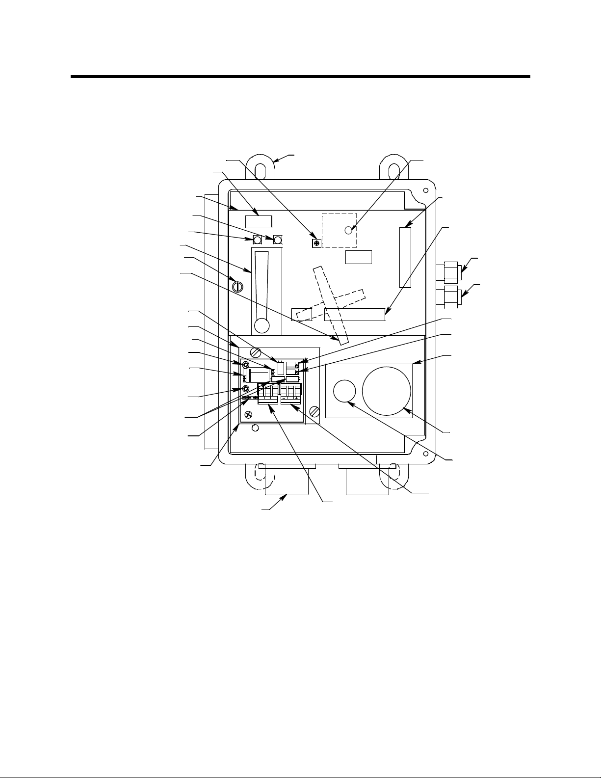
Description
This section describes the components of the sample draw detector. It is a 4 to 20 mA type
detector head. The sample draw detector consists of the housing, flow system, and
detection system.
Flow Adjust Pot
Pum p/Flo w Switch
Terminal Strip
Main Circuit Board
Fail LED
Pilot LED
Flowmeter
Bypass valve
Hydrophobic Filter
(Behind Ma in
Cir cuit B oard )
Load Voltage Po t
Amplifier Plate
Factory Use Jump er Strip
- Test Point, Black
Ga s Sele c tion Ju mp er,
In Hexane Position
+ Test Point, Red
Factory Set Pots
Factory Us e Jumper Str ip
Amplifier
1
2
3
4
Gas Select
1-2 Hex
3-4 H2
DETECTOR
Moun t i ng Foot, 4X
ZER O
SPAN
SWBR
PWR/ SIG
Flow Alarm Setpoint
Adju stment Screw
Detector/Amplifier
Terminal Strip
Interconnect
Terminal Strip
Exhaust
Inlet
Zero Pot
Span Pot
Flow Block
Chamber
Not Used
ppm Hexane
Detector
Controller
Terminal Strip
3/4" Conduit Hu b, 2X
Detector
Terminal Strip
Figure 1: Component Location
Housing
The sample draw detector’s fiberglass housing is weather- and corrosion-resistant. It is
suitable for installation where general purpose equipment is in use.
The housing door is hinged on the left side and is secured by two latches on the right side.
The flowmeter and status LEDs are visible through a window in the housing door.
Four mounting feet are attached to the back of the housing (one at each corner). Use the
mounting feet to install the housing to a vertical surface. Use the two conduit hubs on the
bottom of the housing to make wiring connections.
An aluminum subpanel is mounted to th e interior of the housing. The sample draw
detector’s internal components are mounted to the subpanel.
35-3000RK-10 PPM Hexane Sample Draw Dete ctor • 5
Page 6

Flow System
The sample draw detector’s flow system consists of the inlet fitting, exhaust fitting, pump,
flowmeter, bypass valve, flow block, status LEDs, and pressure switch (see Figure 1).
Figure 2 below illus trates how the gas sample moves through the flow system.
Bypass
Valve
Inlet
Hydrophobic
Filter
Pump
Detector
Figure 2: Flow Diagram
Flowmeter
Presur e Swit ch
Exhaust
Inlet Fitting
The inlet fitting on the right side of the housing allows the gas sample to enter the sampledraw detector. The inlet fitting accepts 1/4 in. rigid tubing. See “Connecting the Sample
Lines to the Sample Draw Detector” on pag e 11 to connect tubing to the inlet fitting.
Exhaust Fitting
The exhaust fitting on the right side of the housing allows the gas sample to exit the
sample draw detector. The exhaust fitting accepts 1/4 in. rigid tubing. See the
“Connecting the Sample Lines to the Sample Draw Detector” on page 11 to connect tubing
to the exhaust fitting.
Hydrophobic Filter
The hydrophobic filter is behind the main circuit board near the bottom edge of the board.
The filter prevents particulates and water in the incoming gas sample from damaging the
flow and detection systems. Replace the filter when it appears dirty, discolored, or
clogged.
Pump
The pump is behind the main circuit board near the top of the sample-draw detector.
The pump pulls the gas sample into the sample-draw detector. The pump operates on
24 VAC, which is generated f rom the 24 VDC supplied to the sample draw detector.
Flowmeter
The flowmeter is attached to the main circuit board near the top left corner (see Figure 1.)
You can see it through the window in the door. A ball in the flowmeter column indicates
the flow rate of the sample draw detector. The flowmeter measures the flow in the range
0.2 to 2.0 SCFH (Standard Cubic Feet per Hour). The optimum flow rate is 1.5 SCFH.
6 • 35-3000RK-10 PPM Hexane Sample Draw Detector
Page 7

Bypass valve
The bypass valve is to the left of the flowmeter. The bypass valve adjusts the flow rate to
the detector. U se a flat-bla de screwdriver to adjust the bypass valve.
NOTE: The bypass valve allows fine adjustments of the f low rate to the detector. To
adjust the total flow and for a wider range of adjustment, use the flow adjust pot
(see Figure 1).
Flow Block
The flow block is an aluminum block with a chamber for the detector and passages that
route the sample to and from the detector. It is located in the lower right corner of the
sample draw detector. The flow block has an unused chamber that is used for an oxygen
detector in other versions of the 35-3000RK.
Status LEDs
T wo status L EDs are above the flowmeter. They are also visible through the window in the
housing door.
Pilot LED
The green Pilot LED is on when the sample-draw detector is receiving power from the
Pioneer.
Fail LED
The red Fail LED is on when the sample flow rate is below the low flow level.
Pressure switch
The pressure switch is mounted to the opposite side of the main circuit board. The
pressure switch monitors the flow rate of the incoming gas sample.
If the flow rate falls below the preset low flow level, the pressure switch causes the fail
relay to interrupt the signal in the 4-20 mA line. This causes a downscale reading at the
monitor. The low flow level is factory set at 0.6 SCFH (±0.2 SC FH). See “Adjusting the
Low Flow Setting” on page 20 to adjust this setting if necessary.
Detection System
The detection system consists of the ppm hexane detector, the amplifier, and the main
circuit board.
PPM Hexane Detector
The ppm hexane detector is a MOS type (metal oxide semiconductor) detector packaged
in a 5 pin plug-in detector housing with a sintered metal flame arrestor on one end
allowing ambient air to diffuse into the detector. The flame arre stor also contains any
sparks which may occur within the detector. The 5 pins allow you to connect the detector
to the detector cable which has a mating 5 pin connector. The three color-coded leads of
the detector cable allow you to connect the detector to the amplifier. The output of the
detector is non-linear and is linearized by th e am plifier (see below).
The detector is installed in an aluminum flow block. The flow block is mounted to the
aluminum subpanel near the bottom right corner of the sample draw detector.
NOTE: The flow block includes a chamber for an oxygen sensor. This version of the
sample draw detector does not include the oxygen sensor.
35-3000RK-10 PPM Hexane Sample Draw Dete ctor • 7
Page 8

Amplifier
The amplifier is mounted to the left of the detector. It is installed on a small plate with
adhesive foam and the plate is mounted to two standoffs. The amplifier converts the nonlinear electrical output from the detector to a linear 4 to 20 mA signal that corresponds to
the detection range and transmits the signal to a gas monitoring controller. The a mplifier
consists of the span pot, zero pot, load voltage pot, gas select jumper strip, controller
terminal strip, detector terminal strip and test points.
Zero Pot
The zero pot is located in the upper right corner of the amplifier (see Figure 1). Use a small
flat blade screwdriver to turn the zero pot’s adjustment screw and adjust the amplifier’s
zero (fresh air) output during the start-up and calibration procedures.
Span Pot
The span pot is located below the zero pot (see Figure 1). Use a small flat blade
screwdriver to turn the span pot’s adjustment screw and adjust the amplifier’s gas
response output du ring the calibration procedure.
Load voltage pot
The load voltage pot is located to the left of the zero and span pots (see Figure 1). The load
voltage pot is not needed for normal scheduled maintenance, so it is a right angle pot that
is not accessible unless the amplifier is lifted out of the sample draw detector enough to
access the adjustment screw. Use a small flat blade screwdriver to turn the load voltage
pot’s adjustment screw and adjust the amplifier’s detector load voltage when the detector
or amplifier is replaced.
CAUTION: The amplifier includes additional pots. They are factory-set. Do not adjust the m.
Gas Select Jumper Strip
The gas select jumper strip is a three position pin style terminal strip located in the upper
left corner of the amplifier. A label next to the jumper strip indicates which pins must be
shorted to select hexane or hydrogen. A jumper block is installed at the factory over pins 1
& 2 to select hexane as the gas type. The gas type defines the linearizing curve used by the
amplifier to linearize the detector output.
Controller and Detector Terminal Strips
The controller terminal strip and detector terminal strip are three position terminal strips.
The controller terminal strip is located on the right side of the amplifier and the detector
terminal strip is to the right of it. Both terminal strips are factory wired to the sensor and
main circuit board.
Test points
The test points are located on the left side of the amplifier. The black - test point is in the
upper left corner and the red + test point is located below it on the other side of the gas
select jumper strip. A 100 mV - 500 mV output is available at these test points for use
during calibration.
8 • 35-3000RK-10 PPM Hexane Sample Draw Detector
Page 9

Main Circuit Board
The main circuit board includes the interconnect terminal strip, detector/amplifier
terminal strip, pump terminal strip, and relay (see Figure 1).
NOTE: The flowmeter and status LEDs are mounted to the main circuit board but are
considered part of the flow system.
Interconnect Terminal Strip
The interconnect terminal strip is the nine point terminal strip near the bottom edge of the
main circuit board. Use the interconnect terminal strip to connect the sample draw
detector to a controller.
Detector/Amplifier Terminal Strip
The detector/amplifier terminal strip is the nine-po int terminal strip near the right edge
of the circuit board. Use the detector/amplifier terminal strip to connect the amplifier to
the main circuit board. In this version of the 35-3000RK the detector is not wired to the
detector/amplifier terminal strip but is wired to the amplifier’s detector terminal strip.
NOTE: The amplifier is factory wired to the sample draw detector’s detecto r /amplifier
terminal strip. See “Wiring the Sample Draw Detector” on page 11 for all wiring
procedures related to the sample draw detector.
Pump terminal strip
The pump terminal strip is the four point terminal strip near the top edge of the circuit
board. Use the pump terminal strip to connect the pump and pressure switch to the main
circuit board.
NOTE: The pump and pressure switch are factory wired to the pump terminal strip. See
“Wiring the Sample Draw Detector” on page 11 for all wiring procedures related
to the sample draw detector.
Relay
The relay is to the left of the detector/amplifier terminal strip. The amplifier output to the
controller is routed through the relay contacts and if the pressure switch senses a low flow
condition, the relay interrupts the output from the amplifier. The interrupted amplifier
output causes a fail condition at the controller.
35-3000RK-10 PPM Hexane Sample Draw Dete ctor • 9
Page 10

Installation
This section describes procedures to mount the sample draw detector in the monitoring
environment and wire the sample draw detector to a controller.
Mounting the Sample Draw Detector
1. Select the mounting site. Consider the following when you select the mounting site.
• Is there enough room to open the housing door and make wiring connections at
the bottom of the housing and tubing connections at the right of the housing?
Make sure there is sufficient room to perform start-up, maintenance, and
calibration procedures.
• Are the flowmeter and status LEDs visible?
7.3 in.
6.5 in.
4.0 in.
9.3
in.
8.5
in.
8.9
in.
3/4 in. conduit hub
(total of 2 hubs)
Note: The housing is 4.25 in. deep.
Figure 3: Outline & Mounting Dimensions
2. Close and lat ch the housing door.
10 • 35-3000RK-10 PPM Hexane Sample Draw Detector
Page 11

NOTE: The sample draw detector is shipped with the mounting feet “tucked under” the
housing to protect the mounting feet during shipment.
3. Slightly loosen the screw that secures one of the mounting feet to the housing, then
rotate the mounting foot 180 degrees (see Figure 3).
4. Tighten the screw that secures the mounting foot to the housing.
5. Repeat steps 3 and 4 for the remaining three mounting feet.
6. Position the sample draw housing on a vertical surface at eye level (4 1/2 to 5 feet
from the floor).
7. Insert 1/4 in. or 5/16 screws through the slots in the mounting feet to secure the
housing to the mounting surface.
Connecting the Sample Lines to the Sample Draw Detector
It is important to use the appropriate tubing material for the 0 - 500 ppm hexane sample
draw detector. To avoid the possibility of losing sample in the inlet tubing, use either
stainless steel, rigid polypropylene, or flexible polyurethane tubing.
1. Attach 1/4 inch O.D. stainless steel, polypropylene, or polyurethane sample tubing to
the inlet fitting.
CAUTION: If you use flexible sample tubing (polyurethane for example), use an appropriate
metal insert to seal t he connection between the tubing and the INLET fitting. See
“Parts List” on page 26 for an example of an appropriate metal insert.
2. Place the opposite end of the tubing in the samplin g area.
CAUTION: Avoid loops or slumps in the incoming sample line. T o reduce response time, keep the
incoming sample line as short as possibl e.
3. Attach rigid sample tubing or flexible tubing with an appropriate insert to the exhaust
fitting.
4. Route the opposite end of the tubing to an open area where the sample can safely
disperse.
Wiring the Sample Draw Detector
WARNING: Always verify that all power is off before making any wiring connections
1. Turn off the controller.
2. Turn off power to the controller.
3. Unlatch and open the housing door o f the sample draw detector.
4. Guide a three-conductor, shielded cable or three wires in conduit through one of the
conduit hubs at the bottom of the sample draw detector housing.
5. Connect the cable or wires in conduit to the sample draw detector’s interconnect
terminal strip as shown in Figure 4.
6. Close and latch the housing door of the sample-draw detector.
35-3000RK-10 PPM Hexane Sample Dra w Detector • 11
Page 12

CAUTION: If using shielded cable, leave t he cab l e’s drain wire disconnected and
insulated at the sample draw detector. You will connect it to an avai la ble
chassis ground at the controller.
7. Route the shielded cable or wires in conduit leading from the sample draw detector to
the controller.
8. Connect the cable’s dr ain wire to an available ch assis ground at the controller. A
ground stud is typically a convenient location to conn ect to chassis ground in an RKI
controller.
Samp le Dra w Housin g
Ga s Sel ect
1
2
1- 2 He x
3
3- 4 H2
4
WB R
DETECTOR
Factory W ired
Pump,
ZERO
SPAN
S
PWR/ SIG
Red
Black
White
Detector Socket
PSWPUMP
Ampli fier, F actor y W ire d
De tec to r in
Sample Cham ber,
Factory W ired
Pressure Switch ,
Factory Wired
Ma in PCB
115 VAC In
St ripNot Used
in This Version
+
24VGNDBLKGRN 4/20
WHTRD
P- AMPAMP
4/ 20 (S )
24 V (+ )
GND (-)
LEL/ O2
GND
115VAC
NH
RD
GRN
Figure 4: Internal and Field Wiring Diagram
12 • 35-3000RK-10 PPM Hexane Sample Draw Detector
Cable S hield
+_4/2024VGNDBLKWHT
P- AMPAM PLEL/O2
Controller
+24 VDC
S (4 - 20mA In)
- (DCGround )
Page 13

Start Up
This section describes procedures to start up the sample draw detector and place the
sample draw detector into normal operation.
Introducing Incoming Power
1. Complete the installation procedures described earlier in this manual.
2. Verify that the wiring to the controller is correct and secure.
3. Turn on or plug in the power to the controller.
4. Turn on the controller.
5. Verify that the Pilot LED is on.
6. Verify that the flowmeter indicates a flow rate of approximately 1.5 SCFH. If
necessary, use the bypass valve or flow adj ust pot to adjust the flow rate.
NOTE: The following step tests for leaks in the sample line. This test may cause a low
flow condition at the sample draw detector and a fail condition at the controller.
7. Verify that the incoming sample line is not leaking. To test the sample line, plug the
open end of the sample line with your thumb. If the flowmeter ball drops to the
bottom of the flowmeter, the incoming sample line is not leaking.
8. Remove your thumb from the sample line, verify the flowmeter returns to a normal
flow rate.
Sample Draw Detector Burn-In Period
Once power has been applied to the sample draw detector, it will take several days for the
signal to the controller to stabilize completely. This is the burn-in period. The zero reading
may be slightly above zero after startup and will stabilize in about 5 to 7 days. The sample
draw detector is calibrated at the factory before shipment, so it is not necessary to calibrate
the sample draw detector after startup. If calibration of the sample draw detector after
startup is desired, wait at least 5 days afte r s tartup before calibrating the sample draw
detector. A burn-in period of 7 days is recommended. See “Calibration” on page 23 for
calibration instructions.
After the burn-in period, set the zero reading if needed as described in “Calibration” on
page 23.
CAUTION: Do not adjust the zero or span pots for at least 5 days after startup. If the fresh air
reading is high enough to cause unwanted alarms during the burn-in period, adjust
the zero pot only enough to bring the reading below the alarm point.
Setting the Zero Reading
CAUTION: If you suspect the presence of the target ga s in the monitoring environment, see
“Calibration” on page 23 for instructions to use the calibration kit and the zero air
calibration cylinder to introduce “fresh air” to the sample draw detector and verify
an accurate zero setting.
35-3000RK-10 PPM Hexane Sample Dra w Detector • 13
Page 14

1. Verify that the sample draw detector is samplin g a fresh air environment
2. Open the housi ng do or.
3. Set a voltmeter to measure in the millivolt (mV) range.
4. Plug the voltmeter leads into the test points on the amplifier. Plug the positive lead
5. Verify a voltmet er reading of 100 mV (± 2 mV).
6. If necessary, use a small flat-blade screwdriver to adjust the zero pot until the
7. Remove the voltmeter leads from the test points.
8. Close the housing door.
Maintenance
This section describes maintenance procedures. It includes preventive maintenance
procedures. This section also includes procedures to troubleshoot the sample draw
detector , replace components of the sample draw detector , adjust the low flow setting, and
set the load voltage.
(environment known to be free of combustible gas).
into the red + test point; plug the negative lead into the black - test point.
voltmeter reading is 100 mV (± 2 mV).
Preventive Maintenance
This section describes a preventive maintenance schedule to ensure optimum sample
draw detector performance. It includes daily, monthly, and quarterly procedures.
Daily
1. Verify that the pilot LED is on .
2. Verify that the flowmeter indicates a flow rate of approximately 1.5 SCFH. If
necessary use the bypass valve or flow adjust pot to adjust the flow rate to 1.5 SCFH.
3. Verify a reading of 0 ppm (4 mA) at the monitoring device or a reading of 100 mV at
the transmitter test points. Investigate significant changes in the reading.
Monthly
This procedure describes a test to verify that the sample draw detector re sponds pr o perl y
to the target gas.
NOTE: To reduce the response time of this test, use a short incoming sample line. If the
sample draw detector’s sample line is long, connect a shorter line for this test.
Make sure you reconnect the sample line after you complete this procedure.
NOTE: Performing a response test on the sample draw detector may cause alarms. Be
sure to put the controller into its calibration program or disable external alarms
before performing this test.
14 • 35-3000RK-10 PPM Hexane Sample Draw Detector
Page 15

NOTE: The following procedure assumes the use of a calibration kit that includes a
calibration gas cyli nder, a dispensing valve with an on/of f knob, a gas bag, and a
humidifier tube to connect the gas bag to the dispensing valve and to the sample
draw detector inlet fitting. A demand flow regulator calibration kit is also
available.
WARNING: The controller is not an active gas monitoring device during the response
test.
Preparing for the response test
1. Verify that the disp lay reading at the controller is 0 ppm.
If the display reading is not 0, set the zero reading as described in “Calibra tion” on
page 23, then continue this procedure.
2. Follow the instructions in the controller’s operator’s manual for entering calibration
mode.
3. Set a voltmeter to measure in the millivolt (mV) range.
4. Open the housing door, then plug the voltmeter leads into the test points on the
amplifier.
Plug the positive lead into the red + test point; plug the negative lead into the black test point.
5. Use the following formula to determine the correct test points output for the test
sample.
Output (mV) = (calibrating sample/fullscale) X 400 + 100
For example, with a test sample of 250 ppm h exan e and a fu llsc al e se ttin g o f 500 ppm
hexane, the correct output is 300 mV.
300 (mV) = (250/500) X 400 +100
6. Ru n one end of the humidifier tube through the tubing clamp provided with the
calibration kit and connect this end to the fitting on the gas collection bag.
WARNING: The humidifier tube used with this cal i br ation kit includes polyurethane
tubing on each end of the humidifier tu be t o fa cilitate making connections
to hose barbs. Do not clamp on the middle braided tube section of the
humidifier tube. Only clamp on the polyurethane tube on ei ther end of the
humidifier tube.
7. Connect the humidifier tube from the gas collection bag to the in let sample line.
Allow the sample-draw pump to draw out any residual ga s in the gas collection bag.
8. Close the tubing clamp.
NOTE: This step will cause a low flow alarm.
9. Disconnect the humidifier tube from the inlet sample line.
10. Screw the dispensing valve onto the test gas cylinder.
35-3000RK-10 PPM Hexane Sample Dra w Detector • 15
Page 16

11. Connect the humidifier tube from the gas collection bag to the dispensing valve, then
open the clamp.
12. Turn the dispensing valve’s on/off knob counterclockwise to open it. The gas
collection bag begins to fill.
13. Turn the dispensing valve’s on/off knob clockwise to close it when the gas collection
bag appears full.
14. Close the tubing clamp, then disconnect the humidifier tube from the dispensing
valve.
15. Remove the dispensing valve from the gas cylinder.
Performing the response test
1. Connect the humidifier tube from the gas collection bag to the in let sample line.
The sample draw detector’s pump begins pulling the test sample from the gas
collection bag when you connect the tubing to the inlet sample line.
2. After one minute, verify that the test points output stabilizes within ± 20% of the mV
reading you determined earlier for the test sample. If the mV reading is not within ±
20% of the test sample, calibrate the sample draw detector as described in
“Calibration” on page 23.
3. Remove the humidifier tube from the inlet sample line.
4. Remove the voltmeter leads from the amplifier test points.
5. Close the housing door.
6. Unscrew the dispensing valve from the gas cylinder.
7. Return the controller to normal operation.
8. Store the components of the calibration kit in a save place
Biannually
Calibrate the sample draw detector as described in the “Calibration” on page 23.
Troubleshooting
The troubleshooting guide describes symptoms, probable causes, and recommended
action for problems you may encounter with the sample draw combustible gas detector.
NOTE: This troubleshooting guide describes sample draw detector problems only. See
the controller operator’s manual if it exhibits any problems.
Fail condition
Symptoms
• The sample draw detector’s Fail LED is on.
• The controller is operating properly but indicates a reading well below zero.
Probable causes
• The sample draw detector’s flow rate is too low because of an obstructed sample line,
clogged filter, failed pump, etc.
• The sample draw detector is malfunctioning.
• The detector or amplifier wiring is disconnected or misconnected.
16 • 35-3000RK-10 PPM Hexane Sample Draw Detector
Page 17

Recommended action
1. Set the correct flow rate with the bypass valve or flow adjust pot.
2. If you cannot set the correct flow rate, check the sample lines for obstructions or kinks.
3. Inspect the hydrophobic filter to see if it is dirty or clogged with particulate matter or
liquid.
4. Verify that the detector and amplifier wiring are correct and secure. “Installation” on
page 10 describes sample draw detector wiring connections.
5. Calibrate the sample draw detector as described in “Calibration” on page 23.
6. If the fail condition continues, replace the detector as described later in this section.
7. If the fail condition continues, contact RKI Instruments, Inc. for further instruction.
Slow or no response/difficult or unable to calibrate
Symptoms
• The detector responds slowly or doe s not respond during the monthly response test.
• Unable to accurately set the zero or response reading during the calibration
procedure.
• The detector requires frequent calibration.
NOTE: Under “normal” circumstances, the detector requires calibration twice a year.
Some applications may require a more frequent calibration schedule. See
“Calibration Frequency” on page 23 for a discussion of the calibr ation
requirements.
Probable causes
• The calibration cylinder is low, out-dated, or defective.
• The sample draw detector’s flow rate is too low because of an obstructed sample line,
failed pump, etc.
• The sample draw detector is malfunctioning.
Recommended action
1. Ver if y that the cal i brat i on cylin der con t ains an adequate supply of a fresh test sample.
2. If a demand flow regulator calibration kit i s used , use a different demand flow
regulator to determine if the original one if functioning properly.
3. If necessary, set the correct flow rate with the bypass valve or flow adjust po t.
4. If you cannot set the correct flow rate, check the sample line for obstructions or kinks.
5. If the calibration/response difficulties continue, replace the sensor as described later
in this section.
6. If the calibration/response difficulties continue, contact RKI Instruments, Inc., for
further instruction.
Replacing Components of the Sample Draw Detector
This section includes procedures to r eplace the detector, amplifier, hydrophobic filter, and
ferrules.
Replacing the Detector
1. Turn off the controller
35-3000RK-10 PPM Hexane Sample Dra w Detector • 17
Page 18

2. Turn off power to the controller.
3. Open the sample draw detector’s housing door.
4. Unscrew and remove the two screws that secure the sensor retraining plate, then lift
the plate, connector, and detector out of the housing.
5. Unplug the connector from the detector.
6. Verify that you are using the correct replacement sensor (SG-8521 is printed on the
sensor), then plug the sensor into the conn ector.
7. Place the detector in the detector chamber, then position the retaining plate on the two
standoffs.
8. Secure the retaining plate to the standoffs with the two screws you removed in Step 4.
9. Close and lat ch the housing door.
10. Turn on power to the controller.
11. Turn on the controller and place it into normal operation.
12. Allow the sample draw detector to run for 3 hours.
13. Make a preliminary setting of the detector load voltage. See “Setting the Detector
Load Voltage” on page 21. This will be a temporary load voltage setting since the load
voltage will need to be set again after the burn-in period as described below.
14. Perform a preliminary calibration. See “Calibratio n” on page 23. This will be a
temporary calibration since the new detector must burn-in before it can be properly
calibrated.
15. Allow the replacement detector to burn-in for at least 5 days before you continue with
the next step. A burn-in period of 7 days is recommended.
16. After the burn-in period, set the load voltage as described in “Setting the Detector
Load Voltage” on page 21.
17. After setting the load voltage, calibrate the as described in “Calibration” on page 23.
Replacing the Amplifier
If you are replacing the amplifier, it is likely that the sample draw detector has been off
power for an extended period. Make sure to follow the preliminary load voltage and
preliminary calibration recommendations and the burn-in period recommendation befor e
making the final load voltage setting and calibration. The replacement amplifier is
supplied already installed to a small mounting plate like the amplifier that is being
replaced. All references to the amplifier below refer to an amplifier already installed on
the amplifier mounting plate.
1. Turn off the controller.
2. Turn off power to the controller.
3. Open the housi ng do or
4. Unplug the detector terminal strip and controller terminal strip from their sockets on
the amplifier. You may leave the wires connected to the terminal strips.
5. Unscrew and remove the two screws, flat wash e rs , and split lock washers that secure
the old amplifier on its mounting plate to the mounting standoffs.
6. Remove the old amplifier with its mounting plate.
7. Install the detector and controller terminals strips into their sockets on the new
amplifier. See Figure 1 on page 5 or Figure 5 on page 22 for th e location of these
terminal strips If controller leads or detector leads were removed during this
procedure, refer to Figure 4 on page 12 for wiring connections.
18 • 35-3000RK-10 PPM Hexane Sample Draw Detector
Page 19

8. Lay the new amplifier (already installed on its mounting plate) on the mounting
standoffs and install the retaining screws with the flat washers and split lock washers
but do not tighten them down because you will need to pull out the amplifier for
access to the load voltage adjust pot below.
NOTE: When a sample draw detector is first powered up with a new amplifier, the initial
output may be either high or below zero. Be sure to make arrangements so that
this does not cause unwanted alarms.
9. Turn on power to the controller.
10. Turn on the controller and place it into normal operation.
11. Allow the sample draw detector to run for 3 hours.
12. Remove mounting screws, flat washers, and lock washers that retain the amplifier
plate to pull out the amplifier enough to gain access to the load voltage pot and make
a preliminary setting of the detector load voltage. See “Setting the Detector Load
Voltage” on page 21. This will be a te mporary load voltage setting since the load
voltage will need to be set again after the burn-in period as described below.
13. Install the amplifier with its m ounting plate using the retaining screws, flat washers,
and lock washers.
14. Perform a preliminary calibration. See “Calibratio n” on page 23. This will be a
temporary calibration since the detector must burn-in before it can be properly
calibrated.
15. Allow the sample draw detector to burn-in for at least 5 days before you continue
with the next step. A burn-in period of 7 days is recommended.
16. After the burn-in period, set the load voltage as described in “Setting the Detector
Load Voltage” on page 21.
17. After setting the load voltage, calibrate the transmitter as described in “Calibration”
on page 23 of this manual.
Replacing the Hydrophobic Filter
1. Turn off the controller
2. Turn off power to the controller.
3. Open the housing do or of the sample draw detector.
4. Not e which side of the replacement filter’s body has the “INLET” marking. The barb
on this side must be connected to the line coming from the inlet fitting when it is
installed.
5. If necessary, remove the mounting screws flat washers, and lo ck washers that secure
the main circuit board and list the board enough to gain access to the hydrophobic
filter.
6. Disconnect the old filter from the rubber elbows on each end of the filter , then remove
the filter from the sample-draw detector.
7. Con nect the rubber elbow on the tube from the inlet fitting to the side of the
replacement filter with the “INLET” marking, then connect the other rubber elbow to
the other side of the filter.
8. Lay the replacement filter below the main PCB like the old one.
9. If necessary, reinstall the main circuit board.
35-3000RK-10 PPM Hexane Sample Dra w Detector • 19
Page 20

10. Place the controller and sample draw detector into operation
11. Verify that the flow rate is approximately 1.5 SCFH. If necessary, adjust the flow rate
with the bypass valve and/or the flow adjust pot.
12. Close the sample draw detector’s housing door.
Replacing the Ferrules
The inlet and exhaust fittings each includes two ferrules that seal the incoming or exhaust
tubing to the fitting. Replace the ferrules if the seal is bad or if you replace the sample
tubing. Always replace the ferrules as a set.
1. Unscrew the nut that holds the tubing to the fitting from the fitting.
2. Slide the nut away from the end of the tubing.
3. Cut off the end of the sample tube with the old ferrules off about one inch from the
end
4. Slide the nut off the sample tubing.
5. Position the nut so the threaded end is facing you, then insert the bottom (smaller)
ferrule into the nut. Insert the ferrule so the flat side is facing down.
NOTE: Make sure the bottom ferrule is laying flat in the nut.
6. Insert the cone-shaped front ferrule on top of the bottom ferrule. Insert the ferrule so
the smaller end of the cone is facing up.
7. Screw the nut onto the fitting by hand just until it stops turn ing.
8. Insert the sample tubing into the fitting until it bottoms out.
9. Firmly tighten the nut so the ferrules crimp onto the sample tubing and make a seal.
Adjusting the Low Flow Setting
NOTE: Adjusting the low flow setting will cause a low flow alarm at the sample draw
detector and a fail alarm at the controller. Be sure to put the controller into its
calibration program or disable external alarms before making this adjustment
The factory-set low flow setting is 0.6 SCFH (±0.2 SCFH). To adjust the low flow setting:
1. Use the flow adjust pot (VR1) to set the flow to 0.6 SCFH.
If the sample draw detector goes into low flow alarm before you can adjust the flow
down to 0.6 SCFH, adjust the low flow adjustment screw 1/4 turn clockwise, then
attempt to set the flow again. Repeat this step until you are able to adjust the flow to
0.6 SCFH.
The low flow adjustment screw is accessible through a circular cutout in the main
circuit board. See “Component Location” on page 5.
2. Slowly turn the low flow adjustment screw in very small increments counterclockwise
just until the sample draw detect or goes into low flow alarm.
3. Increase the flow using VR1 until the unit is out of low flow alarm.
4. Decrease the flow very slowly and verify that the low flow alarm is 0.6 SCFH (±0.2).
If the low flow alarm is set too lo w, turn the low flow adjustment screw slightly
clockwise. Repeat Step 3 and Step 4 if necessary.
20 • 35-3000RK-10 PPM Hexane Sample Draw Detector
Page 21

5. Use the flow adjust pot (VR1) to set the flow to 1.5 SCFH.
6. Mak e sure the sample draw detector’s Fail LED is off.
Setting the Detector Load Voltage
The detector load voltage must be set when the detector or amplifier is replaced or if you
suspect that it has been changed from the factory setting for your detection range. This
procedure involves setting a voltage while applying calibration gas to the sample draw
detector that matches the full-scale concentration for the sample draw detector. After
replacing the detector or amplifier as described earlier in this manual, the following
procedure must be completed before calibrating the sample draw detector. Be sure to
follow the timing recommendations in “Replacing the Detector” on page 17 and
“Replacing the Amplifier” on page 18 for setting the load voltage.
NOTE: Setting the load voltage may cause alarms. Be sure to put the controller into
calibration mode or disable external alarms before performing this test.
WARNING: The controller is not an active gas monitoring device duri ng the load
voltage setting procedure
NOTE: The following procedure assumes the use of a calibration kit that includes a
calibration gas cylinder equal to the transmitter’s full scale gas concentra tion, a
dispensing valve with an on/off knob, a gas bag, and a humidifier tube to
connect the gas bag to the regulator and to the sample draw detector inlet line.
NOTE: For best accuracy, RKI Instruments, Inc. recommends introducing the gas at the
end of the inlet sample line when makin g a load voltage adjustment instead of
using a temporary short sample line.
1. Put the controller into calibration mode or disable externa l alarms.
2. Open the sample draw detector housing door.
3. Set a voltmeter to measure in the DC millivolt range.
4. Remove th e screw, flat washer, and lock washer retaining the amplifier plate to each
of the two mounting standoffs, then carefully lift the amplifier plate to gain access to
the amplifier’s load voltage adjustm e nt pot. See Figure 5 below for the pot location.
5. Screw the dispensing valve onto the calibration gas cylinder. It must have a gas
concentration equal to the sample draw detector’s full scale.
6. Ru n one end of the humidifier tube through the tubing clamp provided with the
calibration kit and connect this end to the fitting on the gas collection bag.
WARNING: The humidifier tube used with this cal i br ation kit includes polyurethane
tubing on each end of the humidifier tu be t o fa cilitate making connections
to hose barbs. Do not clamp on the middle braided tube section of the
humidifier tube. Only clamp on the polyurethane tube on ei ther end of the
braided humidifier tube.
35-3000RK-10 PPM Hexane Sample Dra w Detector • 21
Page 22

7. Connect the humidifier tube from the gas collection bag to the inlet line.
Allow the sample draw pump to draw out any residual gas in the gas collection bag.
8. Close the tubing clamp.
NOTE: This step will cause a low flow alarm.
9. Disconnect the humidifier tube from the inlet line.
10. Connect the humidifier tube from the gas collection bag to the dispensing valve, then
open the clamp.
11. Turn the d ispensing valve’s on/off knob counterclockwise to open it. The gas
collection bag begins to fill.
12. Turn the dispensing valve’s on/off knob clockwise to close it when the gas collection
bag appears full.
13. Close the clamp, then disconnect the humidifier tube from the regulator.
14. Open the clamp, then connect the humidifier tube from the gas collection bag to the
sample draw detector’s inlet line.
15. Allow the sample draw detector to draw sample for one minute.
16. Measure the voltage between the B terminal on the detector terminal strip and the (negative) terminal on the controller terminal strip as shown belo w in Figure 5.
Load Voltage Pot
Detector Terminal Strip
17. Adjust the load voltage adjust pot until the load volta g e is 4.0 V ± 0.1 V.
18. Allow the sample draw detecto r to draw out any residual gas in the gas collection
bag.
19. Disconnect the humidifier tube from the sample draw detector’s inlet line.
Select1
Gas
2
1-2 Hex
3
3-4 H2
4
WBR
DETECTOR
ZERO
SPAN
S
PWR / SIG
+
Measure Load Voltage
Digital
Between B and -
Vol tmeter
Figure 5: Load Voltage Measurement
Controller Terminal Strip
NOTE: Detector and Controller
Wires Not Shown
20. If necessary , r emove the short inlet line used for this adjustment and re-install the inlet
line.
21. Unscrew the dispensing valve from the calibration cylinder.
22 • 35-3000RK-10 PPM Hexane Sample Draw Detector
Page 23

22. Wait 1 to 2 minutes to allow the combustible gas reading to decrease and stabilize.
23. Re-install the amplifier using the screws, flat w as hers, a nd lock washers removed in
Step 4 above.
24. Calibrate the sample draw detector as described in “Calibration” on page 23
25. Verify that the co ntroller display reading decreases and stabilizes at 0 ppm.
26. Store the components of the calibration kit in a safe and conv enient place.
Calibration Frequency
Although there is no particular calibration frequency that is correct for all sample draw
detector applications, a calibration frequency of every 6 to 12 months is ade quate fo r most
applications. Unless experience in a particular application dictates otherwise, RKI
Instruments, Inc. recommends a calibration frequency of every 6 months.
If an application is not very demanding, for example detection in a clean, temperature
controlled environment where hexane or other combustible gasses are not normally
present and calibration adjustments are minimal at calibration, the n a calibration
frequency of every 12 months is adequate.
If an application is very demanding, for example if hexane or other combustible gasses are
present often and in significant concentrations or the environment is not well controlled,
then more frequent calibration than every 6 months may be necessary.
Calibration
This section describes how to calibrate the sample draw detector . It includes pr ocedures to
assemble the calibration kit, set the zero reading, set the response reading, and return to
normal operation.
NOTE: The following procedure assumes the use of a calibration kit that includes a
calibration gas cyli nder, a dispensing valve with an on/of f knob, a gas bag, and a
humidifier tube to connect the gas bag to the dispensing valve and to the sample
draw detector inlet line. A demand flow regulator calibration kit is also available.
Calibration Kit Humidifier Tube
The sample draw detector requires normal atmospheric humidi ty levels to respond
properly to hexane because of the low ppm levels involved. Normal atmospheric
humidity variations do not affect the detecto r’s response to hexane in ambient air, but the
ultra low humidity level of gas from a calibration cylin der requires that the calibration
sample be humidified for the detector to respond properly. The calibration kit for the
sample draw detector includes a humidifier tube with flexible polyurethane on each end
that is not normally included in other calibration kits. This humidifier tube humidifies the
calibration sample flowing through it by absorbing humidity from the ambient air and
adding it to the sample. The humidifier tube is included in Table 2 on page 26.
WARNING: A humidifier tube must be used when calibrating the sample draw detector
for the detector to respond properly to the calibration gas. Failure to use a
humidifier tube will result in an inaccurate calibration.
35-3000RK-10 PPM Hexane Sample Dra w Detector • 23
Page 24

Prepari ng for Ca libration
NOTE: Calibrating the sample draw detector may cause alarms. Be sure to put the
controller into calibration mode or disable external alarms before continui ng.
1. Put the controller into calibration mode or disable external alarms.
2. Open the sample draw detector’s housing door.
3. Set a voltmeter to measure in the DC millivolt (mV) range.
4. Plug the positive lead into the red + test point; plug the negative lead into the black test point.
5. Use the following formula to determine the correct test points output for the
calibrating sample.
Output (mV) = (calibrating sample/fullscale) X 400 + 100
For example, with a calibrating sample of 250 ppm hexane and a fullscale setting of
500 ppm hexane, the correct output is 300 mV.
300 (mV) = (250/500) X 400 +100
Assembling the Calibration Kit
NOTE: If you can verify a fresh air environment, it is not necessary to use a zero air
calibrating sample to set the zero reading. Screw the dispensing valve onto the
hexane calibration cylinder and go to the next section, “Setting the Zero
Reading.”
1. Screw the dispensing valve onto the zero air calibration cylinder.
2. Ru n one end of the humidifier tube through the tubing clamp provided with the
calibration kit and connect this end to the fitting on the gas collection bag.
WARNING: The humidifier tube used with this cal i br ation kit includes polyurethane
tubing on each end of the humidifier tu be t o fa cilitate making connections
to hose barbs. Do not clamp on the middle braided tube section of the
humidifier tube. Only clamp on the polyurethane tube on ei ther end of the
braided humidifier tube.
NOTE: For best accuracy, RKI Instruments, Inc. recommends calibrating the sample
draw detector by introducing the calibration gas at the end of the inlet sample
line and not using a shorter temporary inlet line.
3. Connect the humidifier tube from the gas collection bag to the in let sample line.
Allow the sample draw pump to draw out any residual gas in the gas collection bag.
4. Close the tubing clamp.
NOTE: This step will cause a low flow alarm.
5. Disconnect the humidifier tube from the inlet sample line.
24 • 35-3000RK-10 PPM Hexane Sample Draw Detector
Page 25

6. Connect the humidifier tube from the gas collection bag to the dispensing valve, then
open the clamp.
7. Turn the dispensing valve’s on/off knob counterclockwise to open the dispensing
valve. The gas collection bag begins to fill.
8. Turn the dispensing valve’s on/off knob clockwise to close the dispensing valve when
the gas collection bag appears full.
9. Close the tubing clamp, then disconnect the humidifier tube from the dispensing
valve.
Setting the Zero Reading
1. Open the tubi ng clamp, then connect the humidifier tube from the gas collection bag
to the sample draw detector’s inlet sample lin e. This step is not necessary if you
verified a fresh air environment earlier in this procedure.
2. Allow the sample draw detector to sample the gas for one minute. If the inlet line is
long, allow time for the sample to reach the detector, about 1 second per foot of
sample lin e .
3. Verify a voltmet er reading of 100 mV (± 2 mV).
4. If necessary, use a small flat-blade screwdriver to adjust the zero pot until the
voltmeter reading is 100 mV (± 2 mV).
5. Allow the sample draw detector to d r aw out any residual gas in the gas collection
bag, then close the clamp. Step 5 through Step 7 are not necessary if you verified a
fresh air environment earlier in this procedure. If you verified a fresh air
environment, go to step Step 1 in the next section, Setting the Response Reading.
NOTE: This step will cause a low flow alarm.
6. Disconnect the humidifier tube from the inlet sample line.
7. Unscrew the dispensing valve from the zero air calibration cylinder, then screw the
dispensing valve onto the hexane calibration cylinder.
Setting the Response Reading
1. Con nect th e humidifier tube from the gas collection bag to the dispensing valve
(installed on the hexane calibration cylind e r), then open the tubing clamp.
2. Turn the dispensing valve’s on/off knob counterclockwise to open the dispensing
valve. The gas collection bag begins to fill.
3. Turn the dispensing valve’s on/off knob clockwise to close the dispensing valve when
the gas collection bag appears full.
4. Close the tubing clamp, then disconnect the humidifier tube from the dispensing
valve.
5. Open the tubi ng clamp, then connect the humidifier tube from the gas collection bag
to the sample draw detector’s inlet sample lin e.
6. Allow the sample draw detector to draw calibration gas for one minute. If the sample
line is long, allow time for the sample to reach the detector, about 1 minute per foot of
sample lin e .
7. Verify that the test points o utput matches the response output (±2 mV) you
determined earlier.
35-3000RK-10 PPM Hexane Sample Dra w Detector • 25
Page 26

Parts List
8. If necessary, use the span pot on the ampl ifier to a djust the reading to match the
correct mV output.
9. Allow the sample draw detector to d r aw out any residual gas in the gas collection
bag.
10. Disconnect the sample tubing from the sample-draw de tector’s inlet sample line.
11. Remove the test jacks from the test points.
12. Close the housing door.
13. Unscrew the dispensing valve from the calibration cylinder.
14. Wait 1 to 2 minutes to allow the combustible gas reading to decrease.
15. Store the components of the calibration kit in a safe and conv enient place.
Table 2 lists replacement parts and accessories for the sample draw detector.
Table 2: Parts List
Part Number Description
17-2593RK Brass insert (for INLET and EXHAUST fi ttings)
17-2683RK Front ferrule (for INLET and EXHAUST fittings)
17-2688RK Back ferrule (for INLET and EXHAUST fittings)
30-0610RK Pump
33-0163RK Filter (Boston DFU9933-05-DQ)
33-2001RK-01 6 inch humidifier tube for fixed system ca libration kit
71-0151RK 35-3000RKA-10 Operator’s Manual (this document)
81-0023RK-21 Calibration cylinder (500 ppm hexane in air, 34 liter)
81-0083RK-23 Calibration cylinder (500 ppm hexane in air, 103 liter)
81-0076RK-01 Zero air calibration cylinder (34 liter)
81-0076RK-03 Zero air calibration cylinder (103 liter)
81-1001RK D ispensing valve (with knob)
81-1054RK Demand flow regulator
81-1126RK Gas collection bag (2 liter)
SG-8521 MOS combustible detector for hexane
26 • 35-3000RK-10 PPM Hexane Sample Draw Detector
 Loading...