

Page 1

30-0951RK-H2S Sample Draw
Aspirator Adapter
Operator’s Manual
Part Number: 71-0125RK
Revision: A
Released: 6/2/10
www.rkiinstruments.com
Page 2

Product Warranty
RKI Instruments, Inc. warrants gas alarm equipment sold by us to be free from defects in
materials, workmanship, and performance for a period of one year from the date of
shipment from RKI Instruments, Inc. Any parts found defective within that period will be
repaired or replaced, at our option, free of charge. Parts must be returned to RKI
Instruments, Inc. for repair or replacement. This warranty does not apply to those items
which by their nature are subject to deterioration or consumption in normal ser v ice, and
which must be cleaned, repaired or replaced on a routine basis. Examples of such items
are:
a) Pump diaphragms and valves c) Batteries
b) Fuses d) Filter elements
W arranty is voided by abuse including mechanical damage, alteration, rough handling, or
repair procedures not in accordance with instruction manual. This warranty indicates the
full extend of our liability, and we are not responsible for removal or replacement costs,
local repair costs, transportation costs, or contingent expenses incurred without our prior
approval.
THIS WARRANTY IS EXPRESSLY IN LIEU OF ANY AND ALL OTHER
WARRANTIES AND REPRESENTATIONS, EXPRESSED OR IMPLIED, AND
ALL OTHER OBLIGATIONS OR LIABILITIES ON THE PART OF RKI
INSTRUMENTS, INC. INCLUDING BUT NOT LIMITED TO, THE WARRANTY OF
MERCHANTABILITY OR FITNESS FOR A PARTICULAR PURPOSE. IN NO
EVENT SHALL RKI INSTRUMENTS, INC. BE LIABLE FOR INDIRECT,
INCIDENTAL OR CONSEQUENTIAL LOSS OR DAMAGE OF ANY KIND
CONNECTED WITH THE USE OF ITS PRODUCTS OR FAILURE OF ITS
PRODUCTS TO FUNCTION OR OPERATE PROPERLY.
This warranty cover s i nstruments and part s sold to users only by authorized distributors,
dealers and representatives as appointed by RKI Instruments, Inc.
We do no t as su me indemnif ic a t ion for any accident or d amage caused b y t he op e r a t ion of
this gas monitor and our warranty is lim ited to the replacement of parts or our complete
goods. W arranty covers parts and labor performed at RKI Instruments, Inc. only, and does
not cover field labor or shipment of parts back to RKI Instruments, Inc.
2 • 30-0951RK-H2S Samp le Draw Aspirator Adapter
Page 3

Overview
This manual describes the 30-0951RK-H2S sample draw aspirator adapter. It also
describes how to install and use the adapter. A spare parts list at the end of this manual
lists replacement parts.
Specifications
Table 1 lists specifications for the Sample Draw Aspirator Adapter.
Table 1: Specifications
Applicable Detec t ors • 65-2423RK-0 5, H
• Consult RKI Instruments, Inc. for othe r detectors
Maximum Inlet Pressure 300 psi
Outlet Pressure to Aspirator 5 - 50 psi adjustable (determined by required flow rate)
Recommended Flow Rate 3 SCFH (standard cubic feet per hour)
S detector
2
30-0951RK-H2S Sample Draw Aspirato r Adapter • 3
Page 4
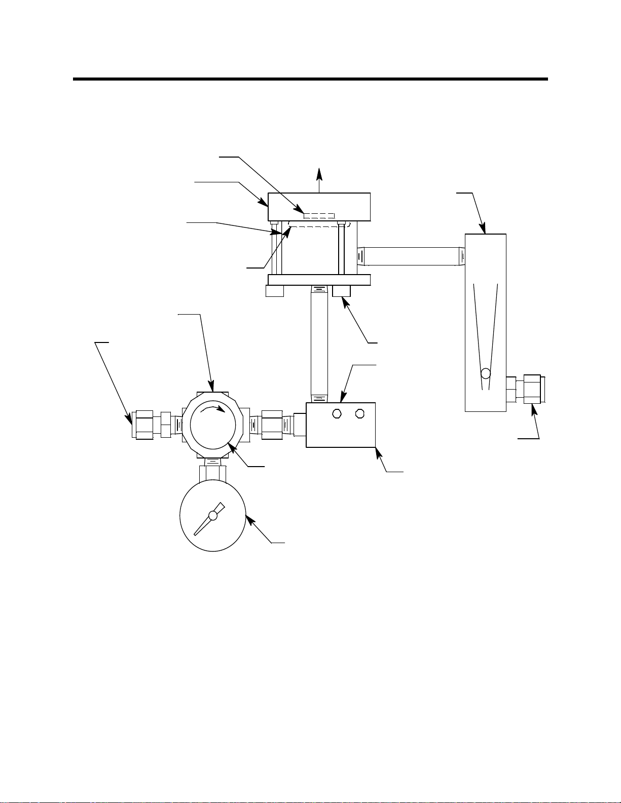
Description
Adapter Gasket (in
bottom of ad apter)
Sensor Adapter
Sensor Chamber
Pressure Regul ator
The sample draw aspirator adapter uses compressed air flowing through a venturi to
draw air into a sa mple chamber. The sample draw adapter screws directly onto the gas
detector.
Screw Onto Combustible
Sensor
Flowmeter
Chamber O-ring (in top of
chamber)
1/4 O.D. Tube
Compr essed Ai r
Inle t Fitting
The sample draw adapter consists of four major components (see Figure 1): the regulator,
aspirator, detector adapter, detector chamber, and flowmeter.
Regulator
Thumbscrew(3X)
As pi r ator
+
-
Pressure Adj ustment
Knob
Pressue Gauge
1/4 O.D. Tube Sample
Aspirator/Sa mple
Exhaust
(1/8 NPT female)
Inle t Fitting
Figure 1: Component Location
The regulator has an inlet port on its left side with a 1/4” tube fitting. The maximum
allowable inlet pressure is 300 psi. A gauge at the bottom of the regulator indicates the
output pressure. The output pressure, and detector flow, can be adjusted using the knob
on the front of the regulator. The detector flow rise s or fal ls a s the o utput pressure is
increased or decreased.
4 • 30-0951RK-H2S Samp le Draw Aspirator Adapter
Page 5

Aspirator
The aspirator inlet is connected to the output port on the right side of the regulator and
the vacuum port on top is connected to the detector chamber. It has a venturi tube inside
it which generates a vacuum at its top port when compressed air flows through it. The
compressed air and the air drawn from the detector chamber into the top port of the
aspirator both exhaust at the right side of the aspirator.
Detector Adapter
The detector adapter screws directly onto the H2S detector. It is inst alle d han d ti ght . I t ha s
an o-ring inside it which seals against the detector. When removing this adapter to change
the detector, be sure not to lose this o-ring.
Detector Chamber
The chamber has three thumbscrews which fasten it to the detector adapter. An o-ring at
the top of the chamber seals the chamber/adapter interface. The inlet of the chamber is on
the right side and is connected to the exhaust of the flowmeter. The exhaust of the
chamber is at the bottom and is connected to the vacuum port of the aspirator.
Flowmeter
The flowmeter indicates the flow to the detector. It has a 1/4” tube fitting at its inlet port
and its exhaust port is connected to the detector chamber. The flowmeter’s indication
range is 1 - 10 SCF H. I t has no flow adj ustm ent v alv e bec ause the fl owra te is con tr o lle d by
the regulator.
Installation
8.20 max
9.50 max
Scre wOntoCombustibleSensor
+
-
1/4O.D.TubeCom pressedAir Inlet
Fitting
1/4 O.D.Tube Sample
Inlet Fitting
Aspirator/Sampl e
Exhaust
(1/8 NPTfemale)
4.00 max
1.25
Figure 2: Outline & Mounting Dimensions
30-0951RK-H2S Sample Draw Aspirato r Adapter • 5
Page 6

1. Install and startup the detector head as described in the detector head operator’s
manual. Make sure there is sufficient room between the detector and the mounting
surface to install the sample draw adapter.
2. The sample draw adapter is no rmally shipped installed to the detector. If not, screw
the detector adapter onto the detector tightening firmly by hand and then attach the
chamber (with the regulator, aspirator and flowmeter attached) onto the detector
adapter with the three captive thumbscrews.
CAUTION: Make sure the detector adapter is installed tightly and after installation is complete
verify that the detector adapter is still tightened firmly onto the d etect or t o avoid
possible leaks.
3. Connect a sample line from the area to be sampled to the inlet fitting on the
flowmeter. The fitting accepts 1/4” OD rigid metal tubing. Stainless steel tubing is
recommended for the inlet line on the H
4. The aspirator exhaust includes the sample air. It m ay be routed to a different area
where it can be exhausted safely by installing a tube fitting in the exhaust port of the
aspirator and running tubing to the “safe” area from this port. The port has 1/8 NPT
female threads.
5. T urn the r egulator adjustment knob completely counterclockwise and then turn it one
turn clockwise so that the flow will start out at a low level when the compressed air is
connected and turned on.
S sample draw adapter
2
Calibration
6. Connect a compressed air source up to a maximum of 300 psi to the inlet of the
regulator . The r egulator is only rated up to 300 PSI inlet pressure. Adjust the regulator
adjustment knob so that the f lowmeter indicates 3 SCFH. The regulator exhaust
pressure indicated by the regulator gauge will vary for a particular flow depending
on the length of the sample line and other restrictions such as filters. Typically the
pressure will be between 5 and 10 psi for short sample runs. It will be higher for
longer sample runs and if filters are used.
7. Calibrate the detector head as described below.
NOTE: Calibrate the detector head with the sample draw adapter installed to insure an
accurate reading.
1. Follow the instructions in the detector head operato r’s manual for setting the zero
reading and making span adjustments.
2. When introducing gas to the detector, fill a gas sample bag with a regulator or
dispensing valve. See “Parts List” on page 7 for available parts.
NOTE: A gas bag is recommended for calibration instead of a demand flow regulator because a
demand flow regulator introduces enough flow restriction to significantly reduce the
flow. If a demand flow regulator is used, the flow will have to be adjusted up to 3 SCFH
while the regulator is connected during calibration and down to 3 SCFH after calibration.
3. Connect the sample bag tubing to the inlet of the flowmete r.
4. Allow the sample draw adapter to draw sample for 2 minutes and then make any
6 • 30-0951RK-H2S Samp le Draw Aspirator Adapter
Page 7

Parts List
calibration adjustments necessary.
5. Disconnect the sample bag from the flowmet e r inlet.
Table 2 lists replacement parts and accessories for the sample draw adapter.
Table 2: Parts List
Part Number Description
06-1248RK Tubing, 3/16 x 5/16, polyuret hane, for calibration kit
07-7218RK O-ring, 0.987 ID x .103, buna, for detector adapter
07-7225RK O-ring, 1.243 ID x .139, buna, for detector chamber
13-1070RK Captive panel screw, 10-32 x 1.75
81-0151RK-02 Gas cylinder, 25 PPM H
81-0151RK-04 Gas cylinder, 25 PPM H
S in nitrogen, 58 liter, aluminum
2
S in nitrogen, 34 liter, aluminum
2
81-1051RK-60 Regulator with gauge and knob, 6 LPM, for 34 liter and 58 liter
aluminum cylinders
81-1127RK Gas bag with fittings and hosebarb, 12 inches x 12 inches, 5 liters,
tedlar
30-0951RK-H2S Sample Draw Aspirato r Adapter • 7
 Loading...