

Page 1

12 VDC Beacon 200
Operator’s Manual
Part Number: 71-0293RK
Revision: P1
Released: 10/4/13
www.rkiinstruments.com
Page 2

Product Warranty
RKI Instruments, Inc. warrants gas alarm equipment sold by us to be free
from defects in materials, workmanship, and performance for a period of
one year from date of sh ipm ent from RKI Instr uments, Inc. Any part s fo und
defective within that period will be repaired or replaced, at our option, free
of charge. This warranty does not apply to those items, which by their
nature, are subject to deterioration or consumption in normal service, and
which must be clean ed, rep aired, or replace d on a rout ine basis. Exa mples
of such items are as follows:
a) Absorbent cartridges d) Batteries
b) Pump diaphragms and valves e) Filter elements
c) Fuses
Warranty is voided by abuse including mechanical damage, alteration,
rough handling, or repair procedures not in accordance with the operator’s
manual. This warranty indicates the full extent of our liability, and we are
not responsible for removal or replacement costs, local repair costs,
transportation costs, or contingent expenses incurred without our prior
approval.
THIS WARRANTY IS EXPRESSLY IN LIEU OF ANY AND ALL OTHER
WARRANTIES AND REPRESENTATIONS, EXPRESSED OR IMPLIED,
AND ALL OTHER OBLIGATIONS OR LIABILITIES ON THE PART OF
RKI INSTRUMENTS, INC. INCLUDING BUT NOT LIMITED TO, THE
WARRANTY OF MERCHANTABILITY OR FITNESS FOR A
PARTICULAR PURPOSE. IN NO EVENT SHALL RKI INSTRUMENTS,
INC. BE LIABLE FOR INDIRECT, INCIDENTAL, OR CONSEQUENTIAL
LOSS OR DAMAGE OF ANY KIND CONNECTED WITH THE USE OF
ITS PRODUCTS OR FAILURE OF ITS PRODUCTS TO FUNCTION OR
OPERATE PROPERLY.
This warranty covers instruments and parts sold to users by authorized
distributors, de alers, and r epresenta tives as appo inted by R KI Instrument s,
Inc.
We do not assume indemn ification for any accident or damage caused by
the operation of this gas monitor, and our warranty is limited to the
replacement of parts or our complete goods.
12 VDC Beacon 200 Operator’s Manual
Page 3

Table of Contents
Chapter 1: Introduction. . . . . . . . . . . . . . . . . . . . . . . . . . . . . . . . . . . . . . . . . . . . . . . . . 1
Overview. . . . . . . . . . . . . . . . . . . . . . . . . . . . . . . . . . . . . . . . . . . . . . . . . . . . . . . . 1
About the 12 VDC Beacon 200 Gas Monitor . . . . . . . . . . . . . . . . . . . . . . . . . . . . 1
About this Manual. . . . . . . . . . . . . . . . . . . . . . . . . . . . . . . . . . . . . . . . . . . . . . . . . 2
Specifications . . . . . . . . . . . . . . . . . . . . . . . . . . . . . . . . . . . . . . . . . . . . . . . . . . . . 3
Chapter 2: Description . . . . . . . . . . . . . . . . . . . . . . . . . . . . . . . . . . . . . . . . . . . . . . . . . 4
Overview. . . . . . . . . . . . . . . . . . . . . . . . . . . . . . . . . . . . . . . . . . . . . . . . . . . . . . . . 4
External Description . . . . . . . . . . . . . . . . . . . . . . . . . . . . . . . . . . . . . . . . . . . . . . . 5
Internal Description. . . . . . . . . . . . . . . . . . . . . . . . . . . . . . . . . . . . . . . . . . . . . . . . 6
Chapter 3: Installation and Start Up. . . . . . . . . . . . . . . . . . . . . . . . . . . . . . . . . . . . . . 11
Overview. . . . . . . . . . . . . . . . . . . . . . . . . . . . . . . . . . . . . . . . . . . . . . . . . . . . . . . 11
Mounting the 12VDC Beacon 200. . . . . . . . . . . . . . . . . . . . . . . . . . . . . . . . . . . . 11
Wiring the 12 VDC Beacon 200 . . . . . . . . . . . . . . . . . . . . . . . . . . . . . . . . . . . . . 13
Starting Up the 12 VDC Beacon 200. . . . . . . . . . . . . . . . . . . . . . . . . . . . . . . . . . 20
Chapter 4: Operation. . . . . . . . . . . . . . . . . . . . . . . . . . . . . . . . . . . . . . . . . . . . . . . . . . 21
Overview. . . . . . . . . . . . . . . . . . . . . . . . . . . . . . . . . . . . . . . . . . . . . . . . . . . . . . . 21
Normal Operation . . . . . . . . . . . . . . . . . . . . . . . . . . . . . . . . . . . . . . . . . . . . . . . . 21
Recorder Output Operation. . . . . . . . . . . . . . . . . . . . . . . . . . . . . . . . . . . . . . . . . 22
Alarm Indications. . . . . . . . . . . . . . . . . . . . . . . . . . . . . . . . . . . . . . . . . . . . . . . . . 23
Viewing & Resetting Min/Max Readings. . . . . . . . . . . . . . . . . . . . . . . . . . . . . . . 27
Chapter 5: Channel Control and Setup Program . . . . . . . . . . . . . . . . . . . . . . . . . . . 28
Overview. . . . . . . . . . . . . . . . . . . . . . . . . . . . . . . . . . . . . . . . . . . . . . . . . . . . . . . 28
Enable/Disable Channel(s) Menu. . . . . . . . . . . . . . . . . . . . . . . . . . . . . . . . . . . . 29
Configure Channel Settings Menu . . . . . . . . . . . . . . . . . . . . . . . . . . . . . . . . . . . 30
View System Information Menu . . . . . . . . . . . . . . . . . . . . . . . . . . . . . . . . . . . . . 32
12 VDC Beacon 200 Operator’s Manual
Page 4

Chapter 6: Input Setup Program. . . . . . . . . . . . . . . . . . . . . . . . . . . . . . . . . . . . . . . . . 33
Overview. . . . . . . . . . . . . . . . . . . . . . . . . . . . . . . . . . . . . . . . . . . . . . . . . . . . . . . 33
Setting up a New Channel or Changing an Existing Channel. . . . . . . . . . . . . . . 33
Chapter 7: Maintenance . . . . . . . . . . . . . . . . . . . . . . . . . . . . . . . . . . . . . . . . . . . . . . . 37
Overview. . . . . . . . . . . . . . . . . . . . . . . . . . . . . . . . . . . . . . . . . . . . . . . . . . . . . . . 37
Calibration Program . . . . . . . . . . . . . . . . . . . . . . . . . . . . . . . . . . . . . . . . . . . . . . 37
Replacing the Fuses. . . . . . . . . . . . . . . . . . . . . . . . . . . . . . . . . . . . . . . . . . . . . . 44
Preventive Maintenance . . . . . . . . . . . . . . . . . . . . . . . . . . . . . . . . . . . . . . . . . . . 45
Troubleshooting . . . . . . . . . . . . . . . . . . . . . . . . . . . . . . . . . . . . . . . . . . . . . . . . . 45
Parts List. . . . . . . . . . . . . . . . . . . . . . . . . . . . . . . . . . . . . . . . . . . . . . . . . . . . . . . 47
12 VDC Beacon 200 Operator’s Manual
Page 5

Chapter 1: Introduction
Overview
This chapter briefly describes the 12 VDC Beacon 200. This chapter also
describes the 12 VDC Beacon 200 Operator’s Manual (this document).
Table 1 at the end of this chapter lists the specifications for the 12 VDC
Beacon 200.
About the 12 VDC Beacon 200
The 12 VDC Beacon 200 is a fixed-mou nted, continuous-monitoring ga s
detection instru ment. This gas monitor is capable of detecting gas at two
locations. The display screen simultaneously displays the gas readings of
the active channel or channel s. Both dir ect connect ( internal a mplifier type)
detector heads and 4 - 20 mA transmitter (remote amplifier type) detector
heads may be used with the 12 VDC Beacon 200.
The 12 VDC Beacon 200 includes aud ibl e an d vi su al a lar m s th at warn you
of hazardous gas conditions. The alarm circuit includes two levels of gas
alarms. The fail circuit alerts you to failures in the gas detector heads or 12
VDC Beacon 200.
Three instrument programs allow you to display and change channel and
calibration settings and change channel types. They are the Channel
Control & Setu p Program and the Ca libration P rogram, and the Inp ut Setup
Program.
12 VDC Beacon 200 Operator’s Manual
Page 6

About this Manual
The 12 VDC Beacon 200 Gas Monitor Operator’s Manual uses the
following conventions for notes, cautions, and warnings.
NOTE: Describes additional or critical information.
CAUTION: Describes potential dam a ge to equ ipm en t.
WARNING: Describes potential danger that can result in injury or
Caution: refer to accompanying documentation
!
death.
~ Vac (AC voltage)
Vdc (DC voltage)
2 • 12 VDC Beacon 200 Operator’s Manual
Page 7

Specifications
Table 1 lists specifications for the 12 VDC Beacon 200.
Table 1: 12 VDC Beacon 200 Specifications
Description Specification
Input Power 10.8 - 14.5 VDC, 1.2A VDC
Construction (housing) Fiberglass/polyester with lexan window (NEMA 4X)
Controller Dimensions 10.5 in. H x 8.5 in. W x 6.25 in. D
(267 mm H x 216 mm W x 158 mm D)
Weight 8 lbs.
Environmental Conditions • -20°C to 50°C (-4°F to 122°F) max. ambient
• Maximum humidity of 80% relative
Relays • Relay contacts rated for 10A @ 115/220V~ resistive or 10A @ 30V
User Controls • Reset switch
resistive
• SPDT Form C
• Program buttons: ESCAPE, UP/YES, DOWN/NO, and ENTER
WARNING: When using the 12 VDC Beacon 200, you must follow the
instructions and warnings in this manual to assure
proper and safe operation of the 12 VDC Beacon 200 and
to minimize the risk of personal injury. Be sure to
maintain and periodically calibrate the 12 VDC Beacon
200 as described in this manual.
12 VDC Beacon 200 Operator’s Ma nual • 3
Page 8
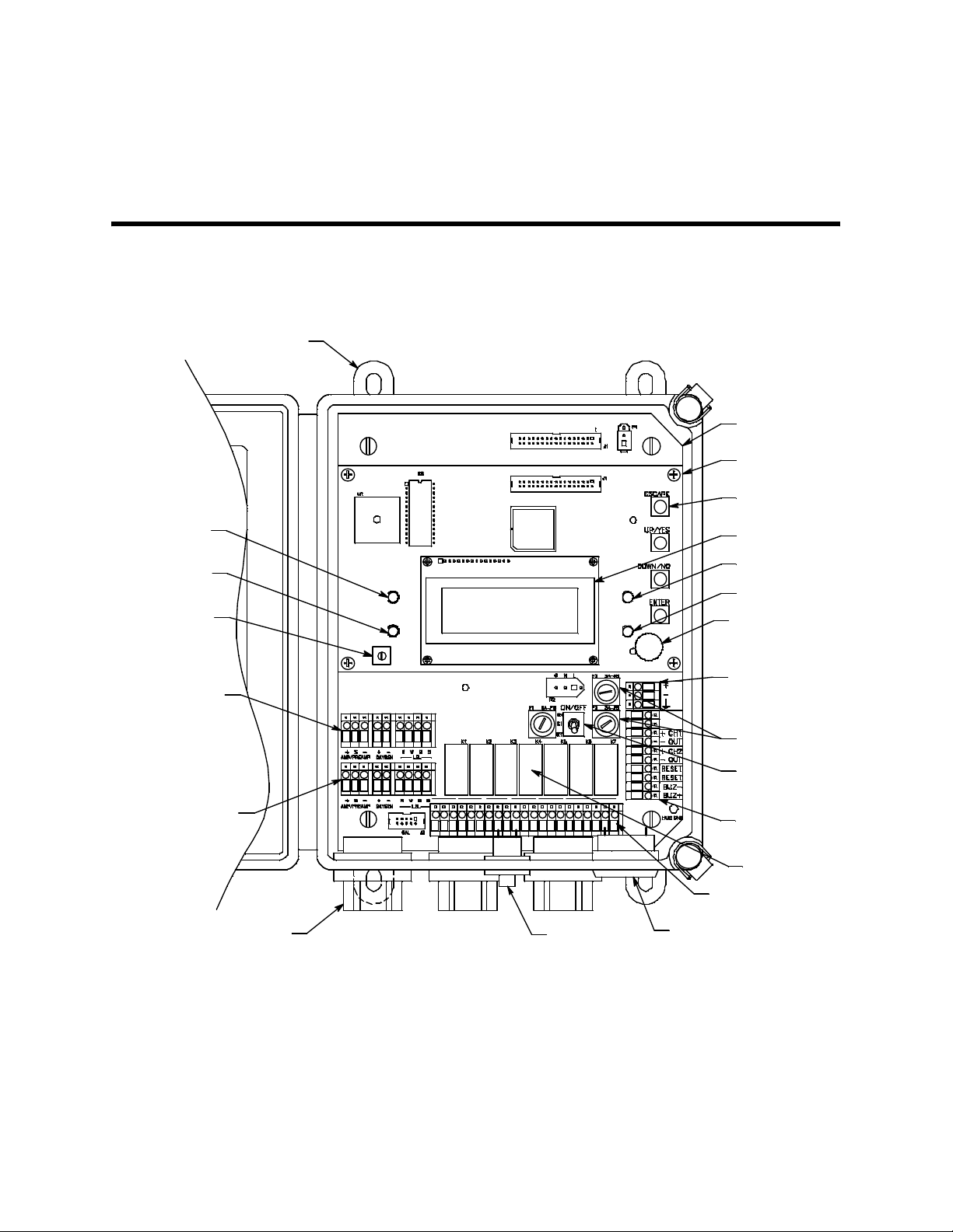
Chapter 2: Description
p
Overview
This chapter describes external and internal components of the 12 VDC
Beacon 200.
Mounting F oot, 4 X
Alarm 2
LED
Alarm
1LED
Display
Contra st
AdjustPot
Detector /
Transm itter
Terminal Strip,
Channel 1
Detector/
Transm itter
Terminal Strip,
Channel 2
ConduitHub (3X)
CH1-A1
NO NC C
CH1-A2
NO NC C
CH2- A1
NO NC C
NO NC CNO NC C
Reset
Switch
COM-A 2COM-A1CH2-A2
NO NC C
COM-FAIL
NO NC C
FACTORY
WIRED
Buzzer
MainPCB
Display PC B
Program
Button(4)
Display
Fail LED
Pilot LED
But ton
Repeater
Buzzer
DC In
Terminal
Strip
Fuses, DC
Power Switch
Controller
Terminal Stri
Relays
Alarm Terminal
Strip
Figure 1. 12 VDC Beacon 200 Component Location
4 • 12 VDC Beacon 200 Operator’s Manual
Page 9

External Description
This section describes the housing and all external components of the 12
VDC Beacon 200. For the purposes of this description, the housing door is
considered the front of the monitor.
Housing
The 12 VDC Beacon 200’s fiberglass housing is weather- and corrosionresistant. It is suitable for installation where general purpose equipment is
in use. The housing door is hinged on the left side and is secured by two
latches on the right side. The display screen and status lights are visible
through windows in the housing door. Four mounting feet are attached to
the back of the housing (one at each corner). The mounting feet allow you
to install the housing to a vertical surface. Three conduit hubs on the
bottom of the housing are for external wiring connections.
CAUTION: To avoid electrical inte rference, do not ro ute detect or head and
power wiring through the same conduit hub.
Reset Switch
The reset switch i s on the bottom of th e ho usi ng . I t i s in front of the conduit
hubs. The reset switch serves three functions:
• Resets the alarm circuits for “latched” alarms after an alarm 1 or alarm 2
condition passes.
You can set each channel for latched or self-resetting alarms in the
Channel Control & Setup Program.
• Silences the bu zzer d ur ing an alarm 1 or ala rm 2 con di ti o n. You canno t
silence failure alarms.
• Displays and resets the minimum and maximum gas concentration
values.
Buzzer
The buzzer is on the botto m of the housi ng. It is on the far r ight. The buzze r
sounds audible alarms to warn you of gas alarms and in strument failures.
12 VDC Beacon 200 Operator’s Ma nual • 5
Page 10
Internal Description
This section describes the intern al componen ts of the 12 VDC Beaco n 200.
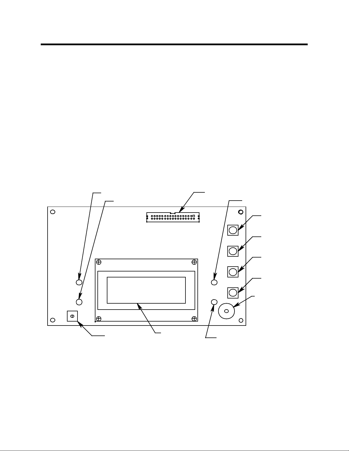
Display Printed Circuit Board (PCB)
The display PCB is mou nted to the p ower supply mo unting plate which is in
turn mounted to t he ma in PCB. The power su pply mo unting p late an d main
PCB are described below. The display PCB includes the displ ay, the status
lights, and the program buttons.
Display
The display simultaneously indicates the channel number, current gas
reading, measuring unit, and target gas of all active channels.
The display also indicates messages, settings, and other data when you
are operating the instrument programs.
ALARM 2 Light
ALARM 1 Light
Display Contrast
Adjust Pot
Display Screen
Display Cable Connector
FAIL Light
J1
PILOT Light
Figure 2. Display Board Component Location
ESCAPE
Button
UP/YES
Button
DOWN/NO
Button
ENTER
Button
Button Repeater
Buzzer
6 • 12 VDC Beacon 200 Operator’s Manual
Page 11

Status Lights
The 12 VDC Beacon 200 incl udes four status lights that indicate the current
status of the monito r. The status lights a re to the l eft and righ t of the display
(see Figure 2).
• Pilot Light. The pilot light is on when the 12 VDC Beacon 200 is
receiving incomi ng pow er.
• Fail Light. The fail light turns on when the 12 VDC Beacon 200 is
experiencing a fa il co nd i tion. A fail condition can be caused by a failure
within the 12 VD C Be acon 200 o r d etector he ad(s) wir ed to the 12 V DC
Beacon 200. See “C ha pter 7: Maintenance” o n page 37 for instructions
to respond to a fail condition.
• Alarm 1 Light. The alarm 1 ligh t is on wh en t he 12 V DC Beaco n 200 i s
experiencing an alarm 1 gas condition.
• Alarm 2 Light. The alarm 2 ligh t is on wh en t he 12 V DC Beaco n 200 i s
experiencing an alarm 2 gas condition.
Program Buttons
The 12 VDC Beacon 200 includes four program buttons that allow you to
enter the instrument programs, navigate through the programs, update
instrument and channel settings, and save changes to the program
settings. When a program button is pressed, a buzzer located on the
display PCB beeps. The program buttons are near the right edge of the
display PCB (see Figure 2).
Table 2: 12 VDC Beacon 200 Program Button Functions
Button Function
ESCAPE • Moves back ward through the progr am menus
• Cancels changes you make in the program menus
• Enters the Channel Control and Setup program (press with the ENTER button)
UP/YES • Accepts the displayed setting and proceeds to the next setting
• Changes the displayed setting
• Enters the Calibration program (press with the ENTER button)
DOWN/NO • Allows you to update the displayed setting
• Changes the displayed setting
ENTER • Saves changes you make in the programs
• Enters the Channel Control and Setup program (press with ESCAPE button)
• Enters the Calibration program (press with the UP/YES button)
12 VDC Beacon 200 Operator’s Ma nual • 7
Page 12

Main PCB
The main PCB is mounted inside the housing. The power supply mounting
plate is mounted to the main PCB with four standoffs and the display PCB
is mounted to the power supply mounting plate with four standoffs. The
main PCB includes the terminal strips, relays, fuses, and power switch.
Terminal Strips
The 12 VDC Beacon 200 includes four terminal strips for ext ernal wiring
connections. See “Wi ring the 12 VDC B eac on 20 0” on p a ge 13 for detailed
wiring procedures.
• Detector/Transmitter Terminal Strips. Two detector/transmitter
terminal strip s are locate d near the bo ttom lef t corne r of the mai n circuit
board (see Figure 1). These two 9-point terminal strips facilitate wiring
connections to the detectors or transmitters. Although each terminal
strip can accommodate several different detector head models, only
one detector h ead at a time ma y be wi red per channel . The top term inal
strip is for channel 1 and the bottom terminal strip is for channel 2.
• Alarm Terminal Strip. The alarm terminal strip is located along the
bottom edge of the main circuit board (see Figure 1). This 21-point
terminal strips facilitates wiring connections to external alarm devices
(horn, strobe, etc.). Terminals are provided for individual channels as
well as common alarm relay contacts.
• Controller T e rminal S trip. The 10-point controller terminal strip is near
the lower right edge of the main circuit board (see Figure 1). The
controller terminal strip facilitates various interna l and external wiring
connections. Table 3 lists the function of each terminal.
T able 3: Terminal Assignments for the Controller Terminal Strip
Terminal Connects to:
NOT USED (top terminal) not used
NOT USED (bottom terminal) not used
+ CH1 OUT + connection of 4 - 20 mA output, channel 1
- CH 1 OUT - connection of 4 - 20 mA output, channel 1
+ CH2 OUT + connection of 4 - 20 mA output, channel 2
- CH2 OUT - connection of 4 - 20 mA output, channel 2
RESET (2) Reset switch (factory-wired)
BUZ-/BUZ+ Internal buzzer (factory-wired)
8 • 12 VDC Beacon 200 Operator’s Manual
Page 13
• DC In T erminal S trip. The DC in terminal strip is a 3-point terminal strip
Channel 2, Alarm 2
located above the controller terminal strip (see Figure 1). It facilitates
wiring from a 12 VDC power source. Table 4 lists the function of each
terminal.
T a ble 4: Terminal Assignments for the AC In Terminal Strip
Terminal Connects to:
12 VDC + + wire from 12 VDC power source
12 VDC - - wire from 12 VDC power source
Earth ground
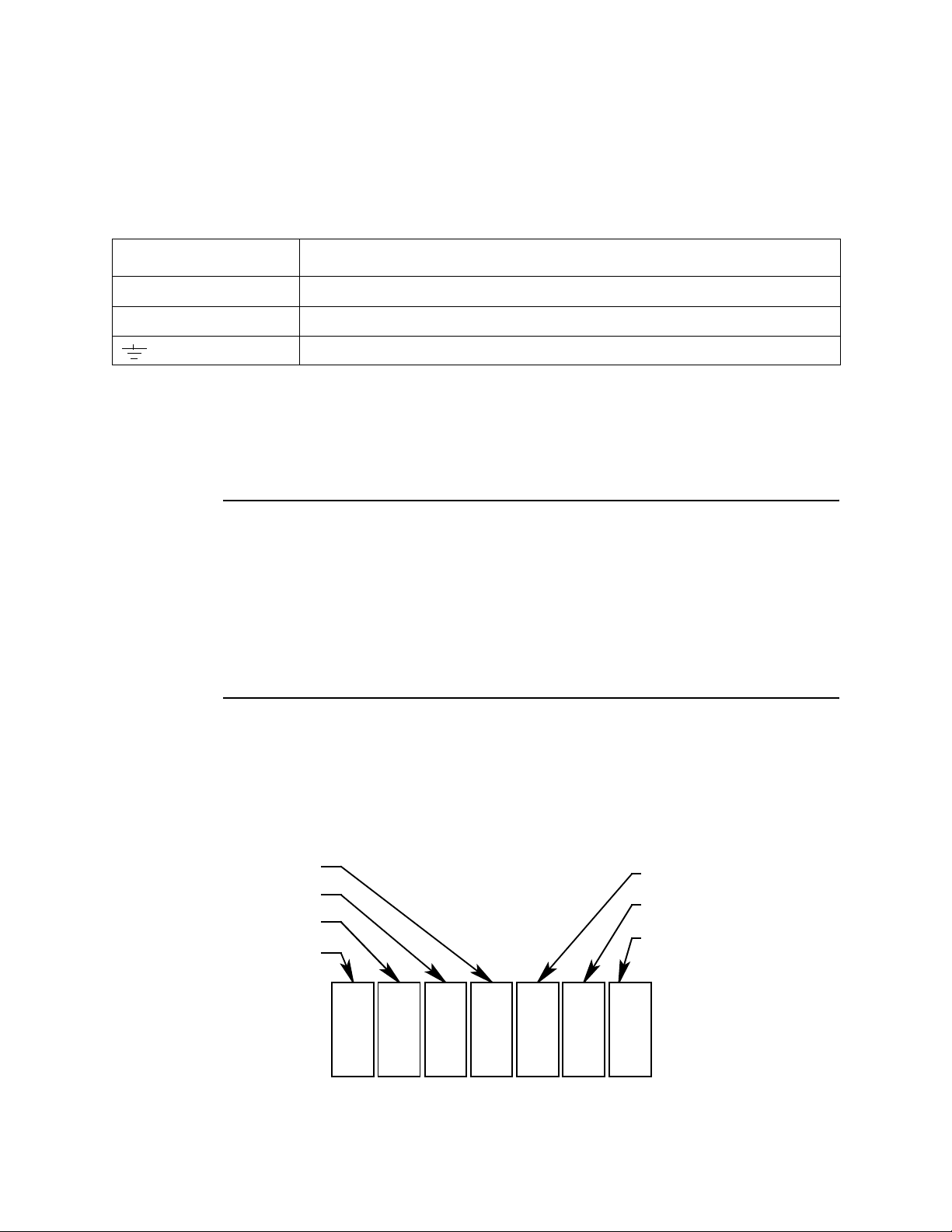
Relays
The 12 VDC Beacon 200 includes four channel relays (two per channel)
and three common rela ys. Both sets of rela ys are single-p ole, double-thro w
(SPDT) and are rated for 10 amps at 250 VAC (resistive).
NOTE: You can select normally energized (NE) or normally de-energized
(NDE) settings for ea ch channel in th e Channel Co ntrol and Setup
program. This section describes the default setting : normally deenergized.
The alarm 1 and alarm 2 common relays are factory-set as NDE
and the fail common relay is factory-set as NE. The alarm 1, alarm
2, and fail common relays’ NE/NDE settings are not useradjustable.
• Channel relays. The four channel relays are above the alarm terminal
strip (see Figure 1). These relays are dedicated to specific channels
and alarm levels.
For example, the channel 1, alarm 1 relay energizes if channel 1
recognizes an alarm 1 condition. Figure 2 below illustrates the
allocation of the channel relays.
Common Alarm 1
Channel 2, Alarm 1
Channel 1, Alarm 2
Channel 1, Alarm 1
Common Alarm 2
Common Fail
K5 K6 K7
K1 K2 K3
K4
Figure 3. 12 VDC Beacon 200 Channel Relay Allocation
12 VDC Beacon 200 Operator’s Ma nual • 9
Page 14

NOTE: The alarm 2 channel relays may be set to operate as individual
channel fail relays. See “Configure Channel Settings Menu” on
page 30 for instructions.
• Common relays. The three common relays , alarm 1, alarm 2, and fail,
are to the lef t of th e controlle r terminal strip (see Figu re 1). These rela ys
are common for both channels.
For example, the al arm 1 common rela y energizes if either channel 1 or
channel 2 recognizes an alarm 1 condition.
Fuses
There are two DC fuses that are used in the 12 VDC Beacon 200. They are
located directly to the left of the controller terminal strip. They cut off the
incoming DC power in the event of a short circuit or other electrical fault
which causes a high current draw in the 12 VDC Beacon 200. They are
housed in vertical fuse holders and are held in the holder by a quarter turn
cover. They are labelled as F2 (top fuse) and F3 (bottom fuse) on the PCB
silk-screen and are rated at 3 A, 250 V.
A third fuse located to the left of the power switch is labelled F1. This fuse
is not used in this version of the Beacon 200.
Power Switch
The power switch is located above the relays and to the left of the DC fuses
(see Figure 1). The power switch turns the incoming DC power source on
and off at the 12 VDC Beacon 200. When the switch is up, the power
switch is on.
Power Converter
The power converter is mounted to the power supply mounting plate with
standoffs. The power supply mounting plate is located behind the display
PCB and is mounted to the main PCB with fo ur standoffs. The power
converter takes 12 VDC voltage supplied to the 12 VDC Beacon 200 and
converts it to 24 VDC which is used to run the 12 VDC Beacon 200.
10 • 12 VDC Beacon 200 Operator’s Manual
Page 15

Chapter 3: Installation and Start Up
Overview
This chapter de scribes proced ures to mount the 1 2 VDC Beacon 200,
make wiring connections to the monitor, and start up the monitor.
WARNING: Perform all installation and start-up procedures in a
“fresh air” environment (known to be free of combustible
gas, toxic gas, and of normal oxygen content). The 12
VDC Beacon 200 is not in operation as a gas monitoring
system until the start-up procedure is complete.
Mounting the 12 VDC Beacon 200
Perform the following procedure to install the 12 VDC Beacon 200 at the
mounting site.
12 VDC Beacon 200 Operator’s Manual • 11
Page 16
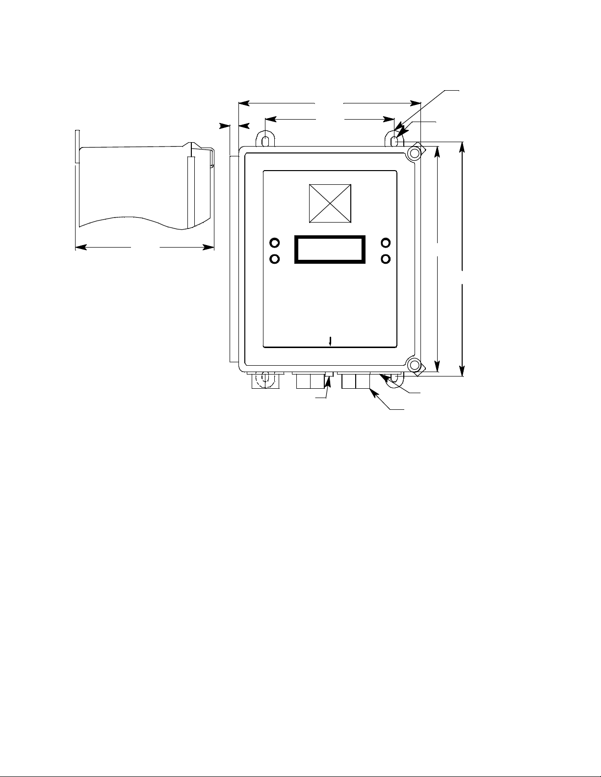
X
.41
8.50
6.00
Mounting
Feet, 4X
Ø.31x.50slot, 4
FAIL
10.50
PILOT
10.94
Buzzer
3/4 ConduitHubs (4X)
6.45
ALARM 2
ALARM 1
BEACON 200
Reset Switch
GAS MONITOR
RESET
Figure 4. 12 VDC Beacon 200 Outline and Mounting Dimensions
1. Select the mounting site. When you select the mounting site consider
the following factors:
• Is a 12 VDC power source availa ble?
• Is there enough room to open the housing door and make wiring
connections through the conduit hubs at the bottom of the housing?
• Are the display screen and status lights visible?
2. Close and latch the housing door.
3. Position t he monitor on a vertical surface at e ye level (4 1/2 to 5 feet
from the floor).
4. The 12 VDC Beacon 200 is shipped with the mounting feet positioned
behind the housing. Loosen the screws that se cure the feet to the
housing, rotate the feet to their mounting position (as shown in
Figure 4), then tighten the screws.
5. Insert 1/4 in. or 5/16 in. screws through the slot s in the mounting fe et at
each corner of the housing to secure the housing to the mounting
surface (see Figure 4).
12 • 12 VDC Beacon 200 Operator’s Manual
Page 17

Wiring the 12 VDC Beacon 200
This section de scribes procedures to connect the 12 VDC power source,
external alarm(s), a recorder, and detector head(s). See Figure 5 for a
general wiring diagram of all external wiring to the 12 VDC Beacon 200.
TypicalDetector/Transmitter Terminal
Strip Wiring
Only one detector or transmitter can be
wire d to Ch1 or Ch2 at a time. See detector
head wiring diagram for specific wi ring.
CHANNEL 1
+ S
OXYGENAMP/PREAMP
+
LEL
R W G B
Controller Termi nal Strip
Wiring
Ch an ne l 1 Rec or d er
1K M ax Impedance
Ch an ne l 2 Rec or d er
1K M ax Impedance
Reset Switch
(Factory Wired)
Buzzer
(Factory Wired)
4- 2 0mA Ou t
4- 2 0mA Ou t
In Te rminal St ri p Wir i ng
DC
+
12 V
DC
NOT
USED
+
CH1
OUT
+
CH2
OUT
RESET
RESET
BUZ
BUZ +
- DC GROUND
FB (4-2 0 mA)
+ 24 V
CHANNEL 2
AMP/PREAM P OXYGEN
+ S
+
FB (4-2 0 mA)
+ 24 V
Green
Whit e
R W G B
Oxygen
Detector
3-W i r e 4- 20 ma
Transmitter
LEL
Black
Green
White
2-W i r e 4- 20 ma
Transmitter
Red
LE L De t e c tor
ALARM
DEVICE
POWER
CH1-A1
NO NC C
Typical Alarm Relay Termina l Strip
Wiring
CH2-A1CH1-A2
NO NC C NO NC C
CH2-A2
NO NC C
COM-A1 COM-FAILCOM-A2
Alarm Devices
Contact Rat ing of 10 Am ps at 115/
220 V~ Res i stive or
10A @ 30V Resistive for
Each Set of Ala r m Re lay
Contacts.
NO NC C NO NC CNO NC C
Figure 5. 12 VDC Beacon 200 General External Wiring Diagram
12 VDC Beacon 200 Operator’s Manual • 13
Page 18

The power converter, reset switch, and alarm buzzer are all factory wired.
MAIN PCB
Converter
Power
TB1
RESET SWITCH
BUZZER
P2
P1
+
12 V
DC
NOT
USED
+
CH1
OUT
+
CH2
OUT
RESET
RESET
BUZ
BUZ +
Figure 6. 12 VDC Beacon 200 Factory Wiring Diagram
WARNING: Make all connections to the 12 VDC Beacon 200 before
you connect the DC power source. Before you make any
wiring adjustments, always verify that all power sources
are not live.
Connecting the DC Power Source
Perform the following functions to connect the 12 VDC Beacon 200 to DC
power.
NOTE: Be sure to turn off the 12 VDC Beacon 200 before connecting or
disconnecti ng it from the 12 VDC power source.
1. Turn off, unplug, or disconnect all incoming power to the 12 VDC
Beacon 200.
2. Open the housing door, then place the power switch in the OFF
position.
14 • 12 VDC Beacon 200 Operator’s Manual
Page 19

3. Install an appropriately rated cable bushing or conduit in an unused
conduit hub on the bottom of the 12 VDC Beacon 200 housing.
4. Guide the power wiring th rough the se lected condu it hub on t he bottom
of the 12 VDC Beacon 200 housing.
CAUTION: Do not route the power wiring and detector head wiring
through the same conduit hub. The power wiring may disrupt
the transmission of the detector signal to the 12 VDC Beacon
200.
5. Connect the leads from the po wer su pp ly to th e DC In te rmin al st rip a s
shown in Figure 7.
12 VDC Pow er
Source
Connecting External Alarms
Perform the following procedure to connect external alarm devices to the
12 VDC Beacon 200.
NOTE: The alarm termina l strip includes terminals for channel alarms
1. Turn off or unplug power to the 12 VDC Beacon 200.
2. Open the housing door, then place the power switch in the OFF
position. Locate the alarm terminal strip (see Figure 1).
+
-
Figure 7. Power Wiring
and common alarms. Channel alarms are activated by one
particular channel. Common alarms are ac tivated by eith er of the
two channels.The example used in this procedure describes
connecting an external alarm devi ce to one of the channel alarm
terminals: the channel 1, al arm 1 term inal s.
12 VDC In
Term inal Strip
3. Install an appropriately rated cable bushing or conduit in an unused
conduit hub on the bottom of the 12 VDC Beacon 200 housing.
4. Guide the wiring of the external alarm device through the selected
conduit hub on the bottom of the 12 VDC Beacon 200 housing.
CAUTION: Do not route the external alarm wiring and detector head
wiring through the same conduit hub. The external alarm
wiring may disrupt the transmission of the detector signal to
the 12 VDC Beacon 200.
12 VDC Beacon 200 Operator’s Manual • 15
Page 20

5. Connect the leads from the external alarm device and power to the
alarm terminals as shown in Figure 8.
External Alarm
Device
6. Repeat steps 4 and 5 for additional external alarm devices.
Connecting a Recorder
Perform the following procedure to connect an analog recording device to
the 12 VDC Beacon 200. Th e outpu t at the re corder o utput te rmina ls is a 4
- 20 mA signal that is proportional to the detection range of the applicable
detector head.
CH1-A1
NO NC C
+ (H)
-(N)
Figure 8. Typical External Alarm Wiring
Beacon 200 Alarm
Terminal Strip
External Power
Source
1. Turn off or unplug power to the 12 VDC Beacon 200.
2. Open the housing door, then place the power switch in the OFF
position. Locate the recorder output terminals on the controller terminal
strip (see Figure 1).
3. Install an appropriately rated cable bushing or conduit in an unused
conduit hub on the bottom of the 12 VDC Beacon 200 housing.
4. Guide the wiring from the recording device through the selected
conduit hub on the 12 VDC Beacon 200.
16 • 12 VDC Beacon 200 Operator’s Manual
Page 21

5. Connect the wires from the recording device to the recorder output
terminals as shown in Figure 9.
Recording Device
#1, 1Kohm Max
Impedance
Recording Device
#2, 1Kohm Max
Impedance
Connecting RKI Detector Heads
Perform the following proce dure to co nnect a n RKI dete ctor h ead to t he 12
VDC Beacon 200.
1. Turn off or unplug power to the 12 VDC Beacon 200.
2. Open the 12 VDC Beacon 200 housing door and place the power
switch in the off position.
3. See the detector head instruction manual for instructions on how to
connect wires to the detector head.
+
+
Figure 9. Recorder Output Wiring
+
+
CH1
OUT
CH2
OUT
4. Install an appropriately rated cable bushing or conduit in an unused
conduit hub on the bottom of the 12 VDC Beacon 200 housing.
5. Route the wir es in conduit or shielded cable from the detector head
through the selected conduit hub into the 12 VDC Beacon 200. See
Table 5 below for wire size and distance guidelines.
Unshielded twisted pair cable in condu it or shielded twisted pair cable
is recommended f or all the direct conn ect detector heads. For the LEL
detector, pair the R & B wires and the W & G wires. Shielded cable or
wires in conduit are recommended for the 2-wire and 3-wire 4 - 20 mA
transmitters.
6. Connect the wires from the det ector head to the appropriate det ector/
transmitter terminals. The top detector terminal strip is for channel 1
and the bottom one is for channel 2. See the detector head instruction
manual for controller terminal connections.
CAUTION: Do not route power and det ector head wiring through the same
conduit hub. The p ower wiring may disr upt th e transmission of
the detector head’s to the 12 VDC Beacon 200.
12 VDC Beacon 200 Operator’s Manual • 17
Page 22

T able 5: Wire Size Guidelines for RKI Detector Head Wiring
Number of
Detector Head Type
Direct Connect LEL 4 500 ft. 1,000 ft. 2,000 ft.
Direct Connect Oxygen 2
Direct Connect H2S 2
Direct Connect CO 2
Direct Connect Cl2 2
Direct Connect SO2 2 500 ft. 1,000 ft. 2,000 ft.
2-Wire 4 - 20 mA Transmitter 2 2,500 ft. 5,000 ft. 8,000 ft.
3-Wire 4 - 20 mA Transmitter 3 2,500 ft. 5,000 ft. 8,000 ft.
Wires to
Controller
Max Distance to
Controller w/18
Gauge Wire
500 ft. 1,000 ft. 2,000 ft.
500 ft. 1,000 ft. 2,000 ft.
500 ft. 1,000 ft. 2,000 ft.
500 ft. 1,000 ft. 2,000 ft.
Max Distance
to Controller w/
16 Gauge Wire
Max Distance to
Controller w/14
Gauge Wire
Connecting User-Supplied 4 - 20 mA Transmitters
The 12 VDC Beacon 200 ma y be used with a user suppli ed 2-wire or 3-wire
4 - 20 mA transmitter which runs on 24 VDC. When this is done, the 12
VDC Beacon 200 is normally setup at RKI Instruments with the following
channel parameters: unit of measure, item name, and full scale. For
example, “PSI AIR” with a full scale of 10 PSI.
Perform the following procedure to connect a 4 - 20 mA transmitter, which
you supply, to the 12 VDC Beacon 200.
1. Turn off power to the 12 VDC Beac on 200 at the power s ource.
2. Open the 12 VDC Beacon 200 door and turn off the power switch.
3. See the transmitter’s instruction manual for instructions on how to
connect wires to the transmitter.
4. Install an appropriately rated cable bushing or conduit in an unused
conduit hub on the bottom of the 12 VDC Beacon 200 housing.
5. Route the wires from the transmitter through the selected conduit hub
into the 12 VDC Beacon 200.
6. Connect the wires from the transmitter to the appropriate detector/
transmitter terminals. The top detector terminal strip is for channel 1
and the bottom one is for channel 2. See the transmitter instruction
manual for contro ller terminal connections. Figure 10 below illustrates
typical transmitter wiring connections.
18 • 12 VDC Beacon 200 Operator’s Manual
Page 23

CAUTION: Do not route power and transmitter wiring through the same
conduit hub. The p ower wiring may disr upt th e transmission of
the transmitter’s signal to the 12 VDC Beacon 200.
3-Wire Connection
AMP/PREAMP
+ S
OXYGEN
+
-
(DC GROUND)
RW G B
FB (4-20 mA)
+ 24 VDC
Figure 10. Generic 4 to 20 mA Transmitter Output Wiring
LEL
3-Wire 4-20 ma
Transmitter
2-Wire Connection
AMP/PREAMP OXYGEN
+ + S
FB (4-20 mA)
+ 24 VDC
RW G B
LEL
2-Wire 4-20 ma
Transmitter
12 VDC Beacon 200 Operator’s Manual • 19
Page 24

Starting Up the 12 VDC Beacon 200
Perform the following procedure to place the 12 VDC Beacon 200 into
normal operation.
1. Complete the mounting and wiring procedures describe d e ar l ie r in this
chapter.
2. Complete all installation procedures described in the detector head or
user supplied 4-20 mA transmitter i nstruction manual.
3. Verify that al l wiring co nnections are co rrect and se cure and that the 12
VDC Beacon 200’s power switch is in the OFF position.
4. Plug in or turn on the 12 VDC power source.
5. Place the 12 VDC Beacon 200’s power switch in the ON position. RKI
INSTRUMEN T S BE A CON 200 appears on the display for a few
seconds, then WARMING UP appears for each active channel. The
warm-up period will last for one minute.
NOTE: To prevent unwanted alarms during warm up, the alarm circuits
are not active while the WARMING UP message is displayed.
6. Verify that the PILOT light is on. If the PILOT light is not on, see
“Troubleshooting” on page 45.
7. Perform the start-up procedure for each detector head or user s upplied
4 - 20 mA transmitter as described in the detector head or transmitter
instruction manual.
20 • 12 VDC Beacon 200 Operator’s Manual
Page 25

Chapter 4: Operation
Overview
This chapter describes the 12 VDC Beacon 200 in normal operation. This
chapter also describes the 12 VDC Beacon 200 in alarm 1, alarm 2, and fail
conditions and suggests response to these conditions.
Normal Operation
Normal operation is defined as follows:
• The start-up procedure is complete.
• The 12 VDC Beacon 200 is not indicating an alarm 1, alarm 2, or fail
condition.
• The 12 VDC Beacon 200 is not running the Channel Control & Setup or
Calibration Programs.
During normal op er ati o n, t he 12 VDC Beacon 200 simul taneously displays
the current gas reading, unit of measure, and target gas for each active
channel.
:
1
2
:
0
20.9
%
%
E
L
Oxy
L
CH4
g
e
n
The PILOT light is on during normal operation indicating that the 12 VDC
Beacon 200 is receiving incoming power.
12 VDC Beacon 200 Operator’s Manual • 21
Page 26

Recorder Output Operation
The output at the recorder output terminals is a 4 - 20 mA signal for each
active chann el that is proportional to the detection range of the channel. A
channel that is set as CHANNEL NOT USED or CHANNEL DISABLED in
the Channel Control & Setup Program (see “Chapter 5: Channel Control
and Setup Program” on page 28) has an output of 0 mA.
There are several special circumstances where the recorder output will
behave as follows:
• When a channel is in WARMUP after the 12 VDC B eacon 200 i s tu rned
on, the recorder output will be at 4 mA.
• If the 12 VDC Beacon 200 is being powered by a battery and is in low
battery alarm, the recorder output for each channel will b e 0 mA.
• When a channel is added or a channel type change d, the display will
indicate NEEDS CALIBRATION for that channel when the 12 VDC
Beacon 200 is first turned on and will cont inue to indicate this until the
channel is calibrated. In this situation, the recorder output will be at 3.2
mA until the channel is calibrated.
• If a channel goes into a fail condition, the recorder output will be 0 mA.
• If you enter any of the instrument programs, such as the Calibration
Program, the recorder output will hold at the value it was at when you
entered the program was entered until you return to normal operation.
22 • 12 VDC Beacon 200 Operator’s Manual
Page 27

Alarm Indications
This section describes the 12 VDC Beacon 200 in alarm 1, alarm 2, and fail
conditions and suggests response to these conditions. Table 6 below lists
the alarm indications for each condition.
NOTE: The 12 VDC Beacon 200 includes alarm on and alarm off dela y
settings for each channel and level of gas alarm. The alarm
indications described in this section operate according to the
factory set delay sett ings. See “Con figure Channe l Settings Menu”
on page 30 for all the factory settings.
Table 6: Visual and Audible Alarm Indications
Condition Cause Visual Indication(s)
1
Alarm 1
Alarm 2
Fail • Disconnected or misconnected
Low Battery
NOTE: Under typical operating conditions, there will be no low power alarm. Most 12 VDC power sources’ output voltage
will decrease too quickly in a low power condition for the 12 VDC Beacon 200 to recognize a low power condition before it
shuts down.
1
Increasing (decreasing for O2) gas
reading at or above (below for O
alarm 1 setpoint
Increasing gas reading at or above the
alarm 2 setpoint
detector wiring
• Display reading below -10% of full
scale or lower
• Defective components
Dead 12 VDC battery. • FAIL light is on
) the
2
• ALARM 1 light is on
• Gas reading flashes and
alternates with
message
• Strobe/horn turns on
• ALARM 2 light is on
• Gas reading flashes and
alternates with
message
• FAIL light is on
•
FAIL message flashes in
place of gas reading
•
SUPPL Y VOL TAGE IS TOO
LOW
LOW POWER
STANDBY
actual voltage of incoming
DC power
message and
ALARM-1
ALARM-2
Audible
Indication
Pulsing tone
Pulsing tone
Steady tone
None
1
If the 12 VDC Beacon 200 is in both an alarm 1 and an alarm 2 condition, both alarm lights are on and the
*
display alternates between the gas reading and the ALARM-1 ALARM-2 message.
12 VDC Beacon 200 Operator’s Manual • 23
Page 28

NOTE: You can select normally energized (NE) or normally de-energized
(NDE) channel relay settings in the Channel Control & Setup
menu. The following sections describe the default setting for the
channel relays which is NDE.
Common alarm 1 and alarm 2 relays are factory-set as NDE, and
the common fail relay is factory set as NE. The common relays’
NE/NDE settings are not user-adjustable.
Alarm 1 Condition
This section describes the audible and visual indications for an alarm 1
condition and sugge s t s re spo nse to an al ar m 1 condit ion .
Alarm 1 Condition Indications
When the gas reading of an active channel reaches the alarm 1 setpoint,
the 12 VDC Beacon 200 senses an alar m 1 conditio n. The 12 VDC B eacon
200 alerts you to an alarm 1 condition as follows:
• The ALARM 1 light turns on.
• The gas reading in alarm 1 condition flashes and alternates with the
ALARM-1 message.
• The buzzer sounds a Pulsing tone.
• The common alarm 1 relay energizes .
• The applicable alarm 1 channel relay energizes.
Responding to an Alarm 1 Condition
This section suggests response to an alarm 1 condition.
1. Follow your established procedu r e for a low level combustible or toxic
gas condition or a decreasing oxygen content condition.
2. Oxygen alarms are self-resetting and will automatically clear when the
oxygen rises above the alarm 1 setpoint.
3. Alarms for all other gas types are latching. After the gas reading falls
below the alarm 1 setpoint, press the reset switch to reset the alarm 1
circuit. Resetting the alarm 1 circuit silen c es the bu zzer, turns off the
ALARM 1 light, resets the channel display, and de-energizes the
common and channel alarm 1 relays.
24 • 12 VDC Beacon 200 Operator’s Manual
Page 29

NOTE: To silence the buzzer while in an alarm 1 condition, press the
reset switch.
You cannot de-energize the alarm 1 relays and consequently the
strobe/horn until the gas reading falls below the alarm 1 setpoint.
Alarm 2 Condition
This section describes the audible and visual indications for an alarm 2
condition and sugge s t s re spo nse to an al ar m 2 condit ion .
Alarm 2 Condition Indications
When the gas reading of an active channel reaches the alarm 2 setpoint,
the 12 VDC Beacon 200 senses an alar m 2 conditio n. The 12 VDC B eacon
200 alerts you to an alarm 2 condition as follows:
• The ALARM 2 light turns on.
• The gas reading in alarm 2 condition continues to flash and alternates
with the ALARM-2 messages.
• The buzzer sounds a Pulsing tone.
• The common alarm 2 relay energizes .
• The applicable alarm 2 channel relay energizes.
Responding to an Alarm 2 Condition
This section suggests response to an alarm 2 condition.
1. Follow your establish ed proced ure fo r a high l evel combust ibl e or toxic
gas condition or an increasing oxygen content condition.
2. Oxygen alarms are self-resetting and will automatically clear when the
oxygen rises above the alarm 2 setpoint.
3. Alarms for all other gas types are latching. After the gas reading falls
below the alarm 2 setpoint, press the reset switch to reset the alarm
circuit. Resetting the alarm circuit turns off the ALARM 2 light, and deenergizes the common and channel alarm 2 relays .
NOTE: To silence the buzzer while in an alarm 2 condition, press the
reset switch.
You cannot de-energize the alarm 2 relays until the gas reading
falls below the alarm 2 setpoint.
12 VDC Beacon 200 Operator’s Manual • 25
Page 30

Fail Condition
This section describes the audible and visu al indication s for a fail conditio n
and suggests response to a fail condition.
Fail Condition Indications
The 12 VDC Beacon 200 senses a fail condition for any of the following:
• The detector hea d wi ring to th e 12 VDC Be acon 2 00 i s disco nnecte d or
incorrectly co nnected.
• The detector head’s detector is disconnected or incorrectly connected.
• The display reading is -10% of full scale or lower.
• The 12 VDC Beacon 200 or detector head is malfunctioning.
When the 12 VDC Beacon 200 senses a fail condition, it alerts you as
follows:
• The FAIL light turns on.
• The gas reading for the failing channel is replaced by the FAIL
message.
• The buzzer s ounds a steady tone.
• The common fail relay de-energizes.
NOTE: If you elected to use the channel’s alarm 2 relay as an individual
fail relay in the Channel Control & Setup menu, the rel ay deenergizes in a fail co ndition. S ee “Chapte r 5: Chan nel Contr ol and
Setup Program” on page 28 for a description of this setting.
Responding to a Fail Condition
This section suggests response to a fail condition.
1. Verify that the detector head wiring to the 12 VDC Beacon 200 is
correctly and securely connected.
2. Verify that the detector head’s detector is correctly and securely
connected.
3. See the troubleshooting guide in the detector head instruction manual.
Low Power Condition
Most 12 VDC power sources’ output voltage will decrease too quickly in a
low power condition for the 12 VDC Beacon 20 0 to recognize a low power
condition before it shuts down. As a result, when the 12 VDC Beacon 200
is used with a 12 VDC po wer source, there may be no low power ala rm and
26 • 12 VDC Beacon 200 Operator’s Manual
Page 31

the unit may instead shut off if the input voltage decreases below 10.8 V.
Viewing & Resetting Min/Max
Readings
The Reset switch may be used to view and reset the minimum and
maximum gas readings for the active channel(s).
1. While the 12 VDC Beacon 200 is in normal operation, press and hold
the Reset switch button for 3 seconds.
2. The display will indicate MIN / MAX Display Pres s RESET when
done viewing . . . for 5 seconds before displaying the minimum and
maximum readings for the active chann el(s). The minimum reading is
on the left and th e m axim um i s on the r ight si d e of the di splay for each
channel.
3. Press and release the Reset switch button to exit the min/max screen.
The display will indicate To RESET Min/MAX values Press and
HOLD RESET Button for 10 seconds and then return to normal
operation.
• To return to normal operation without resetting the minimum and
maximum readings, do not press the Reset switch button and allow
the unit to return to normal operation.
• To reset the minimum and maximum readings, before the unit
returns to normal operation press and hold the Reset switch button
until the display indicates Min/Max Values Have Been Reset.
Release the Reset switch button.The unit will then return to normal
operation.
12 VDC Beacon 200 Operator’s Manual • 27
Page 32

Chapter 5: Channel Control and Setup Program
Overview
The Channel Control & Setup Program allows viewing of and changes to
instrument setup parameters. It is accessed using the program buttons.
The Channel Control & Setup Program i ncludes thr ee m enus as de scribed
in Table 7.
Table 7: Channel Control & Setup Program Menus
Menu Function
Enable/Disable Channel(s) Configures channels as enabled, disabled, or not used
Configure Channel Settings Configures alarm settings, noise filter setting, and zero
suppression setting for each channel
View System Information Displays the firmware version number and the instrument
operating voltage
To enter the Channel Control & Setup Program, simultaneously press and
hold the ESCAPE and ENTER buttons f or approximately 5 seconds.
The Channel Control & Setup Program menu includes a 5-minute time-out
feature. If you do not press a but ton for 5 mi nutes, the 12 VDC Bea con 200
automatically returns to normal operation.
NOTE: If the 12 VDC Beacon 200 returns to normal operation because of
a program time-out, the active channels enter a warm-up period
just as they do when the unit is first turned on.
If you are installing a new system, the channels have been setup
at the factory for the ordered detector he ads. Use the Channel
Control & Setup Program only if you want to disable or enable a
channel, delete a channel, or change chan ne l setti n gs. If a
channel is being added or a channel is being changed from one
type to another, contact RKI Instruments, Inc. for additional
documentation required to define the channel type.
28 • 12 VDC Beacon 200 Operator’s Manual
Page 33

Enable/Disable Channel(s) Menu
1. From normal operation, simultaneously press and hold the ESCAPE
and ENTER button s for ap pr oxim ately 5 seconds to enter t he C h ann el
Control & Setup Program. Release the buttons when the Control &
Setup Program Proceed? [YES] or [NO] message appears on the
display screen.
2. Press the UP/YES button to continue.
3. Press the UP/YES or DOWN/NO button until the 1) Enable/Disab le
Channel(s) message appears on the display screen, then press the
ENTER button.
4. Use the UP/YES and DOWN/NO buttons to select the channel you
want to enable or disable, then press the ENTER button.
5. Press the DOWN/NO button. The CHANNEL USAGE setting displays
on the display screen.
6. Use the UP/YES and DOWN/NO buttons to display the setting you
want, then press the ENTER button to select the setting. The table
below describes the three available settings.
T a ble 8: 12 VDC Beacon 200 Channel Usage Settings
Setting Description
CHANNEL ENABLED The 12 VDC Beacon 200 displays gas readings and initiates gas and channel failure
alarms when appropri ate.
Use this setting for normal operation when the channel has a detector head wired to
it.
CHANNEL DISABLED The 12 VDC Beacon 200 displays
alarm circuit is
Use this setting when the channel has a detector head wired to it, but gas readings
and alarms are not required for the channel (for example if the detector head requires
maintenance or is malfunctioning).
CHANNEL NOT USED The 12 VDC Beacon 200 leaves the chann el bla nk on the display scree n.
Use this setting when the channel does
not active.
DISABLED for the channel and the ch annel’s
not have a detector head wired to it.
7. Press the ESCAPE button, then press the DOWN/NO button to return
to normal operation.
12 VDC Beacon 200 Operator’s Manual • 29
Page 34

Configure Channel Settings
Menu
This section describes how to view and change channel parameters for the
installed gas channels.
1. Simultaneously press and hold the ESCAPE and ENTER buttons for
approximately 5 seconds to enter the Channel Control & Setup
Program. Release the buttons when the Control & Setup Program
Proceed? [YES] or [NO] message appears on the display screen.
2. Press the UP/YES button to continue.
3. Press the UP/YES or DOWN/NO button until the 2) Configure
Channel Setting(s) message appears on the display screen, then
press the ENTER button.
4. Use the UP/YES and DOWN/NO buttons to select the channel for
which you want to set parameters, then press the ENTER button.
5. Press the UP/YES button until the parameter you want to set appears
on the display screen. The screen will display the current setting and
ask if it is OK.
Table 9 lists the paramete rs you can set for a channel . Table 9 also lists
the factory set value for each parameter.
NOTE: Use the ESCAPE button to go back to a previously displayed
parameter.
6. If the setting is not OK and you want to change th e it, press the DOWN/
NO button. The parameter is now adjustable.
7. Use the UP/YES or DOWN/NO button to update the parameter, then
press the ENTER button to continue.
8. Repeat steps 5 through 7 to set any other channel paramet ers.
9. Press the UP/YES button until the following message appears on the
display screen.
Con f iguration for
CHANNEL 1
has nbee
eSav Se t t ings
completed
[
Y
?
/N
]
30 • 12 VDC Beacon 200 Operator’s Manual
Page 35

10.Press the UP/YES button to save the configuration. The screen will
then return to the Channel Control & Setup menu.
11. To view or ch ange the Channel 2 s ettings, scroll to the Configure
Channels Menu an d repeat steps 4 through 10.
12.To exit the Channel Control & Setup menu, press ESCAPE to return to
the screen which asks Control & Setup Program Proceed? [YES] or
[NO].
13.Press the DOWN/NO button to return to normal operation.
Table 9: Channel Setting Parameters
Parameter
(Factory-Set Value)
ALARM-1 Level
(See the Beacon 200 Detector Head
Specification Sheet for the detector
head installed on this channel)
ALARM-1 ON DELAY
(1 sec)
ALARM-1 OFF DELAY
(0 sec)
ALARM-1 (activation)
(DECREASING for oxygen channels,
INCREASING for all other channel
types)
ALARM-1 Relay (action)
(NORMALLY DE-ENERGIZED)
ALARM-1 Relay (reset)
(SELF RESETTING for oxygen,
LATCHING for all other channel types)
Description
The gas read ing at which the 12 VDC Beacon 200 initiates an alarm 1
condition for this channel.
The amount of time the 12 VDC Beacon 200 delays activation of the
alarm 1 circuit once an a l arm 1 condition is initiated.
The amount of time t he 1 2 VDC Beacon 200 del ay s tu rni ng o f f th e al arm
1 circuit once an alarm 1 condition passes.
Indicates if the alarm 1 circuit is activated by gas readings
DECREASING to the ALARM-1 Level.
or
If set as
energized in normal operation and energizes when an alarm 1 condition
is initiated.
If set as
energized in normal operation and de-energizes when an alarm 1
condition is initiated.
If set as
alarm 1 circuit after the alarm 1 condition passes.
If set as
resets the alarm 1 circuit after the alarm 1 condition passes.
NORMALL Y DE-ENERGIZED, the c hanne l’ s alarm 1 rela y is de -
NORMALLY ENERGIZED, the channel’s alarm 1 relay is
LATCHING, you must press the RESET button to reset the
SELF RESETTING, th e 12 VDC Beacon 200 automatically
INCREASING
ALARM-2 Relay (used for)
(ALARM-2 Condition)
ALARM-2 Level
(See the Beacon 200 Detector Head
Specification Sheet for the detector
head installed on this channel)
ALARM-2 ON DELAY
(2 min for oxygen, 1 sec for all other
channel types)
If set as
when an alarm 2 condition is initiated for the channel.
If set as
fail condition is initiated for the channel.
The gas read ing at which the 12 VDC Beacon 200 initiates an alarm 2
condition for this channel.
The amount of time the 12 VDC Beacon 200 delays activation of the
alarm 2 circuit once an a l arm 2 condition is initiated.
ALARM-2 Condition, the channel’s alarm 2 relay activates
FAIL Condition, the channel’s alarm 2 relay activates when a
12 VDC Beacon 200 Operator’s Manual • 31
Page 36

Table 9: Channel Setting Parameters (Continued)
Parameter
(Factory-Set Value)
ALARM-2 OFF DELAY
(0 sec)
ALARM-2 (activation)
(INCREASING)
ALARM-2 Relay (action)
(NORMALLY DE-ENERGIZED)
ALARM-2 Relay (reset)
(SELF RESETTING for oxygen,
LATCHING for all other channel types)
NOISE FILTER
(3)
Description
The amount of time t he 1 2 VDC Beacon 200 del ay s tu rni ng o f f th e al arm
2 circuit once an alarm 2 condition passes.
Indicates if the alarm 2 circuit is activated by gas readings
or
DECREASING to the ALARM-2 Level.
If set as
energized in normal operation and energizes when an alarm 2 condition
is initiated.
If set as
energized in normal operation and de-energizes when an alarm 2
condition is initiated.
If set as
alarm 2 circuit after the alarm 2 condition passes.
If set as
resets the alarm 2 circuit after the alarm 2 condition passes.
The noise filter feature helps “smooth out” jumpy or noisy signals from
the detector head. You can set the noise filter from 1 to 8.
A setting of
responds slowest to changes in the response reading.
A setting of
produces the least amount of smoothing.
NORMALL Y DE-ENERGIZED, the c hanne l’ s alarm 2 rela y is de -
NORMALLY ENERGIZED, the channel’s alarm 2 relay is
LATCHING, you must press the RESET button to reset the
SELF RESETTING, th e 12 VDC Beacon 200 automatically
8 produces the greatest amount of smoothing but also
1 responds fastest to changes in the response reading but
INCREASING
ZERO SUPPRESSION
(0.5%
oxygen for oxygen channels,
2.0% of
types)
full scale for all othe r channe l
View System Information Menu
The View System Information Menu consists of only one display screen
which indicates the version number of the firmware that is running the
instrument and the system voltage. The system voltage is the voltage that
is directly runnin g the instrument’ s circuitr y. Although 12 VDC is supplied to
this version of the Beacon 200, the system voltage will typically indicate 24
VDC because of the 12 VDC to 24 VDC converter in the 12 VDC Beacon
200.
The zero suppression feature helps prevent “jumpy” readings near the
fresh air reading.
For example, if the zero suppression setting on a %LEL channel is
and the full scale is 100% LEL, the 12 VDC Beacon 200 will display a
reading of 0% LEL for gas readings from -2% LEL to 2% LEL.
2.0%
32 • 12 VDC Beacon 200 Operator’s Manual
Page 37

Chapter 6: Input Setup Program
Overview
This chapter describes how to use the Input Setup Program to add a
channel or chang e t he cha nn el typ e of a n in stalled channel on the 12 VDC
Beacon 200. The Input Setup Program allows you to define the type of
detector head, the units and gas type, and the f ull scale for that channel.
To enter the Input Setup Program, the 12 VDC Beacon 200 must first be
off. While the 12 VD C Beacon 200 is off, pr ess and hold the ENTER butt on,
then turn on the 12 VDC Beacon 200 with the ON/OFF switch.
The Input Setup Program m enu include s a 5-minute time-out feature. If you
do not press a bu tton f or 5 m inutes, the 12 VDC Bea con 2 00 automatically
begins normal operation.
NOTE: If the 12 VDC Be acon 200 enters normal oper ation because of a
program time-out, the active channels enter a warm-up period just
as they do when the unit is first turned on.
Setting Up a New Channel or
Changing an Existing Channel
1. While the 12 VDC Beacon 200 is off, press and hold the ENTER
button, then turn on the 12 VDC Beacon 200 with the ON/OFF switch.
2. The 12 VDC Beacon 200 will beep repeatedly whi le you are holding
down the ENTER button and then the scre en will show INPUT SE TUP
PROGRAM on the top line.
3. Press the ENTER button to continue.
If you press the ESCAPE button, the unit will start-up and enter its
warm-up period.
4. Press the UP/YES or DOWN/NO button until the channel you wish to
add or change appears on the display screen, then press the ENTER
button. The detector head type screen appears.
5. The display screen indicates what type of detector head is currently
selected for that channel and asks if it is OK. Table 1 below briefly
12 VDC Beacon 200 Operator’s Manual • 33
Page 38

describes each type.
Table 10: 12 VDC Beacon 200 Detector Head Types
Detector Head Type Description
4 - 20 mA Amp [+S(-)] A 4 - 20 mA detector head is connected to the 12 VDC
Beacon 200 with 2 or 3 wi res, depending on the detector
head model, using the AMP/PREAMP +, S, and - terminals
on a detector head term inal s trip. All calib ration a djust ment s
are made at the detector head.
PreAmp [+S] A PreAmp detector head is conne cted to the 12 VD C Beacon
200 with 2 wires using the AMP/PREAMP + and S terminals
on a detector head terminal strip. A l l calibration adjustments
are made at the 12 VDC Beacon 200.
O2 Direct [+-] An O2 Direct detector head is an oxygen detector head in
which the oxygen detector is wired to the 12 VDC Beacon
200 with 2 wires using the OXYGEN + and - terminals on a
detector head terminal strip. All calibration adjustments are
made at the 12 VDC Beacon 200.
LEL Direct [RWGB] An LEL Direct detector head is a combustible gas detector
head in which the combus tible gas detect or is wired to the 12
VDC Beacon 200 with 4 wires using the LEL R, W, G, and B
terminals on a detector head terminal strip. All calibration
adjustments are made at the 12 VDC Beacon 200.
If the detector head type is not correct, press the DOWN/NO button
and continue with step 6.
If the detector head type is correct, press the UP/YES button to
proceed to t he units and gas type screen and skip to step 7.
NOTE: See the detector head operator’s manual and the Beacon 200
Detector Head Specification sheet for the detector head to
determine the detector head type.
6. Use the UP/YES and DOWN/NO buttons to scroll through the list of
detector head types until the correct one is displayed. Press the
ENTER button to accept the type.The units and gas type screen
appears.
7. If the units and gas type are not correct, press the DOWN/NO button
and continue with step 8.
If the units and gas type are correct, press the UP/YES button to
proceed to the full scale screen and skip to step 9.
8. Use the UP/YES and DOWN/NO buttons to scroll through a list of units
and gas type choices.
34 • 12 VDC Beacon 200 Operator’s Manual
Page 39

NOTE: See the Beacon 200 Detector Head Specification Sheet for the
detector head to determine t he correct units and gas type.
When the desired units and gas type appears, press the ENTER
button to accept the choice. The full scale screen appears.
One of the choices is User Will Specify. If the desired units and gas
type setting is not in the list, this setting will allow you to enter a 10
character units and gas type setting. With this choice displayed, press
the ENTER button and a screen will appear which allows you to input
the characters. Use the UP/YES and DOWN/NO buttons to select a
character and then press ENTER to accept it and continue with the
next character. When all characters have been entered, the full scale
screen will appear.
9. If the full scale setting is not correct, press the DOWN/NO button and
continue with step 10.
If the full scale setting is correct, press the UP/YES button to proceed
to the save screen and skip to step 11.
10.Use the UP/YES and DOWN/NO buttons to scroll through a list of full
scale settings.
NOTE: See the Beacon 200 Detector Head Specification Sheet for the
detector head to determine the correct full scale setting.
When the desired full scale setting appears, press the ENTER button
to accept the setting. The save screen appears.
One of the choices is User W ill S pecify. If the desired full scale setting
is not in the list, this setting will allow you to enter a full scale setting.
With this choice displayed, press the ENTER button and a screen will
appear which prompts you to choose how many decimal places you
want in the full scale setting. You can select up to 3 decimal places,
then press the EN TER button to proceed t o the select f ull scale scr een.
Use the UP/YES and DOWN/NO buttons to select a full scale setting,
then press ENTER to accept it. The save screen appears.
11. To save the settings, press the UP/YES button and the settings will be
saved. The display will return to the first screen of the Input Setup
Program.
If you do not want to save the settings, press the DOWN/NO button.
The display will return to the first screen of the Input Setup Program.
12. Press the ENTER button to perform additional setup or the ESCAPE
button to exit the Input Setup Program and begin the 12 VDC Beacon
200’s warm-up sequence.
12 VDC Beacon 200 Operator’s Manual • 35
Page 40

NOTE: Once the 12 VDC Beacon 200 channe ls are configured correctly,
see the detector head operator’s manual(s) for a complete
description of detector head installation procedures.
36 • 12 VDC Beacon 200 Operator’s Manual
Page 41

Chapter 7: Maintenance
Overview
This chapter describes use of the Calibration Program and corrective
maintenance procedures for the 12 VDC Beacon 200. It includes a
troubleshooting guide for problems you may encounter with the 12 VDC
Beacon 200. Procedures to replace components of the 12 VDC Beacon
200 are at the end of this chapter.
Calibration Program
The Calibration Program is used to calibrate the 12 VDC Beacon 200’s
active channel(s). Since the 12 VDC Beacon 200 can support both direct
connect (internal amp) and 4-20 mA transmitter (remote amp) detector
heads, when calibrating the a ctive channel(s) there are three possible
detector head combinations:
• Direct connect detector head(s) only.
If one or two direct connect detector heads are active, then all
calibration adjustments are made at the 12 VDC Beacon 200 after
calibration gas is applied at the detector(s).
• 4-20 mA transmitter detector head(s) only.
If one or two 4-20 mA transmitter detector heads are active, then all
calibration adjustments are made at the detector head(s) after
calibration gas is applied to the detector(s).
• A direct connect and a 4-20 mA transmitter detector head.
If one direct connect and one 4-20 mA transmitter detector head are
installed, then calibration adjustments must be made at the 12 VDC
Beacon 200 for the direct connect detector head after applying gas to
its detector, and at the detector head for the 4-20 mA transmitter
detector head.
Calibration Program Flow
Figures 11, 12, and 13 below illustrate the general flow of the Calibration
Program for the three possible detector head combinations. See the next
section, Entering the Calibration Program, for instructions to enter the
Calibration Program. In general, the program screens provide instructions
12 VDC Beacon 200 Operator’s Manual • 37
Page 42

to guide you through the program. At any point in the calibration program,
the ESCAPE key may be used to either return to the previous screen or
abort a process.
ESCAPE
Normal
Operation
Calibration
Program Enter
ENTER/ESCAPE
ENTER
Calibration
Timeout
Selection
Calibrate
Channel 1 Y/N?
Calibrate
Channel 2 Y/N?
(If Install e d )
Span
Channel 2 Y/N?
(If Install e d )
Press Enter to
Adjust Span
Air Adjust
Channel 1
Select Cal. Gas
Concentration
for Channel 1
Air Adjust
Channel 2
(If Install e d )
Select Cal. Gas
Concentration
for Channel 2
Span
Channel 1 Y/N?
Apply Gas to
Ch. 1 & Ch. 2
Detectors
Figure 11. Direct Connect Detector Head(s) Only
38 • 12 VDC Beacon 200 Operator’s Manual
Page 43

Normal
Operation
ESCAPE
Calibration
Program Enter
ENTER/ESCAPE
ENTER
Calibration
Timeout
Selection
Calibrate
Channel 1 Y/N?
Calibrate
Channel 2 Y/N?
(If Installed)
Calibrate at
Detector
Head(s)
Press Enter
When Done
Figure 12. 4 - 20 mA Transmitter Detector Head(s) Only
12 VDC Beacon 200 Operator’s Manual • 39
Page 44

Normal
Operation
Calibrate
Channel 1 at
Detector Head
Calibrate
Channel 1 Y/N?
Transmitter
YesNoYes
Direct Connect
Air Adjust
Channel 1
ESCAPE
Calibration
Program Enter
ENTER/ESCAPE
ENTER
Calibration
Timeout
Selection
Calibrate
Channel 2 at
Detector Head
Channel 2 Y/N?
TransmitterTransmitter
Calibrate
Direct Connect
No
Yes
Air Adjust
Channel 2
Press Enter
When Done
Select Cal. G as
Concentration
for Channel 1
Apply Gas to
Ch. 1 Detector
Press Enter to
Adjust Span
Press Enter
When Done
Select Cal. Gas
Concentration
for Channel 2
Apply Gas to
Ch. 2 Detector
Press Enter to
Adjust Span
Figure 13. 4 - 20 mA & Direct Connect Detector Head(s)
40 • 12 VDC Beacon 200 Operator’s Manual
Page 45

Entering the Calibration Program
1. Assemble the calibration kit(s). See the instruction manual for each
detector head for procedures specific to that detector head.
2. Simultaneously press and hold the ENTER and UP/YES buttons for
approximately 5 secon ds to enter the Calibratio n Program. Release the
buttons when the CALIBRATIO N PROGRAM... message displ ays and
asks if you want to continue or return to normal operation.
NOTE: While in the Calibration Program, the alarm status of the 12 VDC
Beacon 200 will be locked in the state it was when the Calibration
Program was entered.
3. Press the ENTER button to continue and dis play the Calibr ation Time-
out setting.
The 12 VDC Beacon 200 will remain in the Calibration Program for the
amount of time indicated by the Calibration Time-out setting or until
you exit the program. If necessary, adjust the setting using the UP/YES
and DOWN/NO buttons. Make sure you have allotted enough time to
perform the calibration procedure. Consider the type of detector
head(s) installed and the distance from the 12 VDC Beacon 200 when
determining the time required.
NOTE: If you do not accept a Time-out setting and stay at this screen or
press ESCAPE and do not press control buttons again, then the
12 VDC Beacon 200 will exit the Calibration Program and begin its
warm-up period 5 mi nutes after the last button was pushed. Th is
warm-up period functions as if the unit were just powered up.
4. Press the ENTER button to accep t th e Time-out setting, start the Time-
out period and continue in the Calibration Program.
NOTE: The following describes calibration with a typical channel
allocation which may be different from yours. This example
allocation has two active channels with both types of detector
heads installed. Channel 1 is a 4-20 mA detector head and
channel 2 is a direct connect detector head. See the detector
head instruction manuals for calibration information and
procedures specific to the detector heads.
12 VDC Beacon 200 Operator’s Manual • 41
Page 46

Calibrating a 4-20 mA detector head
1. The display asks if you want to calibrate channel 1 (in this example a 4-
20 mA detector head). Press the UP/YES button to continue with
calibrating channel 1.
If you press the DOWN/NO button, the display will skip channel 1 and
ask if you want to calibrate channel 2.
2. If you pressed the UP/YES button, since channel 1 is a 4 - 20 mA
detector head in this example, the unit will display the following
message for a few second s be fore continuing: Reminder. Calibration
Must Be Done at the Detector Head. Then the display will alternate
between the current gas reading for channel 1 and the message
CALIBRATE AT HEAD above the time remaining in the calibration
Time-out.
3. Verify that the detector head is in a fresh-air environment. (If
necessary, use a zero-emission air cylinder, also known as zero air, to
introduce a fresh-air sample whe n adjusting the zero reading below.)
4. Adjust the detector head’s zero (fresh air reading for oxygen) reading.
See the detector head’s instruction manual for instructions on how to
adjust the zero reading (fresh air reading for oxygen).
5. Apply calibration gas to the detector head’s detector and adjust the
detector head’s span reading (zero reading for oxygen). See the
detector head’s i nstruction man ual for instr uctions on how to a djust the
span (zero reading for oxygen) reading.
6. Press the ENTER button to indicate that you are done with calibrating
channel 1 and are ready to continue.
Calibrating a Direct Connect Detector Head
1. The display asks if you want to calibrate channel 2 (in this example a
direct connect detector head). Press the UP /YES button to continue
with calibrating channel 2.
If you press the DOWN/NO button, the display will skip channel 2 and
return to the first calibration program screen which asks if you want to
continue or escape from the program.
2. If you pressed the UP/YES button, since channel 2 is a direct connect
detector head in this example, the unit will display the following
message for a few seconds before continuing: Expose Dectector(s)
To Fresh Air. . . When Done Press ENTER. Then the display will
alternate between the gas reading and the message FRESH AIR
ENTER to ACCEPT ESCAPE to ABORT above the time remaining
in the calibration Time-out.
42 • 12 VDC Beacon 200 Operator’s Manual
Page 47

3. If the detector is in a fresh air environment, press the ENTER button.
The unit will adjust the zero reading an d display the message Fresh
Air Adjust Passed for: Channel 2 before contin uing.
If you suspect the detector area is not a fres h air environment, apply
zero air to the detector before pressing the ENTER button. See the
detector head instructi on manual for instruct ions to apply zero air to the
detector. The 12 VDC Beacon 200 will freeze the display reading for
channel 2 at the lowes t level reached while applying zero air (highest
level for an oxygen channel). After applying zero air for the required
amount of time, usually two minutes, remove the zero air source from
the detector. Press the ENTER button at the 12 VDC Beacon 200.
The unit will adjust the zero reading an d display the message Fresh
Air Adjust Passed for: Channel 2 before contin uing.
4. The display asks if you want to perform a span (zero for an oxygen
channel) operation on channel 2 by applying gas. Press the UP/YES
button to continue with adjusting the span on channel 2.
If you press the DOWN/NO button, the unit will return to the first
calibration program screen which asks if you want to con tinue or
escape from th e Calibration Program.
5. If you pressed the UP/YES button, the display will prompt you for the
span gas (zero gas for an oxygen channel) concentration that will be
used. Adjust the displayed concentration up or down as needed using
the UP/YES and DOWN/NO buttons so that it matches the
concentration in the calibration cylinder.
6. Press the ENTER button to accept the calibration gas concentration
and continue. The unit will display the message Expose Dectector(s)
To Gas. . . When Done Press ENTER for a few seconds. It will
then alternate betwee n the gas reading for channel 2 and the messa ge
APPLYING GAS ENTER to ACCEPT ESCAPE to ABORT above
the time remaining in the calibration time-out.
7. Apply the calibration gas to the detector. See the detector head
instruction manual for instructions on how to apply gas to the detector.
When the calibration gas is applied, the 12 VDC Be acon 200 will
freeze the display gas reading at the highest level reached while the
gas was applied (lowest for an oxygen channel).
8. After applying calibration gas for the required amount of time, usually
two minutes, remove the gas from the detector.
12 VDC Beacon 200 Operator’s Manual • 43
Page 48

9. Press the ENTER button at the 12 VDC Beacon 200 to proceed with
the calibration adjustment.
If the 12 VDC Beacon 200 is able to successfully make the calibration
adjustment, it will display the message Cal Passed for: Channel 2. It
will then return to the first calibration program screen which asks if you
want to continue or escape from the program. Press ESCAPE to return
to normal operation.
If the 12 VDC Beacon 200 is not able to make the calibration
adjustment, it will display the message Not Enough Response! CAL
Failed for: Channel 2, then return to the first calibration program
screen which asks if you want to continue o r escape from the program.
Press ENTER to start the calibration process again or ESCAPE to
return to normal operation.
NOTE: Be sure to allow enough time between the application of
calibration gas and returning to normal operation for the gas
reading to return to normal levels to avoid false alarms. The alarm
circuits are act ive when the 12 VDC Beacon 2 00 returns to no rmal
operation.
Replacing the Fuses
The 12 VDC Beacon 200 includes two replaceable DC fuses. A third fuse
holder labell ed F1 is not used in thi s vers ion of the Beac on 20 0. To repl ace
other components of the 12 VDC Beacon 200, contact RKI Instruments,
Inc. for further informatio n.
1. Turn off or unplug incoming power to the 12 VDC Beacon 200.
2. Open the housing door of the 12 VDC Beacon 200, then place the
power switch in the OFF position.
3. Locate the vertical fuse holders on either side of the power switch. The
DC fuses are labelled F2 and F3 and are on the right of the power
switch.
4. Use a flat-blade screwdriver to rotate the applicable fuse holder 1/4
turn counterclockwise. The fuse holder releases from the socket.
5. Remove the fuse holder from the socket, then remove the fuse from
the fuse holder.
44 • 12 VDC Beacon 200 Operator’s Manual
Page 49

CAUTION: Verify that the r eplaceme nt fuse is the same t ype and rating a s
the fuse you are replacing.
6. Install the appropriate replacement fuse in the fuse holder, then place
the fuse holder in the socket.
7. Push the fuse holder into the socket, then turn the holder 1/4 turn
clockwise to secure it in the socket.
8. Turn on or plug in power to the 12 VDC Beacon 200.
9. Place the 12 VD C B eacon 200’s pow er switch in the O N position, then
verify that the PILOT light is on.
10.Close and secure the housing door.
Preventive Maintenance
Preventive maintenance of the 12 VDC Beacon 200 consists of daily,
monthly, and quarterly procedures to ensure that the detector head is
operating properly. See the detect or head instruction manual(s) for
preventive maintenance procedures that apply to the detector head(s)
supplied with your 12 VDC Beacon 200.
Troubleshooting
The troubleshooting guide describes symptoms, probable causes, and
recommended action for problems you may encounter with the 12 V DC
Beacon 200.
Table 11: Troubleshooting the 12 VDC Beacon 200
Condition Symptom(s) Probable Causes Recommended Action
No Power
• The PILOT light is off.
• The display screens
are blank.
• The power wiring is
disconnected or
misconnected.
• One or both DC fuses is
blown.
• The display cable is
disconnected or
misconnected.
• The power source is
dead or at a very low
voltage.
1. Verify that the wiring to the power source
is correct and secure.
2. At the 12 VDC Beacon 200, verify that the
wiring to the DC terminals is correct and
secure.
3. Check the continuity of the DC fuses.
4. Verify that the display cable is connected.
The display (ribbon) cable plugs into
connectors on the top edge of the display
board (labeled J1) and on the top edge of
the main circuit board (also labelled J1).
5. If the power difficulties continue, contact
RKI for further instruction.
12 VDC Beacon 200 Operator’s Manual • 45
Page 50

Table 11: Troubleshooting the 12 VDC Beacon 200 (Continued)
Condition Symptom(s) Probable Causes Recommended Action
Frequent or
Suspect
Alarms
Flickering
Display
• The 12 VDC Beacon
200 alerts you to
frequent or suspect
alarms.
• The detector head’s
fresh air readings
remain on zero (20.9
for oxygen).
• The display readings
flicker often.
• The 12 VDC Beacon 200
is experiencing false
readings due to RFI or
EMI.
• The detector head wiring
is disconnected,
misconnected, or
intermittent.
• The 12 VDC Beacon 200
is experiencing false
readings due to RFI or
EMI.
• The noise filter setting is
too low.
• The zero suppression
setting is too low.
• The display screen is
malfunctioning.
1. Verify that the detector head wiring is
properly shielded (see the detector head
instruction manual).
2. Verify that the detector head wiring is
correct and secure.
3. Verify that power and detector head wiring
is routed through separate conduit hubs on
the bottom of the 12 VDC Beacon 200
housing.
4. Increase the alarm on delay setting in the
Channel Control & Setup Program.
5. If the frequent or suspect alarm difficulties
continue, contact RKI for further
instruction.
1. Verify that the detector head wiring is
properly shielded (see the detector head
instruction manual).
2. Verify that the detector head wiring is
correct and secure.
3. Verify that power and detector head wiring
is routed through separate conduit hubs on
the bottom of the 12 VDC Beacon 200
housing.
4. Increase the noise filter setting in the
Channel Control & Setup Program.
5. Increase the zero suppression setting in
the Channel Control & Setup Program.
6. If the display difficulties continue, contact
RKI for further instruction.
Buzzer Not
Working
Reset Switch
Not Working
• The buzzer does not
sound an audible
alarm during alarm
conditions.
• The buzzer sounds
weak or broken.
• The buzzer does not
silence when you
press the reset switch.
• The applicable alarm
circuit does not reset
when you press the
reset switch after an
alarm condition
passes.
• The buzzer is
disconnected or
misconnected.
• The buzzer is
malfunctioning.
• The reset switch is
disconnected or
misconnected.
• The reset switch is
malfunctioning.
1. Verify that the wiring to the BUZ- and
BUZ+ terminals of the controller terminal
strip is correct and secure.
2. If the buzzer difficulties continue, contact
RKI for further instruction.
1. Verify that the wiring to the RESET (2)
terminals of the controller terminal strip is
correct and secure.
2. If the reset switch diff iculties continue,
contact RKI for further instruction.
46 • 12 VDC Beacon 200 Operator’s Manual
Page 51

Parts List
Table 12 lists the par t nu mb er s and descr iptions for replacement parts and
accessories offered for the 12 VDC Beacon 200.
T a ble 12: Parts List, 12 VDC Beacon 200
Part No. Description
18-0061RK Cable bushing
18-0107RK Conduit Hub (3/4 in.)
43-0440RK Reset Switch
43-4155RK Fuse, 1/4” x 1 1/4”, fast acting, 3A, 250 V
52-1016RK Buzzer
71-0293RK 12 VDC Beacon 200 Operator’s Manual (this document)
12 VDC Beacon 200 Operator’s Manual • 47
 Loading...