

Page 1

03 Series
Operator’s Manual
Part Number: 71-0304
Revision: P3
Released: 11/4/14
www.rkiinstruments.com
Page 2

WARNING
Read and understand this instruction manual
before operating instrument. Improper use of the
gas monitor could result in bodily harm or death.
Periodic calibration and maintenance of the gas
monitor is essential for proper operation and correct readings. Please calibrate and maintain this
instrument regularly! Frequency of calibration
depends upon the type of use you have and the
sensor types. Typical calibration frequencies for
most applications are between 1 and 3 months,
but can be required more often or less often
based on your usage.
03 Series Operator’s Manual
Page 3

Warranty
RKI Instruments, Inc. warrants the 03 Series Single Gas Monitor sold by us
to be free from defects in materials, workmanship, and performance for a
period of two (2) years from the date of shipment from RKI Instruments,
Inc. This includes the instrument and the original sensor. Replacement
parts are warranted for one (1) year from the date of their shipment from
RKI Instruments, Inc. An y part s found d efective within the ir warranty period
will be repaired or replaced, at our option, free of charge. This warranty
does not apply to those items, which by their nature, are subject to
deterioration or consumption in normal service, and which must be
cleaned, repaired, or replaced on a routine basis. Examples of such items
are as follows:
Absorbent cartridges
Filter elements, disks, or sheets
Pump diaphragms and valves
Warranty is voided by abuse including mechanical damage, alteration,
rough handling, o r r epair procedures not in accordance with the instruction
manual. This warranty indicates the full extent of our liability, and we are
not responsible for removal or replacement costs, local repair costs,
transportation costs, or contingent expenses incurred without our prior
approval.
THIS WARRANTY IS EXPRESSLY IN LIEU OF ANY AND ALL OTHER WARRANTIES
AND REPRESENTATIONS, EXPRESSED OR IMPLIED, AND ALL OTHER
OBLIGATIONS OR LIABILITIES ON THE PART OF RKI INSTRUMENTS, INC.
INCLUDING BUT NOT LIMITED TO THE WARRANTY OF MERCHANTABILITY OR
FITNESS FOR A PARTICULAR PURPOSE. IN NO EVENT SHALL RKI
INSTRUMENTS, INC. BE LIABLE FOR INDIRECT, INCIDENTAL, OR
CONSEQUENTIAL LOSS OR DAMAGE OF ANY KIND CONNECTED WITH THE USE
OF ITS PRODUCTS OR FAILURE OF ITS PRODUCTS TO FUNCTION OR OPERATE
PROPERLY.
This warranty covers instruments and parts sold to users only by
authorized distributors, dealers, and representatives as appointed by RKI
Instruments, Inc.
We do not assume indemn ification for any accident or damage caused by
the operation of this gas monitor and our warranty is limited to replacement
of parts or our complete goods.
03 Series Operator’s Manual Warranty
Page 4

Table of Contents
Introduction . . . . . . . . . . . . . . . . . . . . . . . . . . . . . . . . . . . . . . . . . . . . . . . . . . . . . . . . . .1
Specifications. . . . . . . . . . . . . . . . . . . . . . . . . . . . . . . . . . . . . . . . . . . . . . . . . . . . . . . . . 2
Description. . . . . . . . . . . . . . . . . . . . . . . . . . . . . . . . . . . . . . . . . . . . . . . . . . . . . . . . . . .4
Case . . . . . . . . . . . . . . . . . . . . . . . . . . . . . . . . . . . . . . . . . . . . . . . . . . . . . . . . . . . 4
Sensor Gasket, Sensor Membrane, and Charcoal Filter . . . . . . . . . . . . . . . . . . . 5
Sensor. . . . . . . . . . . . . . . . . . . . . . . . . . . . . . . . . . . . . . . . . . . . . . . . . . . . . . . . . . 5
LCD. . . . . . . . . . . . . . . . . . . . . . . . . . . . . . . . . . . . . . . . . . . . . . . . . . . . . . . . . . . . 5
Control Buttons. . . . . . . . . . . . . . . . . . . . . . . . . . . . . . . . . . . . . . . . . . . . . . . . . . . 6
Alarm LED. . . . . . . . . . . . . . . . . . . . . . . . . . . . . . . . . . . . . . . . . . . . . . . . . . . . . . . 6
Buzzer. . . . . . . . . . . . . . . . . . . . . . . . . . . . . . . . . . . . . . . . . . . . . . . . . . . . . . . . . . 6
Vibrator . . . . . . . . . . . . . . . . . . . . . . . . . . . . . . . . . . . . . . . . . . . . . . . . . . . . . . . . . 6
IrDA Port . . . . . . . . . . . . . . . . . . . . . . . . . . . . . . . . . . . . . . . . . . . . . . . . . . . . . . . .7
Printed Circuit Boards. . . . . . . . . . . . . . . . . . . . . . . . . . . . . . . . . . . . . . . . . . . . . . 7
Batteries . . . . . . . . . . . . . . . . . . . . . . . . . . . . . . . . . . . . . . . . . . . . . . . . . . . . . . . . 7
Protective Rubber Boot. . . . . . . . . . . . . . . . . . . . . . . . . . . . . . . . . . . . . . . . . . . . . 8
Alligator & Belt Clips . . . . . . . . . . . . . . . . . . . . . . . . . . . . . . . . . . . . . . . . . . . . . . . 8
Start Up. . . . . . . . . . . . . . . . . . . . . . . . . . . . . . . . . . . . . . . . . . . . . . . . . . . . . . . . . . . . .10
Start-up Procedure . . . . . . . . . . . . . . . . . . . . . . . . . . . . . . . . . . . . . . . . . . . . . . . 10
Performing a Fresh Air Adjustment. . . . . . . . . . . . . . . . . . . . . . . . . . . . . . . . . . . 17
Turning Off the 03 Series . . . . . . . . . . . . . . . . . . . . . . . . . . . . . . . . . . . . . . . . . . 18
Operation . . . . . . . . . . . . . . . . . . . . . . . . . . . . . . . . . . . . . . . . . . . . . . . . . . . . . . . . . . . 19
Measuring Mode. . . . . . . . . . . . . . . . . . . . . . . . . . . . . . . . . . . . . . . . . . . . . . . . . 19
Adjusting the Buzzer Volume . . . . . . . . . . . . . . . . . . . . . . . . . . . . . . . . . . . . . . . 19
Display Mode, CO-03 and HS-03 . . . . . . . . . . . . . . . . . . . . . . . . . . . . . . . . . . . . 20
Display Mode, OX-03 . . . . . . . . . . . . . . . . . . . . . . . . . . . . . . . . . . . . . . . . . . . . . 22
Alarms. . . . . . . . . . . . . . . . . . . . . . . . . . . . . . . . . . . . . . . . . . . . . . . . . . . . . . . . . 25
Data Logging . . . . . . . . . . . . . . . . . . . . . . . . . . . . . . . . . . . . . . . . . . . . . . . . . . . . . . . . 30
03 Series User Setup Program. . . . . . . . . . . . . . . . . . . . . . . . . . . . . . . . . . . . . . . . . . 30
Calibration Mode . . . . . . . . . . . . . . . . . . . . . . . . . . . . . . . . . . . . . . . . . . . . . . . . . . . . . 31
Calibration Frequency. . . . . . . . . . . . . . . . . . . . . . . . . . . . . . . . . . . . . . . . . . . . . 31
Using Calibration Mode. . . . . . . . . . . . . . . . . . . . . . . . . . . . . . . . . . . . . . . . . . . . 31
Setting the Date and Time . . . . . . . . . . . . . . . . . . . . . . . . . . . . . . . . . . . . . . . . . 33
Performing a Fresh Air Adjustment. . . . . . . . . . . . . . . . . . . . . . . . . . . . . . . . . . . 33
Table of Contents 03 Series Operator’s Manual
Page 5

Performing an Automat ic Span Adjustment
(Zero Adjustment for OX-03) in A--CAL . . . . . . . . . . . . . . . . . . . . . . . . . . . . . . . 34
Performing an Easy Span Adjustment (Zero Adjustment for OX-03) in E--CAL. 39
Performing a Manual Span Adjustment (Zero Adjustment for OX-03) in M--CAL45
Performing a Bump Test in BUMP . . . . . . . . . . . . . . . . . . . . . . . . . . . . . . . . . . . 48
Viewing the Instrument’s Firmware Version . . . . . . . . . . . . . . . . . . . . . . . . . . . . 54
Setup Mode. . . . . . . . . . . . . . . . . . . . . . . . . . . . . . . . . . . . . . . . . . . . . . . . . . . . . . . . . . 55
Using Setup Mode. . . . . . . . . . . . . . . . . . . . . . . . . . . . . . . . . . . . . . . . . . . . . . . . 55
Setting the Date and Time in DATE . . . . . . . . . . . . . . . . . . . . . . . . . . . . . . . . . . 57
Performing a Fresh Air Adjustment in AIR . . . . . . . . . . . . . . . . . . . . . . . . . . . . . 57
Performing an Automat ic Span Adjustment
(Zero Adjustment for OX-03) in A--CAL . . . . . . . . . . . . . . . . . . . . . . . . . . . . . . . 57
Performing an Easy Span Adjustment (Zero Adjustment for OX-03) in E--CAL. 57
Performing a Manual Span Adjustment (Zero Adjustment for OX-03) in M--CAL58
Setting the Alarm Points . . . . . . . . . . . . . . . . . . . . . . . . . . . . . . . . . . . . . . . . . . . 58
Adjusting the Bump Test Limit Check Setting. . . . . . . . . . . . . . . . . . . . . . . . . . . 60
Setting the Password . . . . . . . . . . . . . . . . . . . . . . . . . . . . . . . . . . . . . . . . . . . . .61
Maintenance. . . . . . . . . . . . . . . . . . . . . . . . . . . . . . . . . . . . . . . . . . . . . . . . . . . . . . . . . 63
Troubleshooting . . . . . . . . . . . . . . . . . . . . . . . . . . . . . . . . . . . . . . . . . . . . . . . . . 63
Replacing the Batteries. . . . . . . . . . . . . . . . . . . . . . . . . . . . . . . . . . . . . . . . . . . . 64
Replacing the Sensor . . . . . . . . . . . . . . . . . . . . . . . . . . . . . . . . . . . . . . . . . . . . . 66
Replacing the Sensor Membrane and Charcoal Filter . . . . . . . . . . . . . . . . . . . . 68
Parts List. . . . . . . . . . . . . . . . . . . . . . . . . . . . . . . . . . . . . . . . . . . . . . . . . . . . . . . . . . . .70
WARNING: Understand this manual before operating the 03 Series.
Substitution of components may impair intrinsic safety.
To prevent ignition of a hazardous atmosphere, batteries
must only be changed in an area known to be
nonhazardous. This unit has not been tested in an
oxygen enriched atmosphere (above 21%).
03 Series Operator’s Manual Table of Contents
Page 6

Introduction
Using an advanced microprocessor controlled detection system, the 03
Series Personal Si ngle Channel Gas M onitor detect s the presence of either
carbon monoxide (CO), hydrogen sulfide (H2S), or oxygen (O2). The 03
Series’ compact size and easy-to-use design make it ideally suited for a
wide range of applications, including sewage treatment plants, tunnels,
hazardous waste sites, petrochemical facilities, oil fields, mines, and
chemical plants. The 03 Series is even small enough to be placed
conveniently in a pocket. The 03 Series offers the fo llowing features:
• Compact design
• Fast, accurate response with backlit digital liquid crystal display (LCD)
• Visual, audible, an d vibration alarms
• Microprocessor control for reliability, ease of use, and advanced
• Resistance to RF (radio frequency) interference
capabilities
• Datalogging including interval trend data and alarm trend data
• Peak, STEL, and TWA indication for CO-03 & HS-03
• Minimum and maximum indication for OX-03
• Over range alarm
• Gas, battery, sensor failure, and system failure alarms
• Over 3,000 hours operation on one set of alkaline batteries
• Rotatable alligator clip for “hands free” gas monitoring, belt clip optional
• CSA certification for intrinsic safety in Class I, Division I, Groups A, B,
C, and D hazardous atmospheres pending
WARNING: The 03 Series detects oxygen deficiency and elevated
levels of oxygen, carbon monoxide, and hydrogen
sulfide, all of which can be dangerous or life thre at eni ng.
When using the 03 Series, you must follow the
instructions and warnings in this manual to assure
proper and safe operation of the unit and to minimize the
risk of personal injury. Be sure to maintain and
periodically calibrate the 03 Series as described in this
manual.
1 • Introduction 03 Series Operator’s Manual
Page 7
Specifications
Table 1: 03 Series Specifications
CO-03 HS-03 OX-03
Target Gas Carbon Monoxide
(CO)
Hydrogen Sulfide
(H2S)
Oxygen
(O2)
Detection Range 0 to 500 ppm 0 to 100.0 ppm 0 to 40.0% vol.
Display Increment 1 ppm 0.5 ppm 0.1% vol.
Detection
Electro Chemical Electro Chemical Galvanic Cell
Principle
Alarm Points Low
High
TWA
STEL
25 ppm
50 ppm
25 ppm
200 ppm
Low
High
TWA
STEL
5.0 ppm
30.0 ppm
1.0 ppm
5.0 ppm
Low 19.5% vol.
(decreasing)
High 23.5% vol.
(increasing)
Sampling Method Diffusion Diffusion Diffusion
Response Time T90 in 30 seconds T90 in 30 seconds T90 in 20 seconds
Accuracy ± 5% of reading or
± 5 ppm CO
(whichever is
greater)
± 5% of reading or
± 2 p pm H2S
(whichever is
greater)
± 0.5% O
2
Indication Digital LCD
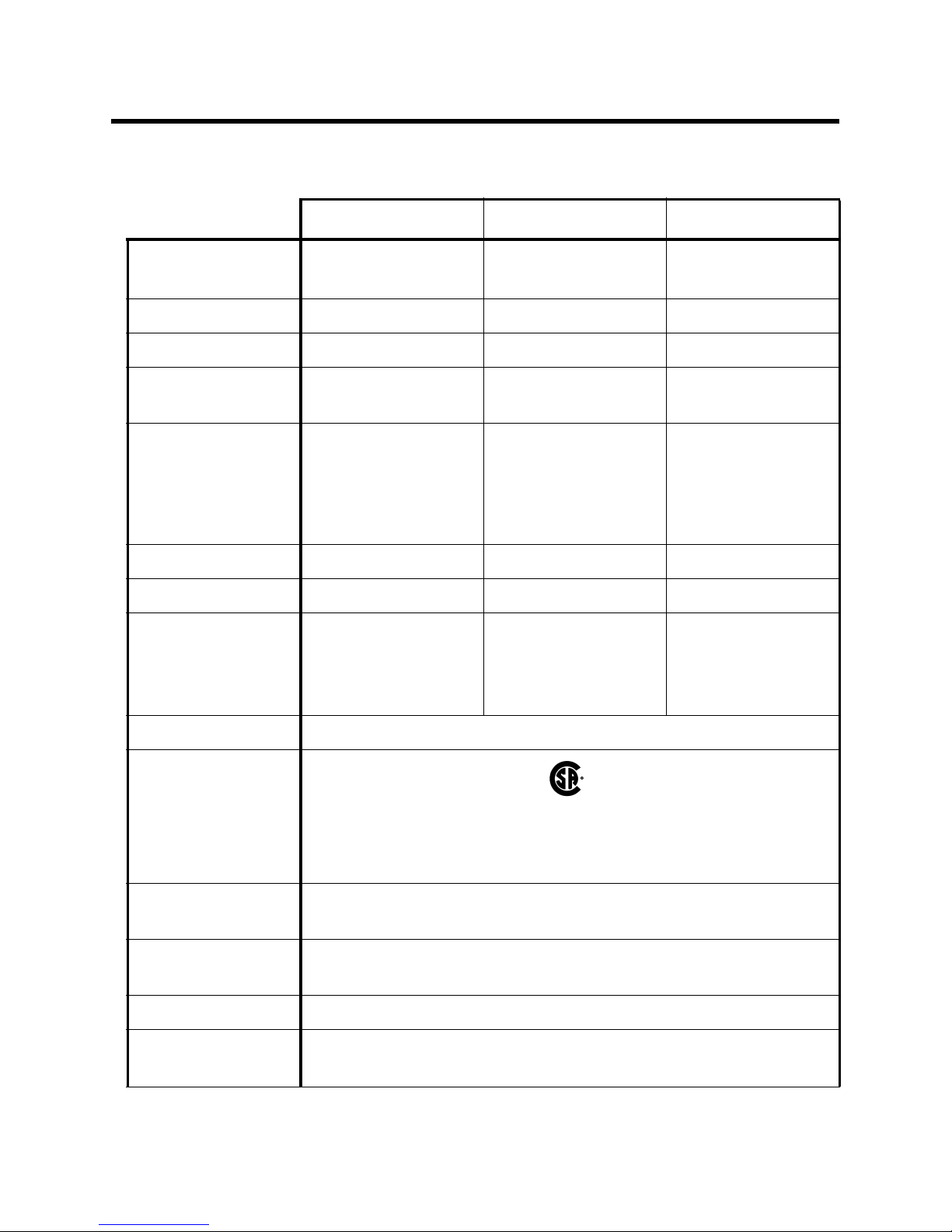
Safety/Regulatory
C US
pending
CSA classified, “C/US”, as Intrinsically Safe. Exia. Class I,
Groups A, B, C, & D. Temperature Code T3.
Power Two AAA size alkaline batteries standard, Duracell MN2400 or
PC2400, Eveready Energizer E92 or EN92
Continuous
At 25 °C: Over 3,000 hours, no alarms or backlighting
Operating Hours
Case High-impact plastic, dust and weather proof
Standard
Accessories
• Rubber protective boot
• Alligator clip
03 Series Operator’s Manual Specifications • 2
Page 8

Table 1: 03 Series Specifications
CO-03 HS-03 OX-03
Optional
Accessories
Dimensions and
Weight
Operating T emp. &
Humidity
• Calibration adapter
• Calibration kit
•Belt clip
• Wrist strap
• IrDA/USB cable for downloading data to computer
• Product CD, includes 03 Seri es Da t a logging Program and
03 Series User Setup Program
2.2” (54mm) W x 2.6” (67mm) H x 0.9” (2 4mm) D;
2.8 oz. (80 g)
-20°C to +50°C, 16 - 95% RH
(non condensing)
-20°C to +50°C,
0 - 95% RH (non
condensing)
3 • S p e c i f i c a t i o n s 03 Series Operator’s Manual
Page 9
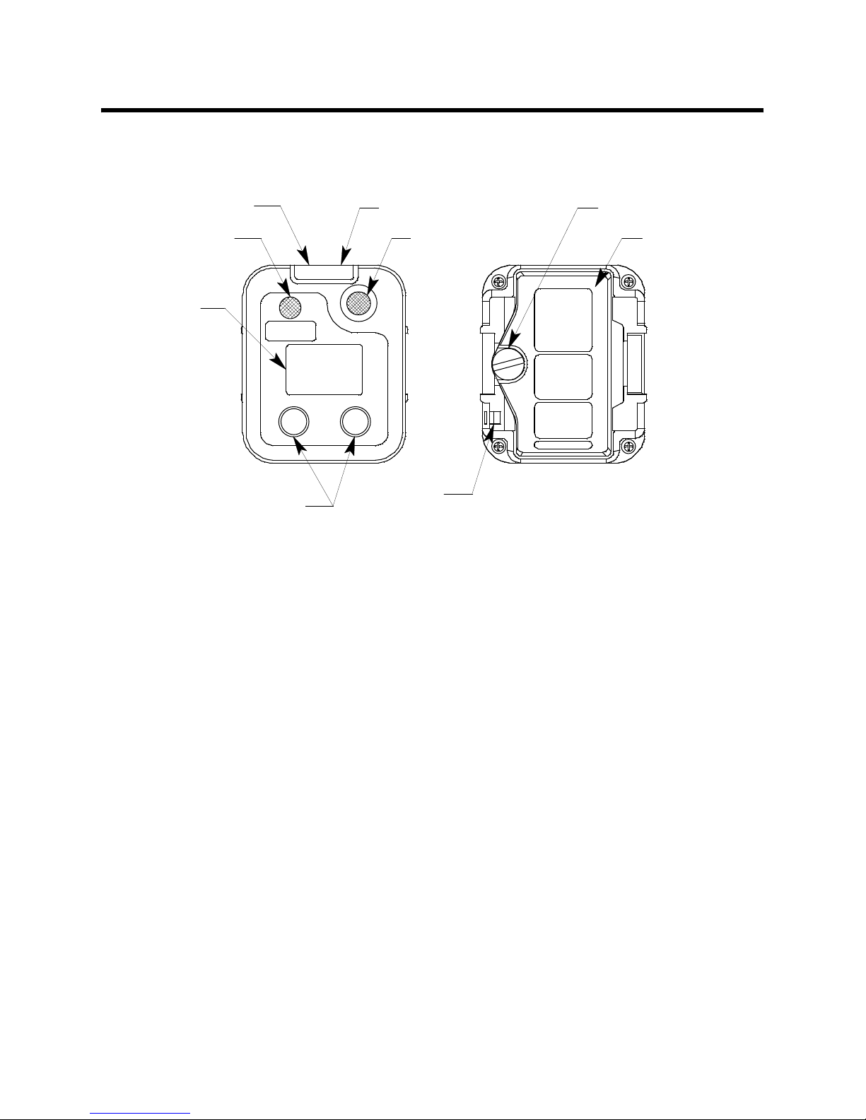
Description
w
r
This section describes the components of the 03 Series.
IrDA Port
Buzzer O pening
LCD
Control Buttons
Case
Alarm LED
Dif f usion Port
CO
CO-03
AIR
Figure 1: Components of the 03 Series
POWER
MODE
Wrist Strap
Connection
Batt ery Cover Scre
BatteryCove
The 03 Series’ sturdy, high-impact plastic case is bl ue and consists of a
front and rear cas e. The case is suitable for use in many environmental
conditions, indoors and out. The unit is dust proof and weather resistant.
The front case has an LCD (liquid crystal display) that shows various
indications. Below the LCD are two bl ack contro l butto ns. The lef t butt on is
labeled “AIR” and the right button is labeled “POWER MODE”.
The buzzer opening is located in the top lef t corner of the fron t case. To the
right of the buzzer is the diffusion port for the sensor.
The alarm LED lens is located at the top of the front case.
The battery compartment is located in the rear case. Access to the
compartment is accomplished by turning the captive battery cover screw
counterclockwise and by removing the battery cover.
There are two spri ng bars on the r ear case. On e is on t he le ft an d one i s on
the right. They are the same type of spring bar that is used to retain a
watch band and are used to mount the alligator clip or optional belt clip.
A feature in the lower left corner of the rear case is used to install the
optional wrist strap.
03 Series Operator’s Manual Description • 4
Page 10

Sensor Gasket, Sensor Membrane, and Charcoal Filter
The sensor membrane is a paper-like filter disk that is held in place by the
sensor gasket and fits into a recessed area on the inside of the front case.
The sensor membrane covers the diffusion port and protects the sensor
from dirt and moisture. The sensor membrane should be inspected
periodically and replaced if contaminated by dirt or moisture. See
“Replacing the Sensor Membrane and Charcoal Filter” on page 68 for
sensor membrane replacement instructions.
The CO-03 includes a charcoal filter disk which is located in the sensor
gasket. The charcoal filter disk removes gases from the sampled air that
will cause a response on the CO sensor such as H2S and certain
hydrocarbons. If false or elevated CO readings are noticed, especially in
the presence of H2S, change the charcoal filter disk. See “Replacing the
Sensor Membrane and Charcoal Filter” on page 68 for replacement
instructions.
Sensor
The 03 Series uses either an oxygen, CO, or H2S sensor. The sensor is
protected by the white sensor membrane which is held in place by the
sensor gasket. The sensor membrane allows ambient air to diffuse past it
to the sensor. The three sensors used in the three 03 Series models use
different detection principles as described below.
Oxygen Sensor
The oxygen sensor is a galvanic type of sensor. A membrane covers the
cell and allows gas to diffuse i nto the cell at a rate proportion al to the par tial
pressure of oxygen. The oxygen react s in the cell and prod uce s a volta ge
proportion al to the concentration of oxygen. The voltage is measured by
the 03 Series’ circuitry, converted to a measurement of gas concentration,
and displayed on the LCD.
CO and H
The CO and H
S Sensors
2
S sensors are electrochemical sensors that consist of two
2
precious metal electrodes in an acid electrolyte. A gas permeable
membrane covers the sensor face and allows gas to diffuse into the
electrolyte. The gas reacts in the sensor and produces a current
proportional to the concentration of the target gas. The current is amplified
by the 03 Series’ circuitry, converted to a measurement of gas
concentration, and displayed on the LCD.
LCD
The LCD is visible through the front case. When the 03 Series is in
Measuring Mode, the target gas concentration, battery condition, and
alarm indications are displayed on the LCD. Various other items are
5 • D e s c r i p t i o n 03 Series Operator’s Manual
Page 11

displayed when th e LCD is in other modes, such as Calibration Mode.
When either of the two control buttons are pressed, the LCD backlight
comes on for 20 seconds.
Control Buttons
Below the LCD are two control buttons: POWER MODE and AIR. The
POWER MODE button turns the 03 Series on and off. The functions
performed by the control buttons are summarized in the following table:
Table 2: 03 Series Control Buttons
Button Function
• Turns the unit on and off.
• Turns the LCD back ligh t on.
POWER MODE
• Resets the alarm circuit (gas alarms).
• Enters Display Mode.
• Enters Calibration Mode with the AIR button.
• Enters Setup Mode with the AIR button.
• Turns the LCD back ligh t on.
• Adjusts LCD reading when the fresh air
adjustment is performed.
• Enters Calibration Mode with the POWER MODE
AIR
button.
• Enters Setup Mode with the POWER MODE
button.
• Increases or decrease s settings when the unit is in
Calibration Mode or Setup Mode.
Alarm LED
The 03 Series ha s one red alar m LE D. It al ert s you to g as, low bat tery, and
sensor failure alarm s. The ala rm LED is lo cated at the top of th e fron t case
beneath a clear plastic lens.
Buzzer
A solid-state ele ctronic buzzer is mounted inside the 03 Seri es. An openin g
in the top left co rner of the fr ont case allows the buzzer’s sound to ema nate
from the case. The buzzer sounds for gas alarms, unit malfunctions, and
the dead battery alarm. It also serves as an indicator during normal use of
the various LCD display options.
Vibrator
A vibrating motor (vibrator) is mounted inside the 03 Series. The vibrator
vibrates momentarily during the power-up sequence and for gas alarms.
03 Series Operator’s Manual Description • 6
Page 12

IrDA Port
An infrared (IR) communications port is located just to the left of the alarm
LED at the top of the front case beneath the clear lens. The data
transmitted through the port is in standard IrDA protocol. A computer’s
infrared port or an IrDA/USB cable connected to a computer’s USB port
can be used to download data saved by the 03 Series to a computer using
the 03 Series Data Logger Management Program. See the 03 Series Data
Logger Manage ment Program operator’s manual for data logging and
downloading instructions.
Printed Circuit Board
The primary function of the 03 Ser ies’ pri nted circui t board is to am plify the
signal sent to it from the sensor, convert the signal to a meaningful
measurement of gas concentration, display the gas concentration on the
LCD, store STEL, TWA, and peak gas readings, and activate the alarm
circuit if an alarm poin t has been reached. It monitors battery le vel , ba tte ry
failure, and se nsor failure. It also controls various operating modes of the
unit.
NOTE: The printed circuit board contains no user serviceable parts.
Batteries
Two AAA-size alkaline batteries run the 03 Series. At 25°C the alkaline
batteries last at least 3,000 hours. The battery icon on the LCD shows
remaining batter y lif e .
When the 03 Series detects low battery voltage, a low battery warning is
activated. When battery voltage is too low for normal operation, the 03
Series sounds a dead battery alarm.
The alkaline batteries can be replaced by removing the battery cover on
the rear case. Turn the captive battery cover screw counterclockwise to
release the door. See “Replacing the Batteries” on page 64 for detailed
battery changing instructions.
WARNING: To prevent ignition of a hazardous atmosphere, batteries
must only be changed in an area known to be
nonhazardous.
7 • D e s c r i p t i o n 03 Series Operator’s Manual
Page 13
Protective Rubber Boot
A protective rubber boot is installed over the 03 Series.
Side Front
Figure 2: Rubber Boot
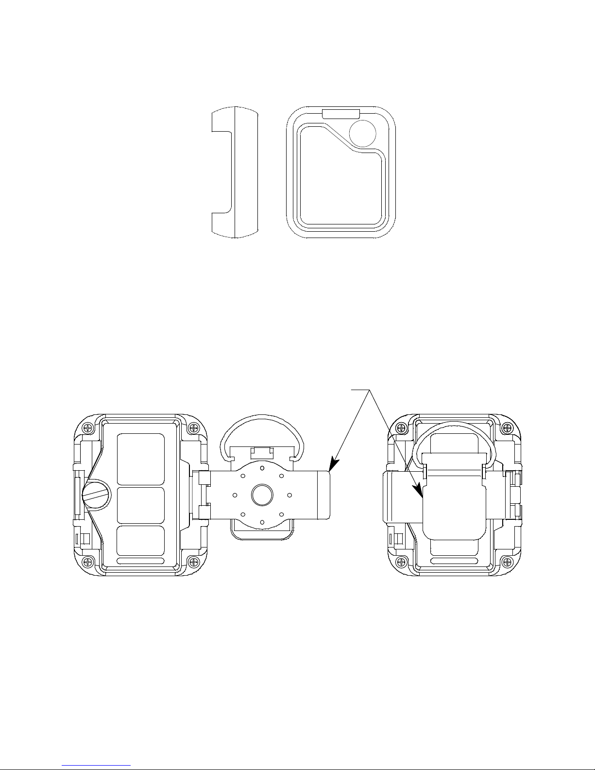
Alligator and Belt Clips
The 03 Series is available with two types of clips: the alligator clip
(standard) a nd the belt clip (opti onal). The a lligator clip is shown in Figure 3
below . The alligator cl ip can be used to a ttach the 03 S eries to clot hing or a
belt. Teeth in the clip’s jaws prevent the unit from slipping off. The clip can
be rotated in 45 degree turns if necessary.
Open
Alligator Clip
Closed
Figure 3: Alligator Clip
03 Series Operator’s Manual Description • 8
Page 14
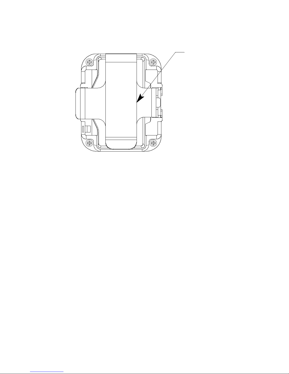
The belt clip is shown in Figure 4 below and is used to easily clip the 03
Series on a belt.
Belt Clip
Figure 4: Belt Clip
9 • D e s c r i p t i o n 03 Series Operator’s Manual
Page 15

Start Up
C.AL
This section explains how to start up the 03 Series and to get it ready for
operation.
NOTE: The screens shown in this section are for a CO-03. If you are
using a different version of the 03 Series, your instrument screen
will vary slightly from those shown below.
Start-up Procedure
1. Press and briefly hold down the POWER MODE button. The backlight
will turn on and a ll the d isplay segmen ts will turn o n. Relea se the bu tton
when you hear a beep.
2. The vibrator vibrates and the alarm light flashes momentarily.
3. The initial startup screen depends on how
This parameter al ong with the
parameters mentioned in Step 5 and the
parameter mentioned in Step 12 below cannot be set using the 03
Series’ instrument menus, but are set using the 03 Series User Setup
Program. See the 03 Seri es User Setup Progra m Operator’s Manual for
information regarding changing various instrument parameters that are
not available for adjustment in the instrument’s operating modes.
•If
Bump Fail Behavior is set to None (factory setting) or if it is set to
Can Not Use and the most recently performed bump test pas sed,
proceed to Step 5.
•If
Bump Fail Behavior is set to Can Not Use and the most recently
performed bump test failed, the following screen will appear.
FAIL
Cal. Limit Display and Cal. Limit Check
Bump Fail Behavior is set.
Auto Zero Adjustment
The instrument cannot be used until a successful bump test or
calibration is performed. See “Calibration Mode” on page 31 for
instructions.
4. If
Cal. Limit Display is set to Off, proceed to Step 6.
03 Series Operator’s Manual Start Up • 10
Page 16
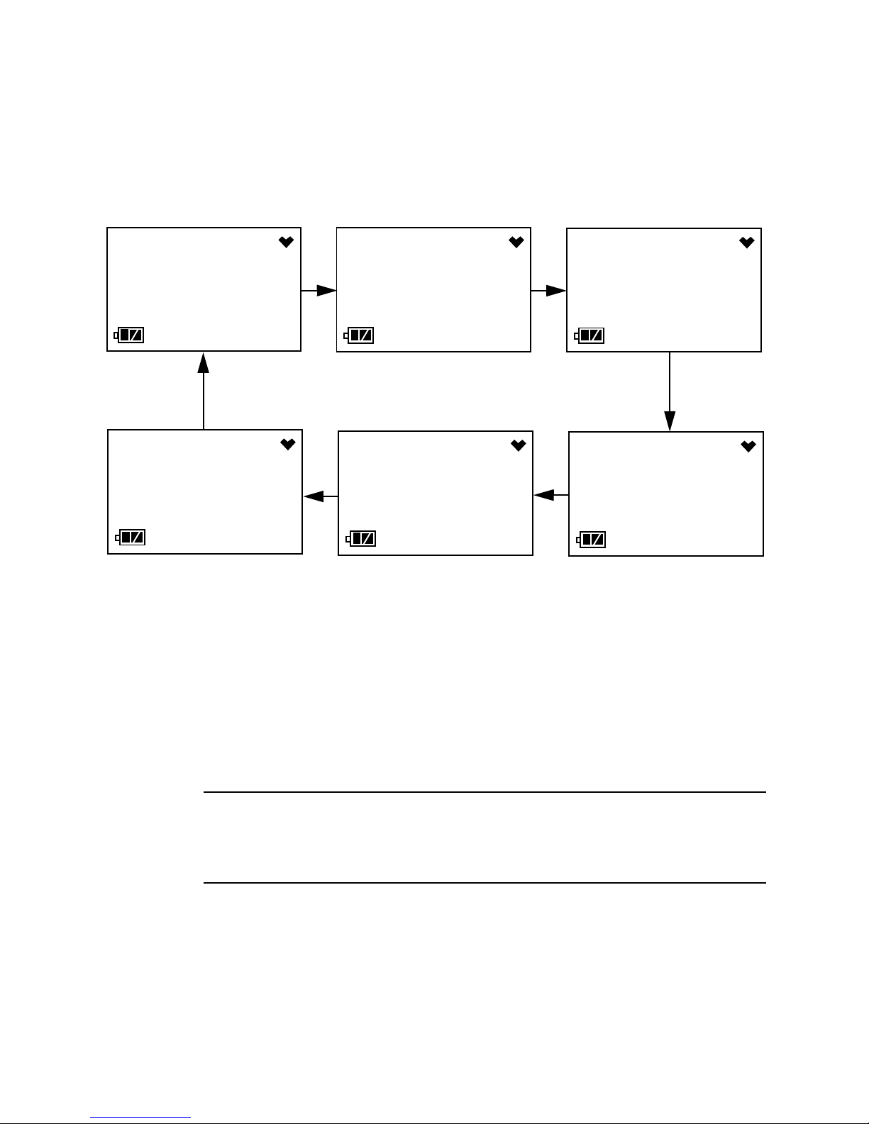
5. If Cal. Limit Display is set to On (factory setting), the screen that
C
appears next depends on how
Cal. Limit Check is set.
C.LIMIT
AL
YES
C.LIMIT
CAL
• If the unit is du e for calibration and
Confirm to use (factory setting), then the follow ing scre en sequ ence
will occur.
C.LIMIT
CAL
MODE
Cal. Limit Check is set to
C.LIMIT
CAL
C.LIMIT
CAL
AIR
C.LIMIT
CAL
NO
The alarm LED and buzzer will pulse several times.
To continue the startup sequence without performing a calibration,
press and release the AIR button. Continue to Step 6.
To perform a calibration, press and release the POWER MODE
button. Depending on the valu e ente r ed in to the
Time parameter using the 03 Series User Setup Program, the
instrument will displa y either the A--CAL menu item or the E--CAL
menu item in Calibration Mode. See “Calibration Mode” on page 31
for instructions.
WARNING: You must press either the POWER MODE or AIR button to
continue. If you do not press a button, the buzzer will
continue to beep and the LED will continue to flash for 6
seconds every 5 seconds.
One Touch Cal
11 • S t a r t U p 03 Series Operator’s Manual
Page 17
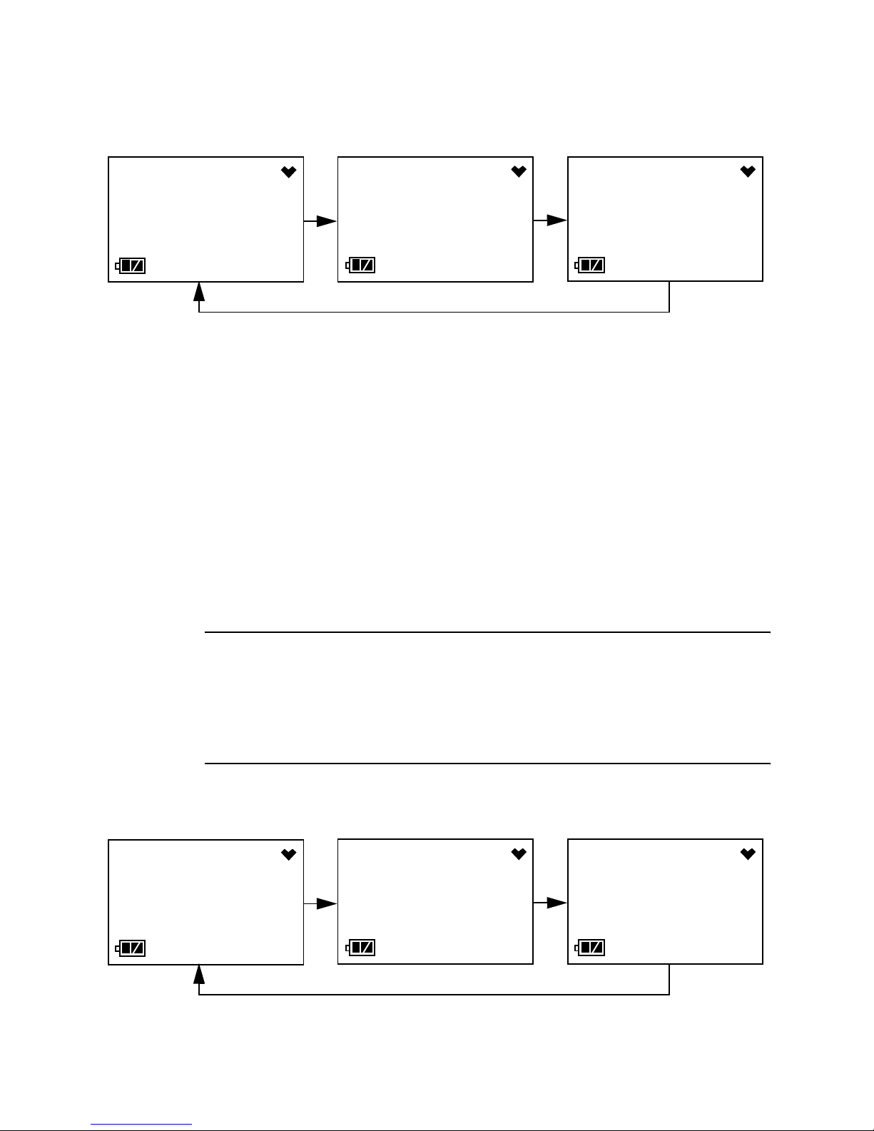
• If the unit is du e for calibration and Cal. Limit Check is set to Can’t
use, then the following screen sequence will occur.
C.LIMIT
FAIL
YES
C.LIMIT
FAIL
MODE
C.LIMIT
FAIL
The alarm LED and buzzer will pulse several times. Press and
release the POWER M ODE button . Depending on the value en tered
into the
Setup Program, the instrument will display either the A--CAL menu
item or the E--CAL menu item in Calibration Mode. The above
screen will remain on the display until the unit is either tu rned off or
Calibration Mode is entered. The 03 Series cannot be used until a
complete calibration has been performed either by selecting A-CAL, E--CAL, or M--CAL in the Calibration Mode menu. See
“Performing an Automatic Span Adjustment (Zero Adjustment for
OX-03) in A--CAL” on page 34, “Performing an Easy Span
Adjustment (Zero Adjustment for OX-03) in E--CAL” on page 39, or
“Performing a Manual Span Adjustment (Zero Adjustment for OX-
03) in M--CAL” on page 45 for cal i bration instructions.
One Touch Cal Time parameter using the 03 Series User
C.LIMIT
YES
WARNING: You must perform a successful calibration in order to
continue to normal operation. If you do not perform a
successful calibration, the screen sequence will
continue, the buzzer will continue to beep, and the LED
will continue to flash for 6 seconds every 5 seconds and
the unit will not enter normal operation.
• If a calibration is due and Cal. Limit Check is set to None, the
sequence below will occur twice.
C.LIMIT
0d 0d
MODE
C.LIMIT
0d
03 Series Operator’s Manual Start Up • 12
Page 18

Press and release the POWER MODE button during this time to go
t
t
to the A--CAL or E--CAL menu item in Calibration Mode depending
on the value entered into the
03 Series User Setup Program. If no button is pressed, the
instrument will continue with the warmup sequence in Step 6 once
the sequence shown above has finished.
• If calibration is not due, then the following screen appears for a few
seconds indicating when the next calibration is due. “NEXT” and
“CAL” alternate on the bottom of the screen.
One Touch Cal Time parameter of the
14. 2.17
180d
NOTE: The following screens in Step 6 only appear if Bump Test Limit
6. If
7. If
CAL.
Display is set to On using the 03 Series User Setup Program. The
standard factory setting for this function is Off.
Bump Test Limit Display is set to Off (factory setting), proceed to
Step 8.
Bump T est Limit Display is set to On using the 03 Series User Setup
Program, the next screen will depend on how
is set in Setup Mode or using the 03 Series User Setup Program.
• If the unit is due fo r bump test ing an d
to
Confirm to use (factory setting), then the following screen
sequence will occur.
14. 2.17
180d
NEXT
Bump Test Limit Check
Bump T est Limit C heck is set
NOW
eSt
BUMP
eSt
13 • S t a r t U p 03 Series Operator’s Manual
YES
BUMP
teSt
MODE
NOW
teSt
AIR
NOW
teSt
BUMP
teSt
NO
Page 19
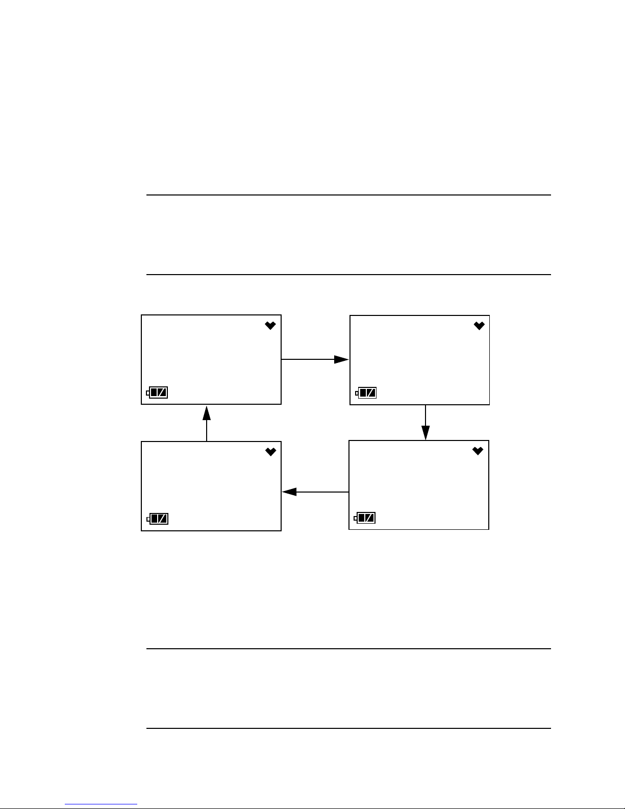
The alarm LED and buzzer will pulse several times.
To continue the startup sequence without performing a bump test,
press and release the AIR button. Continue to Step 8.
To perform a bump test, press and release the POWER MODE
button. The instrument will display the BUMP menu item in
Calibration Mode. See “Performing a Bump Test in BUMP” on
page 48 for instructions.
WARNING:You must press either the POWER MODE or AIR button to
continue. If you do not press a button, the screen
sequence will continue, the buzzer will continue to beep
and the LED will continue to flash for 6 seconds every 5
seconds.
• If the unit is due fo r bump test ing an d Bump T est Limit Check is set
to
Can’t use, then the following screen sequence will occur.
NOW
FAIL
YES
BUMP
FAIL
The alarm LED and buzzer will pulse several times. Press and
release the POWER MOD E but ton to go to the BUMP menu item in
Calibration Mode. The above screens will remain on the display until
the unit is either turned off or Calibration Mode is entered. The 03
Series cannot be used until a bump test has been performed. See
“Performing a Bump Test in BUMP” on page 48 for bump test
instructions.
BUMP
FAIL
MODE
NOW
FAIL
WARNING:You must perform a successful bump test in order to
03 Series Operator’s Manual Start Up • 14
continue to normal operation. If you do not perform a
successful bump test, the buzzer will continue to beep and
the LED will continue to flash for 6 seconds every 5
seconds and the unit will not enter normal operation.
Page 20
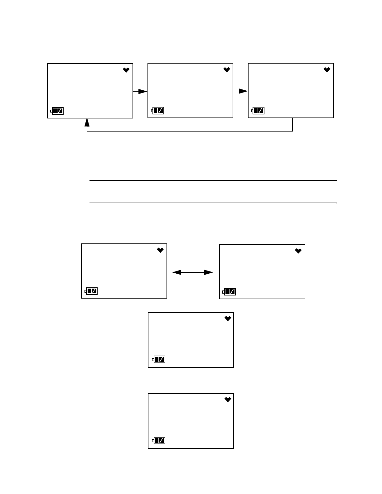
• If a bump test is due and Bump Test Limit Check is set to None,
2014
bAtt
the sequence below will occur twice.
BUMP
YES
BUMP
0d 0d
MODE
BUMP
0d
Press and release the POWER MODE button during this time to go
to the BUMP menu item in Calibration Mode. If no button is pressed,
the instrument will continue with the warmup sequence in Step 8
once the sequ ence shown above has finished.
NOTE: If a successful calibration is performed, the next bump test date is
reset and starts over even though a bump test w as n ot p erfo rmed .
• If bump testing is not due, then the following screen appears for a
few seconds indicatin g when the next bump test is du e. “NE XT” and
“BUMP” alternate on the bottom of the scr een.
14. 2.17
180d
BUMP
14. 2.17
180d
NEXT
8. The Date/Time Screen appears for a few seconds.
This screen displays the current date and time.
9. The Battery Voltage Screen appears for a few seconds.
15 • S t a r t U p 03 Series Operator’s Manual
1.31
8:20
3.0
V
Page 21
The screen displays the current battery voltage.
SENSOR
F
AUTO
-
CAUTION: If the unit gives a low battery warning or dead battery alarm,
change the alkaline batteries before using the unit.
10.The display then indicates the following items for about a second each:
• Full scale value
• Warning setpoint (low gas alarm)
• Alarm setpoint (hi gh ga s alar m )
• STEL alarm setpoint (CO and H2S only)
• TWA alarm setpoint (CO and H2S only)
11. If the 03 Series experiences a sensor failure during start up, the
following screen will appear.
The instrument cannot be used if a sensor failure occurs. Replace the
failed sensor.
12.If
Auto Zero Adjustment is set to On (factory setting is Off), then the
03 Series will perform an au tom at ic fresh ai r adju stm en t.
- - -
If the fresh air adjustment is successful, the unit will proceed to Normal
Mode. If the sensor fails the air adjustment, the screen will indicate the
failure. If a failur e occur s, pre ss and r elease th e P OWER MO DE bu tton
to proceed to Normal Mode. Replace the failed sensor as soon as
possible.
AIL
ZERO
03 Series Operator’s Manual Start Up • 16
Page 22
WARNING: If the Auto Zero Adjustment feature is turned on, make
CO
AIR
sure that you start-up the 03 Series in a known fresh air
environment, an environment free of combustible or toxic
gasses and of normal oxygen content, 20.9%. If you do
not start-up the unit in a fresh air environment, the fresh
air adjustment will not be accurate.
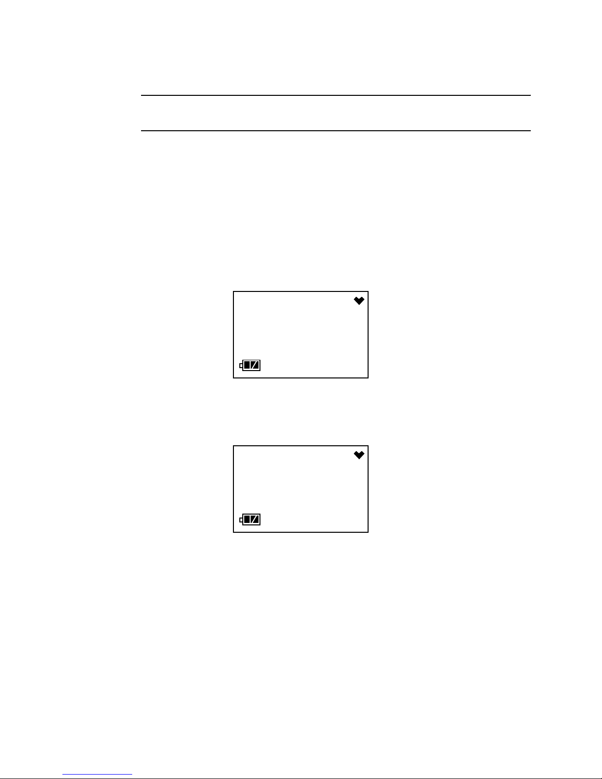
13.The 03 Series is now operating in Measuring Mode and monitoring for
gas. The Normal Opera ti on Scre en app ea rs an d the in str um en t beeps
once.
The gas concentration of the target gas is displayed along with the
battery charge level in th e lower l eft co rner. The heart symbol displaye d
in the upper right corner flashes while the instrument is functioning
properly. If it disappears or is steadily on, the unit is experiencing a
microprocessor error. The backlight turns off after 20 seconds.
Performing a Fresh Air Adjustment
Before using the 03 Series, set the fresh air reading. Performing this
adjustment ensures accurate gas readings in the monitoring environment.
1. Find a fresh air environment of normal oxygen content (20.9%) that is
free of toxic or combustible gases.
2. With the unit on and in Measuring Mo de, press and hol d the AIR button.
The LCD displays “hold” prompting you to hold the AIR button.
ppm
0
17 • S t a r t U p 03 Series Operator’s Manual
- - - -
HOLD
Page 23

3. Release the AIR button when the following screen appears. The unit
ADJ
will set the reading t o 0 ppm (20.9% for the OX-03) and return to
Measuring Mode.
- - - -
Turning Off the 03 Series
1. Press and hold the POWER MODE button for about five seconds to
turn off the unit. The buzzer will pulse while the POWER MODE button
is being pressed before the unit turns off.
2. Release the button when the LCD is blank. The unit is off.
NOTE: If Power Off Password Protection is turned On (factory setting is
Off) using the 03 Series User Setup Program, a password is
required to turn the 03 Series off. When the password screen
appears, adjust each digit with the AIR button and press and
release the POWER MODE button to move on to the next digit.
Once the password has been entered, the instrument will shut off
and the LCD will be blank.
03 Series Operator’s Manual Start Up • 18
Page 24

Operation
CO
This section describes Measuring Mode, setting the buzzer volume,
Display Mode, and alarm indications.
NOTE: The screens shown in this section are for a CO-03. If you are
using a different version of the 03 Series, your instrument screen
will vary slightly from those shown below.
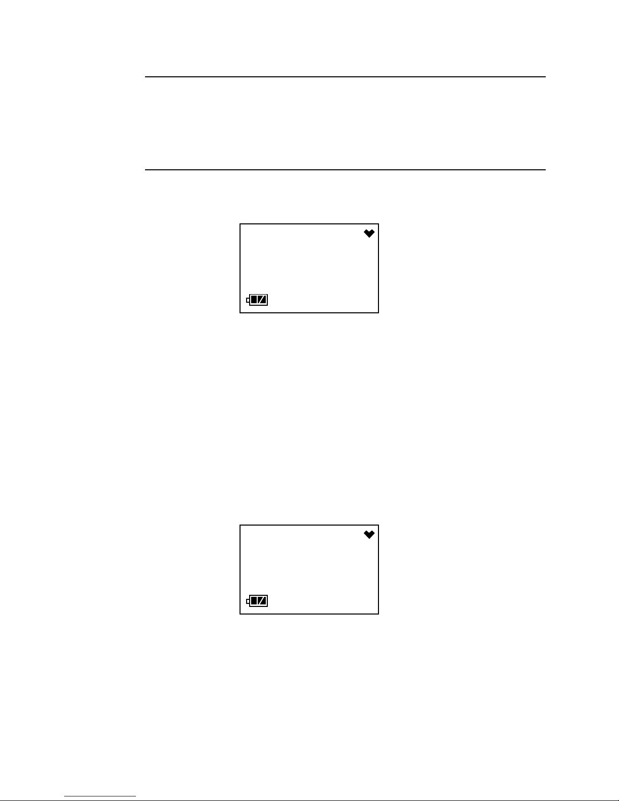
Measuring Mode
In Measuring Mode, the battery level and target gas concentration are
displayed on the LCD. The battery icon has three bars visible when the
batteries have a full charge. As the battery charge decreases, the bars will
gradually disappear, one by one. The heart symbol displayed in the upper
right corner flashes while the instrument is functioning properly. If it
disappears or is steadily on, the unit is experiencing a microprocessor
error.
The target gas conce ntrat ion is displayed in the middle of the LCD. On the
CO-03, CO is displayed in parts per million (ppm). On the HS-03, H
displayed in ppm. On the OX-03, oxygen is displayed as volume percent.
ppm
0
S is
2
Adjusting the Buzzer Volume
The buzzer volume on the 03 Series can be adjusted while in Measuring
Mode if
Buzzer Volume Selection setting can be adjusted using the 03 Series
User Setup Program. The default buzzer volume setting is HI. If it is
changed to LO, the setting will revert back to HI the next time the
instrument is turned on.
1. Make sure the 03 Series is in the Measuring Mode Normal Operation
2. Press and hold the POWER MODE and AIR buttons simultaneously.
Buzzer Volume Selection is set to On (factory setting is Off). The
screen.
NOTE: To avoid entering Display Mode, press the AIR button slightly
sooner than pressing the POWER MODE button.
Release both buttons when the instrument starts simulating an alarm
19 • Operation 03 Series Operator’s Manual
Page 25

condition after the second beep. The current setting for the buzzer will
b
CO
be displayed and the current volume will be emanating from the buzzer .
3. Use the AIR button to select LO or HI. The buzzer volume during the
simulated alarm condition will change as you select a different volume.
4. Press and release the POWER MODE button to save the setting and
return to Normal Operation.
5. If LO was selected, “B--LO“ will appear at the bottom of the Normal
Operation screen .
- HI
BEEP
B--LO
ppm
0
Display Mode, CO-03 and HS-03
This section describes Display Mode for CO-03 and HS-03 instruments
only. See “Display Mode, OX-03” on page 22 for a description of the OX03’s Display Mode.
You can access Display Mode while in Measuring Mode by using the
POWER MODE button. In Display Mode you can view and reset the peak
readings, view the TWA and STE L values, view the detection range full
scale, and view the date and time.
STEL is an acronym for short-term exposure limit, and it is the average
reading of the target gas during the last 15 minutes. TWA is an acronym for
time-weighted average, and it is the average reading for the target gas
during the last eight (8) hours. If eight (8) hours has not elapsed since the
unit was turned on, the TWA is still calculated over eight hours, with the
missing time assigned a zero (0) value for the readings. Similarly , if the unit
has not been on for 15 minutes, the missing time is assigned a 0 value and
the STEL is calculated over 15 minutes. The peak readings, STEL values,
and TWA values are cleared when the unit is turned off.
To enter Display Mode, do the following:
1. Make sure the 03 Series is in the Measuring Mode Normal Operation
screen. The 03 Series must be i n the Norm al Operation Screen for you
to access Display Mode.
03 Series Operator’s Manual Operation • 2 0
Page 26

2. Press and release the POWER MODE button to enter Display Mode.
PEAK
CLEAR
-
CLEAR
-
STEL
The backlight will turn on and the PEAK Screen will appear.
The peak reading since the 03 Series was turned on is displayed.
3. If you do not want to clear the peak reading, continue to the next step.
If you want to clear the peak reading, press and hold the AIR button.
After a couple of seconds, the LCD will prompt you to hold the AIR
button with the following screen.
- - -
Hold the AIR button until the following screen appears, then release it.
- - -
15
HOLD
ppm
The peak reading will be cleared and the unit will return to the PEAK
Screen.
4. Press and release the POWER MODE button again to proceed to the
STEL Screen. The STEL reading will be displayed.
21 • Operation 03 Series Operator’s Manual
5
ppm
Page 27

5. Press and release the POWER MODE button again to proceed to the
TWA
F. S.
2014
TWA Screen. The TWA reading will be displa yed.
6. Press and release the POWER MODE button again to proceed to the
Full Scale Screen. Th e detect io n range fu ll scal e value i s displaye d. An
“L” or an “A” will appear under the full scale value to indicate whether
the alarms are set to latching (L) or auto-resetting (A). This setting can
be adjusted using the 03 Series User Setup Program.
7. Press and release the POWER MODE button again to proceed to the
Date/Time Screen. The date and time of the instrument is displayed.
1.31
500
8:20
10
L
ppm
ppm
8. Press and release the POWER MODE button once again to return the
unit to Measurin g Mode.
NOTE: If you do not press a button for 20 seconds while in Display Mode,
the unit will return to Measuring Mode automatically and the
backlight will tu rn off.
Display Mode, OX-03
This section describes Display Mode for the OX-03 only. See “Display
Mode, CO-03 and HS-03” on page 20 for a description of the CO-03 and
HS-03 instruments’ Display Mode.
You can access Display Mode while in Measuring Mode by using the
POWER MODE button. In Display Mode you can view and reset the
minimum and maximum readings, view the detection range full scale, and
03 Series Operator’s Manual Operation • 2 2
view the date and time.
Page 28

To enter Display Mode and view items or reset the peak readings, do the
MIN.
CLEAR
-
CLEAR
-
following:
1. Make sure the 03 Series is in the Measuring Mode Normal Operation
screen. The 03 Series must be i n the Norm al Operation Screen for you
to access Display Mode.
2. Press and release the POWER MODE button to enter Display Mode.
The backlight will turn on.
3. The Min. Screen will be displayed. This is the minimum oxygen reading
taken since the instrument was turned on.
4. If you do not want to clear the minimum reading, continue to the next
step.
If you want to clear the minimum reading, press and hold the AIR
button. After a couple of seconds, the LCD will prompt you to hold the
AIR button with the following screen.
- - -
Hold the AIR button until the following screen appears, then release it.
- - -
20.1
HOLD
%
The minimum readi ng w il l be cle ared and the unit will return to the Min.
Screen.
23 • Operation 03 Series Operator’s Manual
Page 29

5. Press and release the POWER MODE button to display the Max.
MAX.
CLEAR
-
CLEAR
-
F. S.
Screen. This is the maximum oxygen reading taken since the
instrument was turned on.
6. If you do not want to clear the maximum reading, continue to the next
step.
If you want to clear the maximum reading, press and hold the AIR
button. After a couple of seconds, the LCD will prompt you to hold the
AIR button with the following screen.
- - -
Hold the AIR button until the following screen appears, then release it.
- - -
21.2
HOLD
%
The maximum reading will be cleared and the uni t will return to the Max.
Screen.
7. Press and release the POWER MODE button again to proceed to the
Full Scale Screen. Th e detect io n range fu ll scal e value i s displaye d. An
“L” or an “A” will appear under the full scale value to indicate whether
the alarms are set to latching (L) or auto-resetting (A). This setting can
be adjusted using the 03 Series User Setup Program.
03 Series Operator’s Manual Operation • 2 4
40.0
L
%
Page 30

8. Press and release the POWER MODE button again to proceed to the
2014
Date/Time Screen. The date and time of the instrument is displayed.
1.31
9. Press and release the POWER MODE button once again to return the
unit to Measurin g Mode.
NOTE: If you do not press a button for 20 seconds while in Display Mode,
the unit will return to Measuring Mode automatically and the
backlight will tu rn off.
8:20
Alarms
This section covers alarm indications. It also tells you how to reset the 03
Series after an alarm has occurred and how to respond to an alarm
condition.
Alarm Indications
The 03 Series will sound the buzzer, flash its alarm LED, and vibrate when
the target gas concentration rises above (falls below for oxygen) the
warning level. The 03 Series also sounds the buzzer, flashes its alarm
LED, and vibrates when the alarm level is reached. In addition, the 03
Series has a low battery warning, a dead battery alarm, an over range
alarm, a sensor failure alarm, a system failure alarm, and a clock failure
alarm. See Table 3 below for a description of each alarm indication.
Alarm Type Visual Indications Other Indications
Warning
Concentration of gas
rises above (fall s
below for OX-03) the
warning level.
25 • Operation 03 Series Operator’s Manual
Table 3: Alarm Types and Indications
• Gas reading
flashes.
•
WARN appears
below the gas
reading.
• Back light turns on.
• Alarm LED flashes.
• Buzzer sounds
alternating between
a low and high
pitch.
• Vibrator pulses.
Page 31

Table 3: Alarm Types and Indications
Alarm Type Visual Indications Other Indications
Alarm
Concentration of gas
rises above the alarm
level.
TWA or STEL
(CO-03 & HS-03 Only)
Concentration of CO
or H
S rises above the
2
TWA or STEL alarm
point.
• Gas reading
flashes.
•
ALRM appears
below the gas
reading.
• Back light turns on.
• Alarm LED flashes
faster than warning
indication.
• Back light turns on.
• Gas reading
flashes.
•
TWA or STEL
appears below the
gas reading.
• If the unit is in both
TWA alarm and
STEL alarm, only
STEL will be
displayed.
• Alarm LED flashes.
• Buzzer sounds
alternating between
low and high pitch
faster than warning
indication.
• Vibrator pulses
faster than warning
indication.
• Buzzer sounds
alternating between
a low and high pitch
at same rate as
warning indication.
• Vibrator pulses at
same rate as
warning indication.
Over Range
Concentration of gas
rises above the
• Gas reading
replaced by blinking
brackets.
measuring limit of the
03 Series. (Or there
could be a problem
with the unit.)
• Back light turns on.
•
ALRM appears
below gas reading .
Low Battery Warning • Last remaining bar
on the right in
battery icon
flashes.
Dead Battery Alarm • Gas reading
replaced by
FAIL.
• Battery icon
flashes.
• Buzzer sounds
alternating between
low and high pitch
at the same rate as
alarm indication.
• Vibrator pulses at
same rate as alarm
indication.
•None
• Double pulsing to ne
(two pulses in quick
succession) occurs
once a second.
03 Series Operator’s Manual Operation • 2 6
Page 32

Table 3: Alarm Types and Indications
Alarm Type Visual Indications Other Indications
Sensor Failure • Gas na me replaced
SENSOR.
by
• Gas reading
replaced by
FAIL.
• Double pulsing to ne
(two pulses in quick
succession) once a
second.
• Alarm LED flashes.
System Failure • Gas name repl aced
SYSTEM.
by
• Gas reading
replaced by
FAIL.
• Double pulsing to ne
(two pulses in quick
succession) once a
second.
• Failure code
displays below
FAIL.
Clock Failure • Gas name repl aced
FAIL.
by
• Gas reading
replaced by
FAIL.
• Double pulsing to ne
(two pulses in quick
succession) once a
second.
Resetting Gas Alarms
If the alarms are latching (factory setting), then an alarm indication will
continue even if the gas reading causing the alarm decreases below the
alarm setpoint (increases a bove for o xygen W arnin g) and will continue until
the alarm is reset. The gas reading that caused the alarm must decrease
below the alarm setpoint (increase above for oxygen Warning) before that
alarm can be reset. To reset latching alarms, press and release the
POWER MODE button after the gas reading falls below the alarm setpoint
(rises above for oxygen Warning).
If the alarms are self-resetting, then an alarm condition will automati cally
reset when the gas reading that caused the alarm decreases below the
alarm setpoint (increases above for oxygen Warning).
Responding to Alarms
This section describes response to gas, over range, battery, sensor failure,
and system failure alarms.
Responding to Gas Alarms
1. Follow your established procedure for an increasing gas conditi on or a
decreasing oxygen condition.
2. If your unit is set for latching alarms, reset the alarm using the POWER
MODE button once the alarm condition has been cleared.
27 • Operation 03 Series Operator’s Manual
Page 33

Responding to an Over Range Alarm
WARNING: An over range condition may indicate an extreme toxic
gas or oxygen concentration. Confirm the gas
concentration with a different 03 Series or with another
gas detecting device.
1. Follow your established procedure for an increasing gas conditi on.
2. Reset the alarm by pressing and releasing the POWER MODE button
after the alarm condition has cleared.
3. Calibrate the 03 Series as described in “ Calibration Mode” on page 31.
4. If the over range condition continues, replace the sensor as described
in “Replacing the Sensor” on page 66.
5. If the over range condition continues after you have replaced the
sensor, contact RKI Instruments, Inc. for further instructions.
Responding to Battery Alarms
WARNING: The 03 Series is not operational as a gas monitoring
device during a dead battery alarm. Take the 03 Series to
a non-hazardous area and change the alkaline batteries
as described in “Replacing the Batteries” on page 64.
The 03 Series is fully functional in a low battery warning condition.
However, only a couple of days of operation may remain depending on
certain conditions such as alarm occurrences an d how often the backlight
comes on.
NOTE: Alarms and the back light feature consume battery power and
reduce the amount of operating time remaining.
When a low battery warning occurs, change the batteries as soon as
possible. Refer to the instructions in “Replacing the Batteries” on page 64
for more information.
Responding to a Sensor Failure Alarm
1. Try calibrating the 03 Series as described in “Calibration Mode” on
page 31.
2. If the sensor failure continues, replace the sensor as described in
“Replacing the Sensor” on page 66.
3. If the gas sensor fa ilure co nditio n contin ues af ter you have re placed the
gas sensor, contact RKI Instruments, Inc. for further instructions.
03 Series Operator’s Manual Operation • 2 8
Page 34

Responding to a System Failure Alarm
SYSTEM
1. If a system failure occurs, the system failure screen will display an error
code as shown below:
2. The error cod e meanings are shown below:
Table 4: Error Code Explanation
Error Code Explanation
000 MPU failure
010 RAM failure
021 EEPROM failure
3. The instrument cannot be used if a system failure occurs. Contact RKI
Instruments, Inc. as soon as possible.
Responding to a Clock Failure Alarm
This alarm occurs if the internal unit date has been changed to something
unreasonable like 15/34 (month/day).
FAIL
021
1. Press and release the POWER MODE button to continue into normal
operation.
CAUTION: There will be no dataloggin g function if you operate the
instrument after a clock failure.
2. Attempt to change the date using the DATE menu item in Calibration
Mode. See “Setti ng the Date and Time” on page 3 3.
3. If the date cannot be set correctly, contact RKI Instruments, Inc. as
soon as possible.
29 • Operation 03 Series Operator’s Manual
Page 35

Data Logging
The 03 Series features the ability to log data to its internal memory and
download it to a computer via the IrDA port on the top of the case. It logs
normal operation gas readings, alarm data, calibration data, and bump test
data.
To utilize the 03 Series’ downloadin g capab ility, you will need the 03 Series
Data Logger Management Program and a computer with an infrared port
that conforms to IrDA 1.1 protocol or a USB port that runs one of the
following operating systems: Windows XP, Windows Vista, Windows 7 or
Windows 8. If your co mpute r ha s an infr ared p ort th at conf orms to IrDA 1.1
protocol, then no addition al accessories a re need ed to down load dat a from
the 03 Series. If your computer does not have an infrared port but does
have a USB port, a U SB/Ir DA a dapte r cable can be used to down loa d dat a
from the 03 Series using the USB port. The 03 Series Data Logger
Management Program is included in the produc t CD and is also available
from RKI Instruments, Inc. The adapter cable is also available from RKI.
See the 03 Ser ies Data Logger Management Program Operator’s Manual
for a complete description of the 03 Series Data Logger Management
Program and procedure s for downloading data to a computer.
03 Series User Setup Program
There are some instrume nt operating p arameter s that are not accessi ble in
either Calibration Mode or Setup Mode su ch as the calibration frequency,
auto zero function, and the alarm logic (latching or self resetting). Many of
these parameters either do not typically need to be accessed once the 03
Series is shipped from the factory or may only need to be accessed once
because of operator preference s. These pa ramete rs can be accessed and
updated if necessa ry usin g the 03 Seri es Us er S etup Prog ram, a co mpute r
with the same requirements described above in “Data Logging”, and a
USB/IrDA cable if necessary. The 03 Series User Setup Program is
included in the product CD and is a lso availa ble from RKI Instr ument s, Inc.
The adapter cable is also available from RKI. See the 03 Series User
Setup Program Operator’s Manual for a complete description of the 03
Series User Setup Program and procedures for accessing and updating
instrument operating parameters.
03 Series Operator’s Manual Data Logging • 3 0
Page 36

Calibration Mode
This section desc r ibes the 03 Series in Calibration Mode. In Calibration
Mode, you can move through a menu of screens to do the following:
• Set the date and time
• Perform a fresh air adjustment (part of a calibration)
• Perform an automatic span adjustment (part of a calibration)
• Perform an easy span adjustment (part of a calibration)
• Perform a manual span adjustment (part of a calibration)
• Perform a bump test (if
03 Series User Setup Program)
• View the instrument’s firmware version and firmware checksum
NOTE: You can set the 03 Series to alert you during the star tup sequence
when calibration or bump testing is due with the 03 Series User
Setup Progra m. See the 03 Series User Set up Program
Operator’s Manual for information on setting the
Display and Bump Test Limit Display parameters.
Bump Test Function is set to On using the
Cal. Limit
Calibration Frequency
The optimum frequency of calibration depends heavily on how the 03
Series is used. For example, instruments used daily may need to be
calibrated weekly or monthly, while instru ments that are used only a few
times a year may need to be calib rated before ea ch use. T ypica l calibration
frequencies range from monthly to quarterly. Make sure to develop a
calibration schedule tailored to your application.
Using Calibration Mode
WARNING: The 03 Series is not in operation as a gas detector while
1. Take the 03 Series to a non-hazardous area and turn it off if it is on.
31 • C a li b r a t i o n M o d e 03 Series Operator’s Manual
in Calibration Mode. Although it will respond to gas in
parts of AIR CAL, A--CAL., M--CAL., and BUMP, there are
no gas alarm indications.
Page 37

2. Press and hold the AIR button, then press and hold the POWER MODE
DATE
START
button. When you hear a beep release the butto ns. The DA TE Screen is
displayed.
3. Use the AIR button to move forward through Calibration Mode. When
you get to the last menu item, the START menu item, continuing will
take you back to the beginning of the menu.
4. When you arrive at the item you wish to enter, press and release the
POWER MODE button to enter that item.
5. When you need to adju st the numerical valu e of a param eter , increase it
or decrease it, use the AIR b utt on t o ch an ge the value. When adjusting
a numerical parameter value, it is possible to reverse the direction of
adjustment. To switch from increasing to decreasing a value or
decreasing to increasing a value, do the following:
• with the parameter flashing on the screen, press and hold the AIR
button
• immediately press the POWE R MODE button a nd then release both
buttons
• the direction of adjustment when you press the AIR button is now
reversed
6. When you are done using the menu items in Calibration Mode, use the
AIR button to scroll through the menu items to the START item.
7. At the START screen, press and release the POWER MODE button.
The 03 Series will begin its start-up sequence.
The Calibration Mode menu items are described below in the order in
which they appear while moving through Calibration Mode.
03 Series Oper ator’s Manual Calibration Mode • 3 2
Page 38

Setting the Date and Time
DATE
2014
AIR
Entering the DATE menu item allows you to set the date and time.
1. When the DATE Screen is displayed, press and release the POWER
MODE button. A screen ap pears with the year flashing in the uppe r lef t,
the month and day in the middle, and the time in the lower right.
2. Use the AIR button to display the desire d year.
3. Press and release the POWER MODE button to save the setting. The
month setting flashe s.
4. Repeat steps 2 and 3 to enter the month, day, hour and minute setting.
When you save the minute setting, END is displayed before the
instrument returns to the DATE Screen.
2.11
3:05
Performing a Fresh Air Adjustment
Entering the AIR menu item allows you to perform a fresh air adjustment.
Perform a fresh air adjustment in Calibration Mode when you are
performing a calibr ati on bef or e pr oce ed ing ei th er to th e A- - CAL or M- - CAL
menu item to perform a span adjustment (zero adjustment for OX-03). A
fresh air adjustment performed in Calibration Mode is the same as a fresh
air adjustment in Normal Mode. The AIR menu item is available in
Calibration Mode for convenience when performing a complete calibration.
WARNING: Calibrate the 03 Series in a non-hazardous environment.
33 • C a li b r a t i o n M o d e 03 Series Operator’s Manual
Page 39

1. Find a fresh air environmen t, an envir onment o f normal oxyg en conte nt
AIR
AIR
ADJ
(20.9%) that is free of toxic and combustible gasses.
2. When the AIR screen is displayed, press and release the POWER
MODE button. A screen appears that displays the current gas reading.
If you want to cancel the fresh air adjustment, press and release the
AIR button to return to the AIR screen. To continue with the fresh air
adjustment, proceed to Step 3.
3. Press and hold the AIR button. The LCD prompts you to continue to
hold the AIR button.
- - - -
4. Release the AIR button when the following screen appears.
- - - -
CO
HOLD
0
ppm
5. The unit will take a few seconds to adjust the fresh air reading, then
indicate “END” in the upper left corner and return to the AIR Screen.
Performing an Automatic Span Adjustment
(Zero Adjustment for OX-03) in A--CAL
The A--CAL menu item o nly ap pe ars in Cal ibrati on Mod e if t he One Touch
Cal Time parameter in the 03 Series User Setup Program is set to 0
(factory setting). If
CAL will replace A--CA L.
03 Series Oper ator’s Manual Calibration Mode • 3 4
One Touch Cal Time is set to anythi ng oth er th an 0, E--
Page 40

Entering the A--CAL menu item allows you to perform an automatic span
A--CAL.
adjustment (zero adjustment for OX-03).
Perform a span adjustment (zero adjustment for OX-03) as part of a
calibration after performing a fresh air adjustment. Performing a span
adjustment (zero adjustment for OX-03) requires the use of a calibration
kit. A calibration kit is available from RKI Instruments, Inc. for each 03
Series model (see “Parts List” on page 70). You will need:
• A gas cylinder with an appropriate concentration of the target gas for
the CO-03 or HS-03, or a cylinder of 100% nitrogen for the OX-03.
NOTE: On the OX-03, instead of 100% nitrogen (0% oxygen), it is
allowable to use higher than 0% oxygen to set the zero level. RKI
Instruments, Inc. recommends 18% oxygen or lower.
• a fixed-flow regulator with a flow rate of 0.5 LPM (liters per minute)
WARNING: Use a 0.5 LPM (liters per minute) fixed flow regulator
when calibrating. Using a different flow rate may
adversely affect the accuracy of the calibration.
• non-absorbent tubing
• calibration adapter that will fit over the 03 Series’ sensor
WARNING: Calibrate the 03 Series in a non-hazardous environment.
1. Before performing a span adjustment (zero adjustment for OX-03),
perform a fresh air adjustment as described in “Performing a Fresh Air
Adjustment” on page 33.
35 • C a li b r a t i o n M o d e 03 Series Operator’s Manual
Page 41

2. At the A--CAL screen, press and release the POWER MODE button. A
A--CAL.
A--CAL.
A--CAL.
screen appear s that displays the calibration gas concentration that t he
03 Series expects you to use.
If the displayed concentration matches the calibration cylinder
concentration, conti nue with Step 4.
If the displayed concentration does not match the calibration cylinder
concentration, do the foll o w in g:
• Press and hold the AIR button, th en press an d moment aril y hold the
POWER MODE button.
• Release both buttons as soon as you hear the buzzer sound a beep.
The following screen will display and the gas concentration will be
flashing.
CO
ppm
50
ppm
50
• Use the AIR button to a djust th e calibration gas value to the desired
value. See Step 5 on page 32 for instructions to increase or
decrease the value.
• Press and release the POWER MODE button to accept the
displayed value. The previous screen will return.
CO
ppm
50
03 Series Oper ator’s Manual Calibration Mode • 3 6
Page 42

3. Press and release the POWER MODE button. The LCD will display the
A--CAL.
current gas readings and “A--CAL.” will flash.
If you want to cancel the calibration, pres s and hold the AIR key for 2
seconds. The instrument will return to the A--CAL. Screen. If you hold
the AIR key down longer than 2 seconds, the instrument will start
scrolling through the Calibration Mode items.
4. Use the sample tubing to connect the calibration adapter to the
regulator . Attach the tu bing to the calibration adapte r on the inlet side as
shown below in Figure 5.
Calibration Tubing
Calibration
Adapter
CO
ppm
0
To Fixed Flow
Regulator
5. Confirm that the regulator on/off knob is turned all the way clockwise
(closed) and screw the calibration gas cylinder onto the regulator.
37 • C a li b r a t i o n M o d e 03 Series Operator’s Manual
Figure 5: Calibration Kit Assembly
Page 43

6. Push the calibration adapter onto the 03 Series’ sensor face as shown
in Figure 6. The calibration adapter secures itself to the instrument by
latching on to two recesses in the instrument’s rear case. The rubber
boot (if installed) does not need to be removed to install the adapter.
Calibration
Adapter
CO-03
AIR
POWER
MODE
Figure 6: Installing the Calibration Adapter
7. Turn the regulator on/off knob counterclockwise to open it. Calibration
gas will begin to flow.
8. Allow the gas to flow for two minutes.
9. Press and release the POWER MODE button.
10.The 03 Series will attempt to make a span adjustment (zero adjustment
for OX-03).
11.If the span adjustment (zero adjustment for OX-03) is successful, the
LCD will show the following screen before returning to the A--CAL
screen.
If the
Maximum Span setting is turned On (factory setting is Off) using
PASS
the 03 Series User Setup Program, the LCD will show the maximum
reading the sensor could ha ve been calibrated to bef ore returning to the
03 Series Oper ator’s Manual Calibration Mode • 3 8
Page 44

A--CAL screen.
C--MAX
CO
A--CAL.
12.If the span adjustment (zero adjustment for OX-03) fails, the LCD will
show the following screen, the alarm LED will flash, and the buzzer will
sound a double pulsing tone.
Press and release the POWER MODE button to clear the failure
indication and return to the A--CAL. screen.
FAIL
ppm
75
ppm
See “Troubleshooting” on page 63 to investigate the cause of the failure
and replace the failed sensor if necessary.
13.Turn the regul ato r on /off knob clockwise to close it.
14.Remove the calibration adapter from the instrument.
15.Remove the regulator from the calibration gas cylinder.
16.Leave the regulator connected to the calibration adapter for
convenience.
17.Store the components of the calibration kit in a safe and convenient
place.
Performing an Easy Span Adjustment (Zero Adjustment for
OX-03) in E--CAL
The E--CAL menu item o nly ap pe ars in Cal ibrati on Mod e if t he One Touch
Cal Time parameter in the 03 Series User Setup Program is set to anything
other than 0 (factory setting). When
CAL will replace E--CAL. The value entered into the
field is the amount of time that the instrument will allow gas to be applied
One Touch Cal Time is set to 0, A--
One Touch Cal Time
39 • C a li b r a t i o n M o d e 03 Series Operator’s Manual
Page 45

before attempting to perform a span adjustment.
E--CAL.
Entering the E--CAL menu item allows you to perform an easy span
adjustment (zero adjustment for OX-03 ). In an easy span adjustment, the
instrument will automatically count down in the E--CAL gas exposure
screen when gas is applied and perform a span adjustment when the
countdown is over.
Perform a span adjustment (zero adjustment for OX-03) as part of a
calibration after performing a fresh air adjustment. Performing a span
adjustment (zero adjustment for OX-03) requires the use of a calibration
kit. A calibration kit is available from RKI Instruments, Inc. for each 03
Series model (see “Parts List” on page 70). You will need:
• A gas cylinder with an appropriate concentration of the target gas for
the CO-03 or HS-03, or a cylinder of 100% nitrogen for the OX-03.
NOTE: On the OX-03, instead of 100% nitrogen (0% oxygen), it is
allowable to use higher than 0% oxygen to set the zero level. RKI
Instruments, Inc. recommends 18% oxygen or lower.
• a fixed-flow regulator with a flow rate of 0.5 LPM (liters per minute)
WARNING: Use a 0.5 LPM (liters per minute) fixed flow regulator
when calibrating. Using a different flow rate may
adversely affect the accuracy of the calibration.
• non-absorbent tubing
• calibration adapter that will fit over the 03 Series’ sensor
WARNING: Calibrate the 03 Series in a non-hazardous environment.
1. Before performing a span adjustment (zero adjustment for OX-03),
perform a fresh air adjustment as described in “Performing a Fresh Air
Adjustment” on page 33.
03 Series Oper ator’s Manual Calibration Mode • 4 0
Page 46

2. At the E--CAL screen, press and release the POWER MODE button. A
E--CAL.
E--CAL.
E--CAL.
screen appear s that displays the calibration gas concentration that t he
03 Series expects you to use.
If the displayed concentration matches the calibration cylinder
concentration, conti nue with Step 3.
If the displayed concentration does not match the calibration cylinder
concentration, do the foll o w in g:
• Press and hold the AIR button, th en press an d moment aril y hold the
POWER MODE button.
• Release both buttons as soon as you hear the buzzer sound a beep.
The following screen will display and the gas concentration will be
flashing.
CO
ppm
50
ppm
50
• Use the AIR button to a djust th e calibration gas value to the desired
value. See Step 5 on page 32 for instructions to increase or
decrease the value.
• Press and release the POWER MODE button to accept the
displayed value. The previous screen will return.
CO
ppm
50
41 • C a li b r a t i o n M o d e 03 Series Operator’s Manual
Page 47

3. Press and release the POWER MODE button. The LCD will display the
E--CAL.
current gas readings and “E--CAL.” will flash.
If you want to cancel the calibration, pres s and hold the AIR key for 2
seconds. The instrument will return to the E--CAL. Screen. If you hold
the AIR key down longer than 2 seconds, the instrument will start
scrolling through the Calibration Mode items.
4. Use the sample tubing to connect the calibration adapter to the
regulator . Attach the tu bing to the calibration adapte r on the inlet side as
shown below in Figure 7.
Calibration Tubing
Calibration
Adapter
G--IN
ppm
0
To Fixed Flow
Regulator
5. Confirm that the regulator on/off knob is turned all the way clockwise
(closed) and screw the calibration gas cylinder onto the regulator.
03 Series Oper ator’s Manual Calibration Mode • 4 2
Figure 7: Calibration Kit Assembly
Page 48

6. Push the calibration adapter onto the 03 Series’ sensor face as shown
E--CAL.
in Figure 8. The calibration adapter secures itself to the instrument by
latching on to two recesses in the instrument’s rear case. The rubber
boot (if installed) does not need to be removed to install the adapter.
Calibration
Adapter
CO-03
AIR
POWER
MODE
Figure 8: Installing the Calibration Adapter
7. Turn the regulator on/off knob counterclockwise to open it. Calibration
gas will begin to flow.
8. Once the gas reading reach es 10 % of the cali brati o n gas valu e ( HS- 03
and CO-03 units) or 18.9% (OX-03 units), “E--CAL” will begin to flash
and a countdown w ill begin. The countd own’ s dura tion is defin ed by the
value of the
User Setup Program.
If the gas readin g never reaches 10% of the calibration gas value (HS03 and CO-03 units) or 18.9% (OX-03 units), the countdown will never
start and the instrument will remain in the G--IN screen shown in S tep 3.
Press and hold the AIR button for 2 seconds to cancel the calibration
then continue with Step 12. See “Troubleshooting” on page 63 to
investigate the cause of the issue.
One T ouch Cal Time p aramete r accessed in the 03 Series
60
ppm
10
43 • C a li b r a t i o n M o d e 03 Series Operator’s Manual
9. At the end of the countdown, the 03 Series will attempt to make a span
Page 49

adjustment (zero adjustment for OX-03).
C--MAX
CO
E--CAL.
10.If the span adjustment (zero adjustment for OX-03) is successful, the
LCD will show the following screen before returning to the E--CAL
screen.
If the
the 03 Series User Setup Program, the LCD will show the maximum
reading the sensor could ha ve been calibrated to bef ore returning to the
E--CAL screen.
Maximum Span setting is turned On (factory setting is Off) using
11.If the span adjustment (zero adjustment for OX-03) fails, the LCD will
show the following screen, the alarm LED will flash, and the buzzer will
sound a double pulsing tone.
PASS
75
FAIL
ppm
ppm
Press and release the POWER MODE button to clear the failure
indication and return to the E--CAL. screen.
See “Troubleshooting” on page 63 to investigate the cause of the failure
and replace the failed sensor if necessary.
12.Turn the regul ato r on /off knob clockwise to close it.
03 Series Oper ator’s Manual Calibration Mode • 4 4
13.Remove the calibration adapter from the instrument.
Page 50

14.Remove the regulator from the calibration gas cylinder.
M--CAL.
15.Leave the regulator connected to the calibration adapter for
convenience.
16.Store the components of the calibration kit in a safe and convenient
place.
Performing a Manual Span Adjustment (Zero Adjustment
for OX-03) in M--CAL
Entering the M--CAL menu item allows you to perform a manual span
adjustment (zero adjustment for OX-03).
Perform a span adjustment (zero adjustment for OX-03) as part of a
calibration after performing a fresh air adjustment. Performing a span
adjustment (zero adjustment for OX-03) requires the use of a calibration
kit. A calibration kit is available from RKI Instruments, Inc. for each 03
Series model (see “Parts List” on page 70). The procedure below describes
a span adjustment (zero adjustment for OX-03). You will need:
• A gas cylinder with an appropriate concentration of the target gas for
the CO-03 or HS-03, or a cylinder of 100% nitrogen for the OX-03.
NOTE: On the OX-03, instead of 100% nitrogen (0% oxygen), it is
allowable to use higher than 0% oxygen to set the zero level. RKI
Instruments, Inc. recommends 18% oxygen or lower.
• a fixed-flow regulator with a flow rate of 0.5 LPM (liters per minute)
WARNING: Use a 0.5 LPM (liters per minute) fixed flow regulator
• non-absorbent tubing
• calibration adapter that will fit over the 03 Series’ sensor
WARNING: Calibrate the 03 Series in a non-hazardous environment.
1. Before performing a span adjustment (zero adjustment for OX-03),
perform a fresh air adjustment as described in “Performing a Fresh Air
45 • C a li b r a t i o n M o d e 03 Series Operator’s Manual
when calibrating. Using a different flow rate may
adversely affect the accuracy of the calibration.
Page 51

Adjustment” on page 33.
M--CAL.
2. At the M--CAL screen, press and release the POWER MODE button.
The current gas reading will be shown and it will be flashing. The
arrows shown at the bottom of the screen indicate the direction of
adjustment for the AIR button.
3. Use the sample tubing to connect the calibration adapter to the
regulator . Attach the tu bing to the calibration adapte r on the inlet side as
shown below in Figure 9.
Calibration Tubin g
Calibration
Adapter
0
ppm
To Fixed Flow
Regulator
03 Series Oper ator’s Manual Calibration Mode • 4 6
Figure 9: Calibration Kit Assembly
Page 52

4. Confirm that the regulator on/off knob is turned all the way clockwise
M--CAL.
(closed) and screw the calibration gas cylinder onto the regulator.
5. Push the calibration adapter onto the 03 Series’ sensor face as shown
in Figure 10. The calibration adapter secures itself to the instrument by
latching on to two recesses in the instrument’s rear case. The rubber
boot (if installed) does not need to be removed to install the adapter.
Calibration
Adapter
CO-03
AIR
POWER
MODE
Figure 10: Installing the Calibration Adapter
6. Turn the regulator on/off knob counterclockwise to open it. Calibration
gas will begin to flow.
7. Allow the gas to flow for two minutes.
8. Adjust th e display gas reading using the AIR button to match the
calibration cylinder’s target gas concentration. See Step 5 on page 32
for instructions to adjust a parameter using the AIR button. If the
direction of adjustment is changed, the arrows at the bottom of the
screen will change direction.
9. Press and release the POWER MODE button.
10.The 03 Series will make the span adjustment (zero adjustment for OX-
03) and will return to the M--CAL. Screen.
47 • C a li b r a t i o n M o d e 03 Series Operator’s Manual
Page 53

11.Turn the regulator on/off knob clockwise to close it.
BUMP
12.Remove the calibration adapter from the instrument.
13.Remove the regulator from the calibration gas cylinder.
14.Leave the regulator connected to the calibration adapter for
convenience.
15.Store the components of the calibration kit in a safe and convenient
place.
Performing a Bump Test in BUMP
NOTE: B ump Test Function must be set to On using the 03 Series User
Setup Program in orde r for BUM P to app ea r in Calibration Mode.
Bump Test Function is set to Off, BUMP will not appear. See
If
the 03 Series User Setup Program Operator’s Manual for
instructions. The factory setting for Bump Test Function is Off.
Entering the BUMP menu item allows you to perform a bump test to
determine if the instrument is responding properly to gas.
Performing a bump test requires the use of a calibration kit. A calibration kit
is available from RKI Instruments, Inc. for each 03 Series model (see
“Parts List”). You will need:
• A gas cylinder with an appropriate concentration of the target gas for
the CO-03 or HS-03, or a cylinder of 100% nitrogen for the OX-03.
NOTE: On the OX-03, instead of 100% nitrogen (0% oxygen), it is
allowable to use higher than 0% oxygen to set the zero level. RKI
Instruments, Inc. recommends 18% oxygen or lower.
• a fixed-flow regulator with a flow rate of 0.5 LPM (liters per minute)
WARNING: Use a 0.5 LPM (liters per minute) fixed flow regulator
• non-absorbent tubing
03 Series Oper ator’s Manual Calibration Mode • 4 8
when bump testing. Using a different flow rate may
adversely affect the accuracy of the bump test.
Page 54

• calibration adapter that will fit over the 03 Series’ sensor
BUMP
WARNING: Bump test the 03 Series in a non-hazardous environment.
1. Before performing a bump test, perform a fresh air adjustment as
described in “Performing a Fresh Air Adjustment” on page 33.
2. At the BUMP screen, press and release the POWER MODE button. A
screen appears that displays the gas concentration that the 03 Series
expects you to use.
NOTE: The bump test gas concentration is the same as the A--CAL gas
concentration.
If the value is not correct, you can change it by changing the A--CAL
gas value in Cali b ra ti on Mo de or Setup Mode or by using t he 03 S er i es
Data Logger Management Program or the 03 Series User Setup
Program.
3. Use the sample tubing to connect the calibration adapter to the
regulator . Attach the tu bing to the calibration adapte r on the inlet side as
shown below in Figure 11.
Calibration Tubing
Calibration
Adapter
50
30
ppm
To Fixed Flow
Regulator
49 • C a li b r a t i o n M o d e 03 Series Operator’s Manual
Figure 11: Calibration Kit Assembly
Page 55

4. Confirm that the regulator on/off knob is turned all the way clockwise
(closed) and screw the calibration gas cylinder onto the regulator.
5. Push the calibration adapter onto the 03 Series’ sensor face as shown
in Figure 12. The calibration adapter secures itself to the instrument by
latching on to two recesses in the instrument’s rear case. The rubber
boot (if installed) does not need to be removed to install the adapter.
Calibration
Adapter
CO-03
AIR
Figure 12: Installing the Calibration Adapter
6. Press and release the POWER MODE button. The LCD will display the
current gas readin g, “BUMP” and “A PPL Y ” will alternat e at the top of the
screen, and the instrument will begin a count down whose length
depends on how the
User Setup Program is set. The factory setting is 30 second s.
BUMP
7. Turn the regulator on/off knob counterclockwise to open it. Calibration
15
30
gas will begin to flow. Do not delay opening the regulator.
Bump Test Time(sec) para m eter in the 03 Series
APPLY
ppm
POWER
MODE
15
ppm
30
8. When the bump test countdown reaches 0, the unit will determine the
bump test results and proceed as described in either Step 9 or Step 10
depending on the setting of
03 Series Oper ator’s Manual Calibration Mode • 5 0
Calibration After Bump Test Failed. See
Page 56

the 03 Series User Setup Program Operator’s Manual for a complete
BUMP
BUMP
BUMP
description of this parameter.
9. When
• The instrument will display a “P” for pass or an “F” for fail.
BUMP
• To view the bump test gas reading, press the AIR button.
• To return to the BUMP screen in Calibration Mode, press POWER
Calibration After Bump Test Failed is set to Off:
BUMP
ppm
F
P
MODE at any time.
OR
45
See “Troubleshooting” on page 63 to investigate the cause of the
failure and repl ace the failed sensor if necessary.
• Turn the regu l ato r on /off knob clockwise to close it.
10.When
setting):
If the instrument passes the bump test,
• The following screen appears:
Calibration After Bump Test Failed is set to On (factory
P
51 • C a li b r a t i o n M o d e 03 Series Operator’s Manual
Page 57

• To view the bump test gas reading, press the AIR button.
BUMP
BUMP
• To return to the BUMP screen in Calibration Mode, press POWER
MODE at any time.
• Turn the regu l ato r on /off knob clockwise to close it.
If the instrument fails the bump test,
• A calibration is immediately and automatically started. The
instrument will begin a countdown whose length depends on the
Bump Test Time(sec) and Calibration Time(sec) After Bump
Test Failed paramete rs’ val ues. The se p a rame ters ca n be ch ange d
using the 03 Series User Setup Program. The countdown time for
the calibration is the
Failed value (factory setting is 90 seconds) minus the Bump Test
Time(sec) value (factory setting is 30 seconds). Continue to apply
the calibration gas.
45
ppm
Calibration Time(sec) After Bump Test
CAL.
03 Series Oper ator’s Manual Calibration Mode • 5 2
45
ppm
60
APPLY
45
ppm
60
Page 58

• At the end of the ca libration, t he instrume nt displa ys the result s from
BUMP
CAL.
BUMP
both the bump test and the calibration. The bump test’s result is the
first letter and the calibration’s result is the second letter. An “F”
represents a failed test and a “P” represents a passed test.
BUMP
ppm
ppm
OR
FP
• To view the bump test gas readings, press the AIR button.
10
• To view the calibration gas reading, press the AIR button again.
45
BUMP
FF
ppm
• To return to the BUMP screen in Calibration Mode, press POWER
MODE at any time.
• Turn the regu l ato r on /off knob clockwise to close it.
11.Remove the calibration adapter from the instrument.
12.Remove the regulator from the calibration gas cylinder.
13.Leave the regulator connected to the calibration adapter for
convenience.
14.Store the components of the calibration kit in a safe and convenient
place.
53 • C a li b r a t i o n M o d e 03 Series Operator’s Manual
Page 59

Viewing the Instrument’s Firmware Version
30010
-
30010
C
The ROM screen shows the firmware version that is loaded in the
instrument and the firmware checksum.
1. At the ROM screen, press and release the POWER MODE button.
- - -
2. After a few seconds, the following screen will be displayed. The top line
is the firmware version (30010 in this example) and the bottom line is
the firmware checksum (C1AC in this example).
3. Press and release the POWER MODE button to return to the ROM
screen.
1AC
03 Series Oper ator’s Manual Calibration Mode • 5 4
Page 60

Setup Mode
This section describes the 03 Series in Setup Mode. Setup Mode has the
same menu items as Calibration Mode with the addition of the ALM--P
menu item which allows you to set the alarm points and the
PASS--W menu item which allows you to turn the password feature on or
off and set the password. The common menu items are included in Setup
Mode as a convenience to avoid turning off the unit and entering
Calibration M ode if yo u are u pdatin g alarm point s an d also wa nt to u se one
of the other menu items. In Setup Mode, you can move through a menu of
screens to do the following:
• Set the date and time (same as in Calibration Mode)
• Perform a fresh air adjustment (same as in Calibration Mode)
• Perform an automatic span adjustment (same as in Calibration Mode)
• Perform a manual span adjustment (same as in Calibration Mode)
• Set the alarm points
• Set the Bump Test Limit Check setting
• Turn the password feature on or off and define the password
NOTE: You can set the 03 Series to alert you during the star tup sequence
when calibration or bump testing is due with the 03 Series User
Setup Progra m. See the 03 Series User Set up Program
Operator’s Manual for information on setting the
Cal. Limit
Display and Bump Test Limit Display parameter.
The description of the menu items that are common to Calibration Mode
and Setup Mode will refer you to the appropriate pages in the Calibration
Mode section.
Using Setup Mode
WARNING: The 03 Series is not in operation as a gas detector while
in Setup Mode. Although it will respond to gas in parts of
AIR CAL, A--CAL, and M--CAL, there are no gas alarm
indications.
1. Take the 03 Series to a non-hazardous area and turn it off if it is on.
2. Press and hold the AIR button, then press and hold the POWER MODE
button. Y ou will hear a beep after one second. Continue to hold both the
AIR and the POWER MODE buttons.
3. After three seconds you will hear a second beep. Release both buttons
55 • Setup Mode 03 Series Operator’s Manual
Page 61

when you hear the second beep.
PASS--W
DATE
DATE
4. If the PASS--W menu item is set to
with the first digit flashing prompting you to enter the password.
0 0 0 0
• Use the AIR button to scroll thr ough the numb ers 0-9 until you arrive
at the desired value, then press and release the POWER MODE
button to accept the value.
• Repeat the above procedure for each digit.
• When you have set and accepted the last digit of the password, the
first menu item in Setup Mode will appear, the DATE Screen.
On, the following screen will app ea r
• If you entered the incorrect password, an error screen will appear.
Yo u must use the POWER MODE button to turn the unit off and try
again if you wish to enter Setup Mode or turn on the unit and
proceed to Measuring Mode.
NOTE: If you have forg otten yo ur p asswor d, cont act RKI In strumen ts, In c.
5. If the PASS--W menu it em is set t o
6. Use the AIR button to move forward through Setup Mode. When you
get to the last menu item, the START menu item, continuing will take
you to the beginning of the menu.
7. When you arrive at the item you wish to enter, press and release the
POWER MODE button to enter that item.
OFF, the DATE Screen is displayed .
03 Series Operator’s Manual Setup Mode • 56
Page 62

8. When you need to adju st the numerical valu e of a param eter , increase it
START
or decrease it, use the AIR b utt on t o ch an ge the value. When adjusting
a numerical parameter value, it is possible to reverse the direction of
adjustment. To switch from increasing to decreasing a value or
decreasing to increasing a value, do the following:
• with the parameter flashing on the screen, press and hold the AIR
button
• immediately press the POWE R MODE button a nd then release both
buttons
• the direction of adjustment when you press the AIR button is now
reversed
9. When you are done using the menu items in Calibration Mode, use the
AIR button to scroll through the menu items to the START item.
10.At the START screen, press and release the POWER MODE button.
The 03 Series will begin its start-up sequence.
The Setup Mode menu items are described below in the order in which
they appear while moving through Setup Mode.
Setting the Date and Time in DATE
See “Setting the Da te and T i me” on p a ge 33 for instructions to set the date
and time.
Performing a Fresh Air Adjustment in AIR
See “Performing a Fresh Air Adjustment” on page 33 for instructions to
perform a fresh air adjustment.
Performing a Sp an Adjustm ent (Zero Adjustment for OX-03)
in A--CAL
See “Performing an Automatic Span Adjustment (Zero Adjustment for OX-
03) in A--CAL” on page 34 for instructions to perf or m a span adjustment in
A--CAL.
Performing a Sp an Adjustm ent (Zero Adjustment for OX-03)
in E--CAL
See “Performing an Easy Span Adjustme nt (Ze ro Ad justmen t for OX-03) in
57 • Setup Mode 03 Series Operator’s Manual
Page 63

E--CAL” on page 39 for instructions to perform a span adjustment in E--
ALM--P
WARN
CAL.
Performing a Sp an Adjustm ent (Zero Adjustment for OX-03)
in M--CAL
See “Performing a Manual Span Adjustment (Zero Adjustment for OX-03)
in M--CAL” on page 45 for instructions to perform a span adjustment in M-CAL.
Setting the Alarm Points
Entering the ALM--P menu item allows you to set the alarm points.
Table 5 below lists the factory set alarm points for each type of 03 Series.
Table 5: Factory Set Alarm Points
Channel Warning Alarm STEL TWA
O
2
CO 25 ppm 50 ppm 200 ppm 25 ppm
H
S 5 ppm 30 ppm 5 ppm 1 ppm
2
All of the alarms are increasing alarms, meaning the alarm condition
actuates when the gas level increases above the alarm point, except for
the O
O
alarm point.
Warning alarm. The O2 Warning alarm is a decreasing alarm. The
2
Warni ng conditi on actuates when t he oxygen leve l decreases below th e
2
19.5%
Decreasing
23.5% n/a n/a
The Warning setting cannot be adjusted higher than the Alarm setting.
1. At the ALM--P screen, press and release the POWER MODE button.
The following scree n will display and the Warning alarm point will be
flashing.
03 Series Operator’s Manual Setup Mode • 58
CO
ppm
25
Page 64

2. Use the AIR button to adjust the Warning setpoint to the desired value.
ALRM
STEL
TWA
3. Press and release th e P O W ER M OD E b ut ton to save the new Warni ng
setpoint. A screen with the Alarm setpoint flashing is displayed.
4. Use the AIR button to adjust the Alarm setpoint to the desired value.
5. Press and release the POWER MODE button to save the new Alarm
setpoint.
NOTE: The following steps apply only to CO-03 and HS-03 instruments.
Users with OX-03 instruments can skip to Step 11.
6. A screen wit h the STEL setpoint flashing is displayed.
CO
CO
ppm
50
ppm
5
7. Use the AIR button to adjust the STEL setpoint to the desired value.
8. Press and release the POWER MODE button to save the new STEL
setpoint. A screen with the TWA setpoint flashing is displayed.
9. Use the AIR button to adjust the TWA setpoint to the desired value.
10.Press and release the POWER MODE button to save the new TWA
setpoint.
CO
ppm
1
59 • Setup Mode 03 Series Operator’s Manual
Page 65

11.The display will return to the following screen.
ALM--P
BP--CHK.
BP--CHK.
Adjusting the Bump Test Limit Check Setting
You can select how the instrument’s warmup sequence will handle a bump
test being due using the BP--CHK. menu item. This menu item will al ways
appear in Setup Mode even if
Display are set to Off in the 03 Series User Setup Program.
1. At the BP--CHK. screen, press and release the POWER MODE button.
The following screen will display an d the current setting will be
displayed.
Bump Test Function and/or Bump Limit
2. Use the AIR button to scroll through the options. CONF is the factory
setting.
Table 6: Bump Test Limit Check Options
Operation Selection Description
CANT Instrument cannot be used until a successfu l bump t est is
performed.
CONF (factory setting) The user must press and release the AIR button to
acknowledge that a bump test i s due or p ress and rel ease
the POWER MODE button to perform a b ump te st be fore
continuing with the warmup sequence.
NONE The instrument screen indicates a bump test is due upon
startup but continues with the warmup sequence.
CONF
03 Series Operator’s Manual Setup Mode • 60
Page 66

3. When the desired operation is displayed, press and release the
BP--CHK.
PASS--W
PASS--W
PASS--W
POWER MODE button to select it. The display will return to the BP-CHK. menu item.
Setting the Password
You can passwor d protect entry into th e Setup Mode with the passwor d
feature. Entering the PASS--W menu item allows you to turn thi s feat ure on
or off and enter a password if you turn it on.
The factory setting for the password featur e is OFF.
1. At the PASSWORD screen, press and release the POWER MODE
button. A screen will appear that shows the current passwor d feature
setting.
OFF
2. Press and release the AIR button to change the displayed setting.
When the desired setting is displayed, press and release the POWER
MODE button to save the setting.
3. If the password feature was set to
menu item and return to the PASS--W screen.
With the password feature set to
OFF, the unit will exit the PASS--W
OFF, you will be able to enter Setup
61 • Setup Mode 03 Series Operator’s Manual
Page 67

Mode without entering a password.
PASS--W
PASS--W
4. If the password feature was set to
with the first digit flashing prompting you to enter the password you
want to use. The factory set password is 0300 but it can be changed.
0 3 0 0
5. Use the AIR button to scroll through the numbers 0 - 9.
6. When the desired number is displayed for the first digit, press and
release the POWER MODE button to save the number.
7. The next digit will begin flashi ng.
8. Repeat Step 5 through Step 7 until you have set all four of the digits.
9. When you save the last digit, the unit will return to the PASSWORD
screen.
On, the following screen will appear
03 Series Operator’s Manual Setup Mode • 62
Page 68

Maintenance
This section describes tro ubleshooting procedures for the 03 Series. It also
describes how to change the 03 Series’ batteries, replace the sensor,
replace the sensor membrane, and replace the charcoal filter (CO-03 only).
WARNING: RKI Instruments, Inc. recommends that service,
Troubleshooting
The troubleshooting table describes error messages, symptoms, probable
causes, and recommended actions for problems you may encounter with
the 03 Series.
calibration, and repair of RKI instruments be performed
by personnel properly trained for this work. Replacing
sensors and other parts with original equipment does not
affect the intrinsic safety of the instrument.
Table 7: Troubleshooting the 03 Series
Symptoms Probable Causes Recommended Action
The LCD is blank. • The unit may have
been turned off.
• The alkaline
batteries may need
to be replaced.
1. To turn on the unit, press
and hold the POWER
MODE button.
2. If the unit does not turn on,
replace the alkaline
batteries.
3. If the difficulties continue,
contact RKI Instruments,
Inc. for further instruction.
The LCD shows
abnormally high
readings but other
gas detection
instruments do not.
• The unit may need
to be recalibrated.
• The sensor may
need replacement.
1. Recalibrate the unit .
2. Replace the sensor and
calibrate the unit.
3. If the difficulties continue,
contact RKI Instrument s for
further instruction.
No or low response
to a known
concentration of
gas.
• The unit may need
to be recalibrated.
• The sensor may
need replacement.
1. Recalibrate the unit .
2. Replace the sensor and
calibrate the unit.
3. If the difficulties continue,
contact RKI Instrument s for
further instruction.
63 • Maintenance 03 Series Operator’s Manual
Page 69

Table 7: Troubleshooting the 03 Series
Symptoms Probable Causes Recommended Action
“F AIL ” displays
during span
adjustment.
“SYSTEM FAIL” is
displayed on the
LCD
• The calibration
value may not
match the cylinder
gas concentration.
• The sample gas is
not reaching the
sensor because of
a bad connection.
• The calibration
cylinder may be ou t
of gas or is
outdated.
• The sensor may
need replacement.
• A microprocessor
failure has
occurred.
1. Check all calibration tubing
for leaks or for any bad
connections.
2. Make sure the 03 Series
has been properly set up
for calibration.
3. Verify that the calibration
cylinder contains an
adequate supply of fresh
test sample.
4. If the fail condition
continues, replace the
sensor.
5. If the difficulties continue,
contact RKI Instruments,
Inc. for further instruction.
1. Turn off the unit and turn it
on again.
2. If difficulties co ntinue,
contact RKI Instruments,
Inc.
Replacing the Batteries
WARNING: To prevent ignition of a hazardous atmosphere, batteries
must only be changed in an area known to be
nonhazardous.
Replace the batt eries when the battery icon indicates that
the unit is in low battery warning. When in low battery
warning, only on e battery level indication bar is di spl ay ed i n
the battery icon on the LCD, and this icon will be flashing.
03 Series Operator’s Manual Maintenance • 64
Page 70

To Replace the Batteries
1. Verify that the 03 Series is off.
2. Release the left side of the alligator clip or belt clip (if installed).
Figure 13: Clip Release
3. Rotate the captive battery cover screw counterclockwise to remove the
battery cover.
Battery
Cover
Screw
Battery Cover
Figure 14: Removing the Battery Cover
65 • Maintenance 03 Series Operator’s Manual
Page 71

4. Carefully remove the old alkaline batteries.
NOTE: To avoid having to reset the date and time, new batteries must be
installed within 2 minutes.
5. Carefully install the new AAA alkaline batteries. Follow the battery
diagram inside the battery compartment.
6. Reinstall the battery cover.
7. If the instrument has been without batteries for more than 2 minutes,
the date and time are reset and need to be set again. When the new
batteries are installed, the instrument will turn on automatically and will
display the Date/Time Screen. Set the date and time as described in
“Setting the Date and Time” on page 33. Once the date and time have
been set, the instrument will begin its warmup sequence. If you do not
set the date and time within 30 seconds, the instrument will
automatically begin its warmup sequence.
Replacing the Sensor
WARNING: Replace the sensor in a non-hazardous environment.
NOTE: An alligator or belt clip may be installed on the instrument but is
not shown in the figures in this section.
1. Verify that the 03 Series is off.
2. Remove the rubber boot, if installed.
3. With a small Phillips screwdriver, carefully unscrew the four screws that
attach the rear case to the front case.
4. Turn the instrument right side up. The screws are not captive and will
fall out. Be sure not to lose them.
03 Series Operator’s Manual Maintenance • 66
Page 72

5. Remove the front case from the rear case.
Front Case Rear Case
Screw, 4x
Figure 15: Case Separation
6. Carefully remove the old sensor from the sensor socket.
Rear
Case
7. Carefully insert the replacement sensor in the socket. Make sure the
sensor face with the colored ring is facing up and that the sensor is
keyed correctly (HS-03 and CO-03 only).
Tabs
Oxygen
Sensor
Oxygen
Sens or No t
Keyed
H2S
Sensor
CO
Sensor
Align Slots in H2S
and CO Sens or
with Tabs in Case
Figure 16: Replacing the Sensor
CAUTION: When replacing the sensor, verify that the sensor is properly
67 • Maintenance 03 Series Operator’s Manual
aligned with its socket before inserting it into the socket. The
CO and H
S sensors have alignment slots which match up
2
with alignment tabs in the sockets. Forcing a sensor into its
socket may damage the sensor or the socket.
Page 73

8. Reinstall the front case to the rear case.
9. Screw in the 4 screws that were removed in Step 3.
10.Reinstall the rubber boot if it is being use d.
11.Calibrate the new sensor as described in “Calibration Mode” on
page 31.
Replacing the Sensor Membrane and Charcoal Filter
WARNING: Replace the sensor membrane and charcoal filter in a
non-hazardous environment.
NOTE: An alligator or belt clip may be installed on the instrument but is
not shown in the figures in this section.
When replacing the sensor filters, it is recommended that you replace all
filters at the same time.The HS-03 and OX-03 only have a sensor
membrane. The CO-03 has a sensor membrane and a charcoal filter.
1. Verify that the 03 Series is off.
2. Remove the rubber boot, if installed.
3. With a small Phillips screwdriver, carefully unscrew the four screws that
attach the rear case to the front case.
4. Turn the instrument right side up. The screws are not captive and will
fall out. Be sure not to lose them.
5. Remove the front case from the rear case.
Front Case Rear Case
Screw, 4x
03 Series Operator’s Manual Maintenance • 68
Figure 17: Case Separation
Page 74

6. Turn the front case upside down so that the sensor gasket is visible.
t
Front Case
Sensor Membr ane
Char c oal Filter
Char c oal Filter
(CO-03 Only)
(CO-03 Only)
Sensor G ask et
Sensor Gas k e
Rear Ca se
Front Case,
Inside View
Figure 18: Replacing the Sensor Filters
7. Carefully remove the sensor gasket. If you have a CO-03, the charcoal
filter will be installed in the sensor gasket. The sensor membrane will be
accessible once the sensor gasket has been removed. Carefully
remove the sensor membrane.
8. If you have a CO-0 3, inst all a charcoa l filter into the recess in the senso r
gasket. There are tabs on either side of the recess that will hold the
charcoal filter in pl ace. For all mode ls, insert a new sen sor membrane i n
the sensor membrane recess.
9. Reinstall the sensor gasket with the fla t side down.
10.Turn the front case righ t side up and carefu lly secure it to the rear case
using the screws you removed in Step 3.
11. R einstall the rubber boot if it is being used.
69 • Maintenance 03 Series Operator’s Manual
Page 75

Parts List
06-1248RK Calibration kit tubing (specify length in feet)
07-6031 Gasket for battery cover
07-6032 Gasket between front and rear case
07-6033 Sensor gasket
10-1105-01 Screw, M2X 8mm pan head Phillips with washer,
13-0112RK Wrist strap
Table 6 lists replacement parts and accessories for the 03 Series.
Table 8: Parts List
Part Number Description
SUSXM7, for connecting front and rear cases
13-0121 Alligato r clip
13-0122 Belt Clip
13-0204RK Spring bars for alligator and belt clips
13-1116 Captive battery cover screw
20-0325 Rubber boot
33-0175 Sensor membrane
33-7106RK Filter disk, charcoal, 10 pack
49-1110RK AAA size alkaline battery
81-0064RK-01 Calibration cylinder, 50 ppm CO in air, 34 liter steel
81-0064RK-03 Calibration cylinder, 50 ppm CO in air, 103 liter steel
81-0078RK-01 Calibration cylinder, 100% nitrogen, 34 liter steel
81-0078RK-03 Calibration cylinder, 100% nitrogen, 103 liter steel
81-0151RK-02 Calibration cylinder, 25 ppm H
S in nitrogen, 58 liter
2
aluminum
81-0151RK-04 Calibration cylinder, 25 ppm H
81-1050RK Regulator, fixed flow , 0 .5 LPM, with gauge and kn ob,
03 Series Operator’s Manual Parts List • 70
aluminum
for 17/34 liter steel cylinder
S in nitrogen, 34 liter
2
Page 76

Table 8: Parts List
Part Number Description
81-1051RK Regulator, fixed flow , 0 .5 LPM, with gauge and kn ob,
for 58/34 liter aluminum cylinder, 103 liter steel
cylinder
81-1146 Calibration adapter for 03 Series
81-CO03 Calibration kit for CO-03 containing: one 103-liter
steel gas cylinder (50 ppm CO in air), regulator,
calibration adapter, case, tubing
81-CO03-LV Calibration kit for CO-03 containing: one 34-liter
steel gas cylinder (50 ppm CO in air), regulator,
calibration adapter, case, tubing
81-HS03 Calibration kit for HS-03 containing: one 58-liter
aluminum gas cylinder (25 ppm H
S in nitrogen),
2
regulator, calibration adapter, case, & tubing
81-HS03-LV Calibration kit for HS-03 containing: one 34-liter
aluminum gas cylinder (25 ppm H
S in nitrogen),
2
regulator, calibration adapter, case, & tubing
81-OX03 Calibration kit for OX-03 containing: one 103-liter
steel gas cylinder (100% nitrogen), regulator,
calibration adapter, case, tubing
81-OX03-LV Calibration kit for OX-03 containing: one 34-liter
steel gas cylinder (100% nitrogen), regulator,
calibration adapter, case, tubing
ES-1821 Carbon monoxide sensor
ES-1827 Hydrogen sulfide sensor
OS-BM2 Oxygen sensor
71 • P a r t s L i s t 03 Series Operator’s Manual
 Loading...