

Page 1

01 Series
Operator’s Manual
Part Number: 71-0093RK
Revision: A
Released: 2/2/11
www.rkiinstruments.com
Page 2

WARNING
Read and understand this instruction manual
before operating instrument. Improper use of the
gas monitor could result in bodily harm or death.
Periodic calibration and maintenance of the gas
monitor is essential for proper operation and correct readings. Please calibrate and maintain this
instrument regularly! Frequency of calibration
depends upon the type of use you have and the
sensor types. Typical calibration frequencies for
most applications are between 1 and 3 months,
but can be required more often or less often
based on your usage.
01 Series Operator’s Manual
Page 3

Warranty
RKI Instruments, Inc. warrants the 01 Series Single Gas Monitor sold by us
to be free from defects in materials, workmanship, and performance for a
period of two (2) years from the date of shipment from RKI Instruments,
Inc. This includes the instrument and the original sensor. Replacement
parts are warranted for one (1) year from the date of their shipment from
RKI Instruments, Inc. An y part s found d efective within the ir warranty period
will be repaired or replaced, at our option, free of charge. This warranty
does not apply to those items, which by their nature, are subject to
deterioration or consumption in normal service, and which must be
cleaned, repaired, or replaced on a routine basis. Examples of such items
are as follows:
Absorbent cartridges
Filter elements, disks, or sheets
Pump diaphragms and valves
Warranty is voided by abuse including mechanical damage, alteration,
rough handling, o r r epair procedures not in accordance with the instruction
manual. This warranty indicates the full extent of our liability, and we are
not responsible for removal or replacement costs, local repair costs,
transportation costs, or contingent expenses incurred without our prior
approval.
THIS WARRANTY IS EXPRESSLY IN LIEU OF ANY AND ALL OTHER WARRANTIES
AND REPRESENTATIONS, EXPRESSED OR IMPLIED, AND ALL OTHER OBLIGATIONS
OR LIABILITIES ON THE PART OF RKI INSTRUMENTS, INC. INCLUDING BUT NOT
LIMITED TO THE WARRANTY OF MERCHANTABILITY OR FITNESS FOR A
PARTICULAR PURPOSE. IN NO EVENT SHALL RKI INSTRUMENTS, INC. BE LIABLE
FOR INDIRECT, INCIDENTAL, OR CONSEQUENTIAL LOSS OR DAMAGE OF ANY KIND
CONNECTED WITH THE USE OF ITS PRODUCTS OR FAILURE OF ITS PRODUCTS TO
FUNCTION OR OPERATE PROPERLY.
This warranty covers instruments and parts sold to users only by
authorized distributors, dealers, and representatives as appointed by RKI
Instruments, Inc.
We do not assume indemn ification for any accident or damage caused by
the operation of this gas monitor and our warranty is limited to replacement
of parts or our complete goods.
01Series Operator’s Manual Warranty
Page 4

Table of Contents
Introduction . . . . . . . . . . . . . . . . . . . . . . . . . . . . . . . . . . . . . . . . . . . . . . . . . . . . . . . . . .1
Specifications. . . . . . . . . . . . . . . . . . . . . . . . . . . . . . . . . . . . . . . . . . . . . . . . . . . . . . . . . 2
Description. . . . . . . . . . . . . . . . . . . . . . . . . . . . . . . . . . . . . . . . . . . . . . . . . . . . . . . . . . .4
Protective Rubber Boots. . . . . . . . . . . . . . . . . . . . . . . . . . . . . . . . . . . . . . . . . . . . 5
Case . . . . . . . . . . . . . . . . . . . . . . . . . . . . . . . . . . . . . . . . . . . . . . . . . . . . . . . . . . . 5
Alligator & Belt Clips . . . . . . . . . . . . . . . . . . . . . . . . . . . . . . . . . . . . . . . . . . . . . . . 6
Membrane Retainer/Sensor Cover . . . . . . . . . . . . . . . . . . . . . . . . . . . . . . . . . . . . 6
Charcoal Filter Disk in CO-01. . . . . . . . . . . . . . . . . . . . . . . . . . . . . . . . . . . . . . . . 6
Sensor Retainer . . . . . . . . . . . . . . . . . . . . . . . . . . . . . . . . . . . . . . . . . . . . . . . . . . 7
Sensor. . . . . . . . . . . . . . . . . . . . . . . . . . . . . . . . . . . . . . . . . . . . . . . . . . . . . . . . . . 7
LCD. . . . . . . . . . . . . . . . . . . . . . . . . . . . . . . . . . . . . . . . . . . . . . . . . . . . . . . . . . . . 7
Control Buttons. . . . . . . . . . . . . . . . . . . . . . . . . . . . . . . . . . . . . . . . . . . . . . . . . . . 8
Printed Circuit Boards. . . . . . . . . . . . . . . . . . . . . . . . . . . . . . . . . . . . . . . . . . . . . . 8
Alarm Lights . . . . . . . . . . . . . . . . . . . . . . . . . . . . . . . . . . . . . . . . . . . . . . . . . . . . . 9
Buzzer. . . . . . . . . . . . . . . . . . . . . . . . . . . . . . . . . . . . . . . . . . . . . . . . . . . . . . . . . . 9
Vibrator . . . . . . . . . . . . . . . . . . . . . . . . . . . . . . . . . . . . . . . . . . . . . . . . . . . . . . . . . 9
Batteries . . . . . . . . . . . . . . . . . . . . . . . . . . . . . . . . . . . . . . . . . . . . . . . . . . . . . . . . 9
Start Up. . . . . . . . . . . . . . . . . . . . . . . . . . . . . . . . . . . . . . . . . . . . . . . . . . . . . . . . . . . . .10
Start-up Procedure . . . . . . . . . . . . . . . . . . . . . . . . . . . . . . . . . . . . . . . . . . . . . . . 10
Performing a Fresh Air Adjustment. . . . . . . . . . . . . . . . . . . . . . . . . . . . . . . . . . . 10
Turning Off the 01 Series . . . . . . . . . . . . . . . . . . . . . . . . . . . . . . . . . . . . . . . . . . 10
Operation . . . . . . . . . . . . . . . . . . . . . . . . . . . . . . . . . . . . . . . . . . . . . . . . . . . . . . . . . . . 11
Measuring Mode. . . . . . . . . . . . . . . . . . . . . . . . . . . . . . . . . . . . . . . . . . . . . . . . . 11
Displaying the Peak, STEL, and TWA (CO-01 and HS-01) . . . . . . . . . . . . . . . . 11
Displaying the Min and Max (OX-01) . . . . . . . . . . . . . . . . . . . . . . . . . . . . . . . . . 12
Alarms. . . . . . . . . . . . . . . . . . . . . . . . . . . . . . . . . . . . . . . . . . . . . . . . . . . . . . . . . 13
Alarm Points. . . . . . . . . . . . . . . . . . . . . . . . . . . . . . . . . . . . . . . . . . . . . . . . . . . . . . . . . 16
Displaying and Adjusting the Alarm Points . . . . . . . . . . . . . . . . . . . . . . . . . . . . . 16
Calibration . . . . . . . . . . . . . . . . . . . . . . . . . . . . . . . . . . . . . . . . . . . . . . . . . . . . . . . . . . 19
Calibration Frequency. . . . . . . . . . . . . . . . . . . . . . . . . . . . . . . . . . . . . . . . . . . . . 19
Setting the Fresh Air Reading. . . . . . . . . . . . . . . . . . . . . . . . . . . . . . . . . . . . . . . 19
Setting the Span Reading. . . . . . . . . . . . . . . . . . . . . . . . . . . . . . . . . . . . . . . . . . 19
Table of Contents 01 Series Operator’s Manual
Page 5

Maintenance. . . . . . . . . . . . . . . . . . . . . . . . . . . . . . . . . . . . . . . . . . . . . . . . . . . . . . . . . 22
Troubleshooting . . . . . . . . . . . . . . . . . . . . . . . . . . . . . . . . . . . . . . . . . . . . . . . . . 22
Replacing the Batteries. . . . . . . . . . . . . . . . . . . . . . . . . . . . . . . . . . . . . . . . . . . . 23
Replacing the Sensor . . . . . . . . . . . . . . . . . . . . . . . . . . . . . . . . . . . . . . . . . . . . . 24
Replacing the Sensor Cover and Charcoal Filter . . . . . . . . . . . . . . . . . . . . . . . . 25
Parts List. . . . . . . . . . . . . . . . . . . . . . . . . . . . . . . . . . . . . . . . . . . . . . . . . . . . . . . . . . . .27
WARNING: Understand this manual before operating the 01 Series.
Substitution of components may impair intrinsic safety.
To prevent ignition of a hazardous atmosphere, batteries
must only be changed in an area known to be
nonhazardous. This unit has not been tested in an
oxygen enriched atmosphere (above 21%).
01Series Operator’s Manual Table of Contents
Page 6

Introduction
Using an advanced microprocessor controlled detection system, the 01
Series Personal Single Gas Monitor detects the presence of either carbon
monoxide (CO), hydrogen sulfide (H2S), or oxygen (O2). The 01 Series’s
compact size and easy-to-use design makes it ideally suited for a wide
range of applications, including sewage treatment plants, tunnels,
hazardous waste sites, petrochemical facilities, oil fields, mines, and
chemical plants. The 01 Series is even small enough to be placed
conveniently in a pocket. The 01 Series offers the fo llowing features:
• Compact design
• Fast, accurate response with digital liquid crystal display (L CD)
• Visual, audible, an d vibration alarms
• Microprocessor control for reliability, ease of use, and advanced
• Peak, STEL, and TWA indication for CO-01& HS-01
capabilities
• Minimum and maximum indication for OX-01
• Over range alarm
• Gas, battery, sensor failure, and system failure alarms
• Over 3,000 hours operation on one set of alkaline batteries
• CSA certified for intrinsic safety in Class I, Division I, Groups A, B, C,
and D hazardous atmospheres
• Low temperature operation down to -40 °C with the HS-01S
WARNING: The 01 Series detects oxygen deficiency and elevated
levels of oxygen, carbon monoxide, and hydrogen
sulfide, all of which can be dangerous or life thre at eni ng.
When using the 01 Series, you must follow the
instructions and warnings in this manual to assure
proper and safe operation of the unit and to minimize the
risk of personal injury. Be sure to maintain and
periodically calibrate the 01 Series as described in this
manual.
1 • Introduction 01 Series Operator’s Manual
Page 7

Specifications
Table 1: 01 Series Specifications
CO-01 HS-01/HS-01S OX-01
Target Gas Carbon Monoxide
(CO)
Hydrogen Sulfide
(H2S)
Oxygen
(O2)
Detection Range 0 to 500 ppm 0 to 100.0 ppm 0 to 40.0% vol.
Display Increment 1 ppm 0.5 ppm 0.1% vol.
Detection
Electro Chemic al Electro Chemic al Galvanic Cell
Principle
Alarm Points Low 25 ppm
High 50 ppm
TWA 25 ppm
STEL 200 ppm
Low 10.0 ppm
High 30.0 ppm
TWA 10.0 ppm
STEL 15.0 ppm
Low 19.5% vol.
(decreasing)
High 23.5% vol.
(increasing)
Sampling Method Diffusion Diffusion Diffusion
Response Time T90 in 30 seconds T90 in 30 seconds T90 in 20 seconds
Accuracy ± 5% of reading or
± 5 ppm CO
(whichever is
greater)
± 5% of reading or
± 2 ppm H2S
(whichever is
greater)
± 0.5% O
2
Indication 7-Segment Digital LCD
Safety/Regulatory
C US
186718
CSA classified, “C/US”, as Intrinsically Safe. Exia. Class I,
Groups A, B, C, & D. Temperature Code T3.
Power Tw o AAA size Alka line Batte ries Standard, Dur acell MN240 0
or PC2400, Eveready Energizer E92 or EN92
Continuous
Operating Hour s
• At 25 °C, All Models: Over 3,000 Hours, No Alarms or Backlighing
• At -40 °C, HS-01S: 1,500 Hours, No Alarms or Backlighting
Case High-impact Plastic, Dust and Weather Proof
Standard
Accessories
• Wrist Strap
• Rubber protective boots
01Series Operator’s Manual Specifications • 2
Page 8

Table 1: 01 Series Specifications
CO-01 HS-01/HS-01S OX-01
Optional
Accessories
Dimensions and
Weight
Operating T em p. &
Humidity
• Calibration Adapter
• Calibration Kit
• Alligator Clip
• Belt Clip
1.4” (35mm) W x 4.1” (104mm) H x 0.8” (20mm) D; 3.5 oz.
(100 g)
• CO/HS/OX-01: -20°C to +50°C, below 90% RH (non
condensing)
• HS-01S: -40°C to +50°C, below 90% RH (non
condensing)
3 • S p e c i f i c a t i o n s 01 Series Operator’s Manual
Page 9
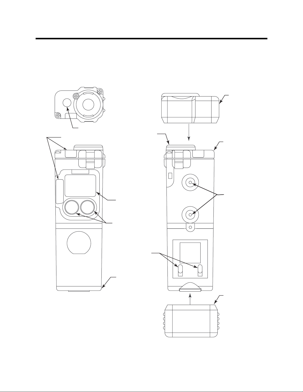
Description
d
This section describes the components of the 01 Series. These
components include the 01 Series’ protective rubber boots, case,
membrane retainer and filter disks, sensor retainer, sensor, LCD, control
buttons, printed circuit boards, alarm lights, buzzer, vibrator, and batteries.
Alarm Lights
Buzzer Opening
Membrane
Retainer
Sensor En
Boot
Sensor
Retainer
POWER
MODE
CO
CO-01
AIR
LCD
Control Buttons
Battery Charging
Contacts
Battery Cover
Threaded
Inserts
Battery End
Boot
Figure 1: Components of the 01 Series
01Series Operator’s Manual Description • 4
Page 10

Protective Rubber Boots
A protective rubber boot is installed over each end of the 01 Series. The
sensor end boot fits over the sensor cover end of the 01 Series and the
battery end boot fits over the battery cover end of the 01 Series.
Case
The 01 Series’ sturdy, high-impact plastic case is blue in colo r. The case is
suitable for use in many environmental conditions, indoors and out. The
unit is dust proof and weather resistant.
The front of the case has an L CD (liqui d crystal display) tha t shows various
readings, which are described under “LCD” in this section. T o the left of the
LCD is an alarm light. Below the LCD are two black control buttons. The left
button is labeled “POW ER /M OD E” and the right button is labeled “AIR ”.
On top of the case and to the left is the 01 Series’s buzzer, which is located
inside the unit. To the right of the buzze r is the senso r . The senso r is held in
place by the senso r re tainer (the top of the case for th e 01 Series) and two
screws. The sensor is prote cted from dirt and m oisture by the sensor cover .
The sensor cover is secured by a membran e retainer and a single screw. In
the case of the CO-01, a charcoal filter is provided under the sensor cover
to protect the CO sensor from hydrogen sulfide and certain hydrocarbons.
To the left of the sensor and below the buzzer, is a second alarm light,
which is also visible from the front of the case.
The battery compartment is located on the bottom of the case. Access to
the compartment is accomplished by turning the captive battery cover
screw counterclockwise and by removing the battery compartment door.
There are two threaded holes on the back of the case. These are used to
mount the optional alligator clip or belt clip.
Toward the bottom of the back are two battery charging contacts. These
contacts are used to charge a Ni-cad battery pack which is available.
Consult RKI Instruments, Inc. for information about this option.
The wrist strap connects to the back of the case on the left side, near the
top of the unit.
5 • D e s c r i p t i o n 01 Series Operator’s Manual
Page 11

Alligator and Belt Clips
The 01 Series is available with two types of clips, the alligator clip and the
belt clip. Both are illustrated in Figure 2 below.
Belt Clip
Alligator Clip
Figure 2: Alligator & Belt Clips
The alligator clip can be used to attach the 01 Series to clothing or a belt.
Teeth in the clip’s jaws prevent the unit from slipping off. The belt clip is
used to easily clip the 01 Series on a belt.
Membrane Retainer/Sensor Cover
The membrane retainer is held in place by a single Phillips screw. Beneath
the membrane retainer is a paper-like filter disk, the sensor cover. The
sensor cover protects the sensor from dirt and moisture.
The sensor cover fits into a recessed area and is held in place by the
membrane ret ainer. The sensor cover should be inspect ed perio dically a nd
replaced if contaminated by dirt or moisture. Refer to the Maintenance
section for sensor cover replacement instructions.
Charcoal Filter Disk in CO-01
The CO-01 includes a charcoal filter disk which is located in a recessed
area beneath the sensor cover. The charcoal filter disk removes gases
from the sampled air that will cause a response on the CO sensor such as
H2S and certain hydrocarbons. If false or elevated CO readings are
01Series Operator’s Manual Description • 6
Page 12

noticed, especially in the presence of H2S, change the charcoal filter disk
(see the Maintenance section for instructions).
Sensor Retainer
The sensor retainer holds th e sensor in place. It is att ached to the top of the
case by two Phillips screws. The sensor retainer also covers the buzzer.
Should the sensor require replacement, refer to the Maintenance section
for sensor replacement instructions. The buzzer, however, is not field
replaceable.
The sensor retainer has a single diffusion port through which ambient air
reaches the sensor. Recessed areas in the sensor retainer accept the
charcoal filter disks (CO-01 only) and the sensor cover. The membrane
retainer is installed to the top of the sensor retainer with a single Phillips
screw.
Sensor
The 01 Series uses either an oxygen, CO, or H2S sensor. The sensor is
protected by the white sensor cover which is held in place by the
membrane ret ainer . The sensor cover allows ambient ai r to dif fuse p ast it to
the sensor. The three sensors used in the three 01 Series models use
different detection principles as described below.
Oxygen Sensor
The oxygen sensor is a galvanic type of sensor. A membrane covers the
cell and allows gas to diffuse i nto the cell at a rate proportion al to the par tial
pressure of oxygen. The oxygen react s in the cell and prod uce s a volta ge
proportion al to the concentration of oxygen. The voltage is measured by
the 01 Series’ circuitry, converted to a measurement of gas concentration,
and displayed on the LCD.
CO and H
The CO and H2S sensors are electrochemical sensors that consist of two
precious metal electrodes in an acid electrolyte. A gas permeable
membrane covers the sensor face and allows gas to diffuse into the
electrolyte. The gas reacts in the sensor and produces a current
proportional to the concentration of the target gas. The current is amplified
by the 01 Series’ circuitry, converted to a measurement of gas
concentration, and displayed on the LCD.
S Sensors
2
LCD
The LCD is visible through the front of the case. When the 01 Series is in
Measuring Mode, the target gas concentration, battery condition, and
alarm indications are displayed on the LCD. Various other items are
displayed when th e LCD is in other modes, such as Calibration Mode.
7 • D e s c r i p t i o n 01 Series Operator’s Manual
Page 13

When either of the two control buttons are pressed, the LCD backlight
comes on for 20 seconds.
Control Buttons
Below the LCD are two control buttons: POWER/MODE and AIR. The
POWER/MODE button turns the 01 Series on and off. The functions
performed by the control buttons are summarized in the following table:
Table 2: 01 Series Control Buttons
Button Function
• Turns the unit on and off.
• Turns the LCD back light on.
• Displays STEL and TWA reading s (HS-01 & CO-
01).
POWER/MODE
• Displays peak readings (high for HS-01& CO01and low & high for OX-01).
• Resets the alarm circuit (gas alarms).
• Enters Calibration Mode with the AIR button.
• Enters Alarm Adjustment Mode with the AIR
button.
• Turns the LCD back light on.
• Adjusts LCD readings when the fresh air
adjustment is performed.
• Enters Calibration Mode with the POWER/MODE
AIR
button.
• Enters Alarm Adjustment Mode with the POWER/
MODE button.
• Increases settings when the unit is in Alarm
Adjustment Mode or Calibration Mode.
Printed Circuit Boards
The primary function of the 01 Series’s printed circuit boards is to amplify
the signal sent to them from the sensor, convert the signal to a meaningful
measurement of gas concentration, display the gas concentration on the
LCD, store STEL, TWA, and peak gas readings, and activate the alarm
circuit if an alarm point has been reached. They monitor battery level,
battery failure, and sensor failure. They also control various operating
modes of the unit.
NOTE: The printed circuit boards contain no user serviceable parts.
01Series Operator’s Manual Description • 8
Page 14

Alarm Lights
The 01 Series has two red LED alarm lights. They alert you to gas, low
battery, and sensor failure alarms. The smaller of the two lights is square,
has a frosted plastic cove r, and is located at the top of the unit to th e left of
the membrane retainer. Th e la rg er al ar m li g ht is re ctangular in shape, has
a diamond-grid pattern etched into the plastic cover, and is located to the
left of the LCD on the front of the case.
Buzzer
A solid-state ele ctronic buzzer is mounted inside the 01 Seri es. An openin g
in the sensor retainer on top of the case allows the buzzer’s sound to
emanate from the case. The buzzer sounds for gas alarms, unit
malfunctions, and dead battery alarm. It also serves as an indicator during
normal use of the various LCD display options.
Vibrator
A vibrating motor (vibrator) is mounted inside the 01 Series. The vibrator
vibrates momentarily during the power-up sequence and for gas alarms.
Batteries
Two AAA-size alkaline batteries run the 01 Series. At 25°C the alkaline
batteries last at least 3,000 hours. The battery icon on the LCD shows
remaining batter y lif e .
When the 01 Series detects low battery voltage, a low battery warning is
activated. When battery voltage is too low for normal operation, the 01
Series sounds a dead battery alarm.
The alkaline batteries can be replaced by removing the battery door at the
bottom of the case. Turn the captive battery cover screw counterclockwise
to release the door.
WARNING: To prevent ignition of a hazardous atmosphere, batteries
must only be changed in an area known to be
nonhazardous.
A Ni-cad battery pack and charger are available. Contact RKI Instruments,
Inc. for information about this option.
9 • D e s c r i p t i o n 01 Series Operator’s Manual
Page 15

Start Up
This section explains how to start up the 01 Series and to get it ready for
operation.
Start-up Procedure
1. Press and hold the POWER/MODE button for three seconds to turn on
the 01 Series.
For several seconds, all elements of the LCD display and the LCD
backlight turn on. The vibrator activates briefly, and it then shuts off.
The alarm lights fl ash on and the buzzer sounds, and then they both
turn off.
2. The 01 Series then displays the target gas (H2S, CO, or O2) before
displaying the battery voltage. The buzzer sounds again after the
battery voltage is displayed.
CAUTION: If the unit gives a low battery warning or dead battery alarm,
change the alkaline batteries before using the unit.
3. The sensor inside the 01 Series begins operating and the concentration
of the target gas is displayed on the LCD. The 01 Series is now in
Measuring Mode. The target gas concentration is displayed. The
backlight turns off after 20 seconds.
Performing a Fresh Air Adjustment
Before using the 01 Series, set the fresh air reading. Performing this
adjustment ensures accurate gas readings in the monitoring environment.
1. Find a fresh air environment of normal oxygen content (20.9%) that is
free of toxic or combustible gases.
2. With the unit on and in Measuring Mo de, press and ho ld the AIR butto n.
The LCD displays “hold” prompting you to hold the AIR button.
3. Release the A IR button when the LCD displays “AdJ”. The unit will set
the reading to 0 ppm (20.9% for the OX-01) and return to Measuring
Mode.
Turning Off the 01 Series
1. Press and hold the POWER/MODE button for about five seconds to
turn off t he un it. Th e buzze r w ill soun d wh ile the P OWER/ MODE button
is being pressed before the unit turns off.
2. Release the bu tton when the LCD is blank. The unit is off.
01Series Operator’s Manual Start Up • 10
Page 16

Operation
This section describes the normal operation of the 01 Series in Measuring
Mode. It explains how the unit can be used to display peak, STEL, and
TWA readings for the HS-01 and CO-01, and minimum and maximum
readings for the OX-01. It also covers alarm indications.
Measuring Mode
To put the 01 Series in Measuring Mode, assuming the unit is off, press and
hold the POWER/MODE button for three seconds.
Before continuing, it is advisable to perform a fresh-air adjustment in a
fresh-air environment. Making this adjustment ensures accurate gas
readings in the monitoring environment. Refer to “Start Up” for more
information.
In Measuring Mode, the battery level and target gas concentration are
displayed on the LCD. The battery icon has four bar s visible when the
batteries have a full charge. As the battery charge decreases, the bars will
gradually disappear, one by one.
The target gas concentration is displayed below the battery icon. On the
CO-01, CO is displayed in parts per million (ppm). On the HS-01, H2S is
displayed in ppm. On the OX-01, oxygen is displayed as volume percent
Battery level
Gas concentration
0.0
ppm
Figure 3: LCD in Measuring Mode
Displaying the Peak, STEL, and TWA (CO-01 & HS-01)
You can displ ay the Peak, STEL, and TWA readings on the CO-01 and
HS-01 when th e 01 Seri es is i n Measu ring Mo de using t he POWE R/MODE
button. STEL is an acronym for short-term exposure limit, and it is the
average reading of the target gas (H2S or CO) during the last 15 minutes.
TWA is an acronym for time-weig hted average, and it is the aver age
reading for the target gas (H2S or CO) during the last eight (8) hours. If
eight (8) hours has not elapsed since the unit was turned on, the TWA is
still calculated over eight hours, with the missi ng time assigned a zero (0)
value for the readi ng s. Si m ila r ly, if the unit has not been on for 15 m inutes,
the missing time is assigned a 0 value and the STEL is calculated over 15
minutes. The Peak, STEL, and TWA readings are cleared when the unit is
turned off.
11 • Operation 01 Series Operator’s Manual
Page 17

1. The unit must be in Measuring Mode. The current gas concentration
should be displayed on the LCD.
2. Press and release the POWER/MODE button to enter Peak Gas
Display Mode. The LCD backlight will activate and the LCD will display
the peak gas reading. A small peak symbol is displayed in the upper left
corner of the LCD.
3. Press and release the POWER/MODE button again to enter STEL
Display Mode. This will display the STEL reading. The word “STEL” is
displayed in the middle of the LCD above the reading.
4. Press and release the POWER/MODE button again to enter TWA
Display Mode. This will display the TWA reading. The word “TWA” is
displayed in the middle of the LCD above the reading.
5. Press and release the POWER/MODE button once again to return the
unit to Measurin g Mode.
NOTE: If you do not press a button for 20 seconds while displaying the
peak gas reading, the unit will return to Measuring Mode
automatically and the backlight will turn off.
Displaying the Min and Max (OX-01)
You can display the minimum (Min) and maximum (Max) readings on the
OX-01 when the it is in Measuring Mode using the POW ER /M OD E b utto n.
The Min and Max readings are cleared when the unit is turned off.
1. Make sure the OX-0 1 is in Measuring Mode. The oxygen con centration
should be displayed on the LCD.
2. Press and release the POWER/MODE button to enter Min Display
Mode. This will activate the LC D backli gh t an d displ a y the M in re ading.
A small Min symbol is displayed in the upper left corner of the LCD.
3. Press and release the POWER/MODE button again to enter Max
Display Mode. This will display the Max reading. A small Max symbol is
displayed in the upper left corner of the LCD.
4. Press and release the POWER/MODE button once again to return to
Measuring Mode.
NOTE: If you do not press a button for 20 seconds while displaying the
Min or Max readings, the unit will return to Me asuring Mode
automatically and the backlight will turn off.
01Series Operator’s Manual Operation • 1 2
Page 18

Alarms
This section covers alarm indications. It also tells you how to reset the 01
Series after an alarm has occurred and how to respond to an alarm
condition.
Alarm Indications
The 01 Series will sound an ala rm, flash its alarm lights, and vibrate when
the target gas con centration rises above t he low alar m point. The 01 S eries
also sounds an alarm, flashes its alarm lights, and vibrates when the high
alarm point is reached. In addition, the 01 Series also has a low battery
warning, a dead battery alarm, an over range alarm, a sensor failure alarm,
and a system failure alarm. See Table 3 below for a description of each
alarm indicat i on.
Table 3: Alarm Types and Indications
Alarm T ype LCD Indications Other Indications
Low Alarm
Concentration of gas
rises above the low
alarm point, or for the
OX-01, falls below the
low alarm point.
High Alarm
Concentration of gas
rises above the high
alarm point.
TWA or STEL
(CO-01 & HS-01 Only)
Concentration of CO
S rises above the
or H
2
TWA or STEL alarm
point.
• Gas reading
flashes.
• Back light turns on.
• Gas reading
flashes.
• Back light turns on.
• Back light turns on.
• Gas reading
flashes.
• TW A or STEL
blinks to the left of
the battery icon.
• If the unit is in both
TWA alarm and
STEL alarm, both
TWA an d STEL will
be displayed.
• Pulsing tone occurs
once per second.
• Unit vibrates once
per second.
• Alarm lights flash
once per second.
• Pulsing tone occurs
twice per second.
• Unit vibrates twice
per second.
• Alarm light flashes
twice per second.
• Pulsing tone once
per second.
• Unit vibrates once
per second.
• Alarm light flashes
once per second.
13 • Operation 01 Series Operator’s Manual
Page 19

Table 3: Alarm Types and Indications
Alarm T ype LCD Indications Other Indications
Over Range
Concentration of gas
rises above the
• Gas reading
replaced by blinking
brackets.
measuring limit of the
01 Series. (Or there
• Back light turns on.
could be a problem
with the unit.)
Low Battery Warning • Last remaining bar
on the right in
battery icon
flashes.
Dead Battery Alarm • Gas reading
replaced by FAIL.
• Battery icon
flashes.
Sensor Failure • Gas reading
replaced by FAIL.
• Pulsing tone occurs
once per second.
• Unit vibrates once
per second.
• Alarm light flashes.
•None
• Double pulsing to ne
(two pulses in quick
succession) occurs
once a second.
• Double pulsing to ne
(two pulses in quick
succession) once a
second.
System Failure • Gas reading
replaced by FAIL.
• SYS displays below
FAIL.
• Double pulsing to ne
(two pulses in quick
succession) once a
second.
Resetting Gas Alarms
To reset a gas alarm, press the POWER/MODE button after the gas
reading falls below the low alarm point. If a TWA or STEL alarm has be en
activated, it cannot be reset unless you turn off the unit.
NOTE: Even though the gas concentration may have returned t o normal
or may have fallen below the low alarm point, the alarm
indications will continue until you have rese t the a larm using the
POWER/MODE button.
01Series Operator’s Manual Operation • 1 4
Page 20

Responding to Alarms
This section describes response to gas, over range, battery, sensor failure,
and system failure alarms.
Responding to Gas Alarms
1. Follow your established procedure for an increasing gas condition or a
decreasing oxygen condition.
2. Reset the alarm by pressing and rel easing the POWER/MODE button
after the alarm condition has been cleared.
Responding to an Over Range Alarm
WARNING: An over range condition may indicate an extreme toxic
gas or oxygen concentration. Confirm the gas
concentration with a different 01 Series or with another
gas detecting device.
1. Follow your established procedure for an increasing gas condition.
2. Reset the alarm by pressing and rel easing the POWER/MODE button
after the alarm condition has cleared.
3. Calibrate th e 01 Series as described in the calibration section of this
manual.
4. If the over range condition continues, you may need to replace the
sensor.
5. If the over range condition continues aft er you have replaced the
sensor, contact RKI Instruments, Inc. for further instructions.
Responding to Battery Alarms
WARNING: The 01 Series is not operational as a gas monitoring
device during a dead battery alarm. Take the 01 Series to
a non-hazardous area and change the alkaline batteries
as described in “Replacing the Batteries”.
The 01 Series is fully functional in a low battery warning condition.
However, only a couple of days of operation may remain depending on
certain conditions such as alarm occurrences an d how often the backlight
comes on.
NOTE: Alarms and the back light feature consume battery power and
reduce the amount of operating time remaining.
When a low battery warning occurs, change the batteries as soon as
15 • Operation 01 Series Operator’s Manual
Page 21

possible. Refer to the instructions in “Replacing the Batteries” for more
information.
Responding to a Sensor Failure Alarm
1. Try calibrating the 01 Series first, as described in “Calibration”, before
replacing the sensor.
2. If the sensor failure continues, replace the sensor as described in
“Replacing the Sensor”.
3. If the gas sensor failure conditio n contin ues af ter you have replaced the
gas sensor, contact RKI Instruments, Inc. for further instructions.
Responding to a System Failure Alarm
1. If a system failure occurs, try turning the unit off then on again.
2. If the unit remains in system failure, contact RKI Instruments, Inc. for
further instructions.
Alarm Points
The 01 Series allows you to display and set the alarm points. The alarm
point factory settings are summarized below:
Table 4: Alarm Points of the 01 Series
Model Low Alarm High Alarm STEL TWA
CO-01 25 ppm 50 ppm 200 ppm 25 ppm
HS-01 10.0 ppm 30.0 ppm 15.0 ppm 10.0 ppm
OX-01 19.5%
Decreasing
In the table above, Low Alarm and High Alarm for the CO-01and HS-01
refer to a rising concentration of the target gases. The Low Alarm is
triggered at the Low Alarm concentration listed in the table. For the CO-01
that would be 25 ppm CO, and for the HS-01 that would be 10.0 ppm. The
High Alarm is triggered when the High Alarm concentration is reached.
For the OX-01, Low Alarm is triggered when the concentration of oxygen
falls below 19.5%. When the concentration of oxygen rises above 23.5%,
High Alarm is activated.
23.5%
Increasing
N/A N/A
Displaying and Adjusting the Alarm Points
1. Make sure the 01 Series is turned off. The LCD should be blank.
2. Press and hold the AIR button, then press and hold the POWER/MODE
button.
01Series Operator’s Manual Alarm Points • 16
Page 22

3. As soon as segments appear on the display (approximately one
second), release the AIR button. When the unit “beeps,” release the
POWER/MODE button to put the 01 Series into Alarm Point Adjustment
Mode. The LCD should display the low alarm setting and the battery
level.
Rising
Alarm
.
Battery
level
Alarm point
10.0
Alarm
Name
Figure 4: LCD in Alarm Adjustment Mode, CO-01 & HS-01
Falling
Alarm
LO
.
19.5
Alarm
Name
Figure 5: LCD in Alarm Adjustment Mode, OX-01
LO
ppm
Battery
level
Alarm point
%
NOTE: If the LCD should show “CAL” in the lower left corner, the 01
Series is in Calibration Mode. You will need to press and hold the
POWER/MODE butto n to tur n of f th e uni t. Beg in agai n with step 2
above.
4. While the 01 Series is displaying the low alarm point, use the AIR
button to change the setting. Pressing and releasing the AIR button in
quick succession increases the low alarm point one number at a time.
Pressing and holding the AIR button increases the low alarm point by
ten percentage points at a time.
NOTE: If you pass the desir ed alarm point sett ing, continue increa sing the
alarm point until it reaches the maximum setting, at which point
the alarm point number will “wrap around” to its minimum setting.
5. Press and release the POWER/MODE button to display the high alarm
point in the LCD. If you h ave ch an ged the low alarm point setting, it will
be saved automatically after you press the POWER/MODE button.
17 • A l a r m P o i n t s 01 Series Operator’s Manual
Page 23

NOTE: If you press and hold the POWER/MODE button for too long
(about five seconds), you will turn off the unit.
6. Use the AIR button to change the hi gh alarm point setting. Pr essing and
releasing the AIR button in quick succession increases the high alarm
point one number at a time. Pressing and holding the AIR button
increases the high alarm point at a faster rate.
NOTE: You can only cycle through the alarm points once before the 01
Series goes into its start-up sequence, which then places the unit
in Measuring Mode. If you want to cycle through the alarm points
again, press and hold the POWER /MODE butt on to turn of f the 01
Series. Then begin with step 2 above to put the unit back into
Alarm Point Adjustme nt Mode.
7. When you are finished viewing or adjus ting the alarm point settings,
press and release the POWER/MODE button until the ROM number of
the unit appea rs on the LC D. ( The R OM is t he co mpon ent that cont ai ns
the software that runs the 01 Series.) The 01 Series will then go into its
start-up sequence followed by Measuring Mode.
01Series Operator’s Manual Alarm Points • 18
Page 24

Calibration
This section covers the calibration of the 01 Series. Setting the fresh air
reading is described first followed by setting the span (CO-01 and HS-01)
or zero (OX-01) reading. You are also told what is needed to complete the
task and how to assemble the calibration kit.
WARNING: Use a 0.5 LPM (liters per minute) fixed flow regulator
Calibration Frequency
The optimum frequency of calibration depends heavily on how the 01
Series is used. For example, instruments used daily may need to be
calibrated weekly or monthly, while instruments that are used only a few
times a year may need to be calib rated before ea ch use. T ypica l calibration
frequencies range from monthly to quarterly. Make sure to develop a
calibration schedule tailored to your application.
when calibrating. Using a different flow rate may
adversely affect the accuracy of the calibration.
Setting the Fresh Air Reading
You will need to set the fresh air reading first before setting the span (zero
for OX-01) reading.
1. Find a fresh air environment of normal oxygen content (20.9%) that is
free of toxic or combustible gases.
2. With the unit on and in Measuring Mo de, press and ho ld the AIR butto n.
The LCD displays “hold” prompting you to hold the AIR button.
3. Release the A IR button when the LCD displays “AdJ”. The unit will set
the reading and return to Measuring Mode. On the CO-01 and HS-01,
the unit will set the reading to 0 ppm and on the OX-01 it will set the
reading to 20.9% oxygen
Setting the Spa n (Zero for OX-01) Reading
This section tells you how to set the span reading on the CO-01 and HS-01
and the zero reading on the OX-01 using Calibration Mode.
Preparation
Set the fresh air reading as described in “Setting the Fresh Air Reading.”
You will also need the supplies listed below. A calibration kit is available
from RKI Instruments, Inc. for each 01 Series model (see “Parts List”).
• A gas cylinder with an appropriate concentration of the target gas for
the CO-01 or HS-01, or a cylinder of 100% nitrogen for the OX-01.
19 • Calibration 01 Series Operator’s Manual
Page 25

NOTE: On the OX-01, instead of 100% nitrogen (0% oxygen), it is
allowable to use higher than 0% oxygen to set the zero level. RKI
Instruments, Inc. recommends 18% oxygen or lower.
• To carry out the calibration, you will need a fixed-flow regulator with a
flow rate of 0.5 LPM (liters per minute), non-absorbent tubing, and t he
calibration adapter that will fit over the 01 Series’ sensor.
Assembling the Calibration Kit
WARNING: Calibrate the 01 Series in a non-hazardous environment.
1. Attach the calibration adapter to the top of the 01 Series. The calibration
adapter opens up like a clothes p in. It fits over the 01 Series’s gas
sensor port on top of the sensor retainer and secures itself there by
clamping to the front and back of the 01 Series.
2. Attach the calibration tubing to the calibration adapter, and then attach
the opposite end of the tubing to the regulator.
NOTE: Do not attach the regulator to the gas cylinder at this time.
Setting the Span Reading (Zero Reading for OX-1)
1. Make sure you have set the fresh air reading and have set up the
calibration kit as described in the procedures above.
2. Make sure the 01 Series is off.
3. Press and hold the AIR button, and then press and hold the POWE R/
MODE button. Release both buttons when you hear a “beep”. The unit
is in Calibration Mode and the LCD displays “CAL” in the lower left and
the battery level in the up per right. It also displays the gas concentration
that the unit expects you to use, the calibration value, when setting the
span.
4. If necessary, use the AIR button to adjust the calibration value to the
desired setting. The calibration value must match the gas concentration
in the calibration cylinder.
5. Press the POWER/MODE button to accept the calibration value. The
current gas reading is displayed , and “CAL” will blink in the lower left
corner of the LCD. The unit is now in Span Adjustment Mode.
If you want to cancel the calibration while in Span Adjustment Mode,
press and hold th e AIR ke y for 3 seconds an d the un it will not make any
span adjustments and begin its startup sequence.
01Series Operator’s Manual Calibration • 20
Page 26

NOTE: If one of the control buttons is not pressed within 10 minutes, the
unit will return to Measuring Mode automatically.
6. Attach the regulator to the gas cylinder. The fixed-flow regulator
automatically begins introducing the calibration sample to the sensor.
7. Let the gas flow for two minutes. After two minutes, press the POWER/
MODE button. The unit will adjust the span (CO-01 and HS-01) or zero
(OX-01) based on the calibration value that was saved in step 5 above.
As soon as the unit makes the calibration adjustment, it will begin its
start-up sequence, and then it will enter Measuring Mode.
NOTE: If the 01 Series displays “FAIL” on the LCD after you press the
Power/MODE button, the sensor output may be too low or too
high or there may be a problem with the calibrat ion gas or
calibration kit setup. Refer to the Troubleshooting s ection in
Maintenance t o solve the problem.
8. Remove the regulator from the gas cylinder and the calibration adapter
from the unit.
NOTE: If the gas reading is high enough (low enough for the OX-01)
when the unit enters Measuring Mo de, an alarm condition will
occur. If this occurs, reset the alarm using the POWER/MODE
button when the gas reading falls below (rises above for the OX-
01) the alarm point.
21 • Calibration 01 Series Operator’s Manual
Page 27

Maintenance
This section describes tro ubleshooting procedures for the 01 Series. It also
describes how to change the 01 Series’s batteries as well as how to
replace the sensor and sensor cover.
WARNING: RKI Instruments, Inc. recommends that service,
Troubleshooting
The troubleshooting table describes error messages, symptoms, probable
causes, and recommended actions for problems you may encounter with
the 01 Series.
calibration, and repair of RKI instruments be performed
by personnel properly trained for this work. Replacing
sensors and other parts with original equipment does not
affect the intrinsic safety of the instrument.
Table 5: Troubleshooting the 01 Series
Symptoms
• The LCD is
blank.
• The LCD shows
abnormally high
readings but
other gas
detection
instruments do
not.
Probable
Causes
• The unit may
have been
turned off.
• The alkaline
batteries may
need to be
replaced.
• The unit may
need to be
recalibrated.
• The sensor
may need
replacement.
Recommended Action
1. To turn on the unit, press
and hold the POWER/
MODE button.
2. If the unit does not turn on,
replace the alkaline
batteries.
3. If the difficulties continue,
contact RKI Instruments,
Inc. for further instruction.
1. Recalibrate t he unit.
2. Replace the sensor and
calibrate the unit.
3. If the difficulties continue,
contact RKI Instrument s for
further instruction.
01Series Operator’s Manual Maintenance • 22
Page 28

Table 5: Troubleshooting the 01 Series
Symptoms
• “FAIL” displays
during span
adjustment.
Probable
Causes
• The calibration
value may not
match the
cylinder gas
concentration.
• The sample
gas is not
reaching the
sensor
because of a
bad
connection.
• The calibration
cylinder may
be out of gas
or is outdated.
• The sensor
may need
replacement.
Recommended Action
1. Check all calibration tubing
for leaks or for any bad
connections.
2. Make sure the 01 Series
has been properly set up
for calibration.
3. Verify that the calibration
cylinder contains an
adequate supply of fresh
test sample.
4. If the fail condition
continues, replace the
sensor.
5. If the difficulties continue,
contact RKI Instruments,
Inc. for further instruction.
• “FAIL SYS” is
displays on the
LCD
• A microprocessor failure has
occurred.
1. Turn off the unit and turn it
on again.
2. If difficulties continue,
contact RKI Instruments,
Inc.
Replacing the Batteries
WARNING: To prevent ignition of a hazardous atmosphere, batteries
must only be changed in an area known to be
nonhazardous.
Replace the batt eries when the battery icon indicates that
the unit is in low battery warning. When in low battery
warning, only on e battery level indication bar is di spl ay ed i n
the battery icon on the LCD, and this icon will be flashing.
To Replace the Batteries
1. Verify that the 01 Series is off.
2. Remove the battery end protective rubber boot.
23 • Maintenance 01 Series Operator’s Manual
Page 29

3. Rotate the captive battery cover screw counterclockwise to remove
battery compartment door.
AIR
CO-01
MODE
POWER
CO
Figure 6: Removing the Battery Compartment Door
4. Carefully remove the old alkaline batteries.
5. Carefully install the new AAA alkaline batteries. Follow the battery
diagram inside the battery compartment.
6. Reinstall the battery cover.
NOTE: If the unit has been without batteries or if the old batteries have
been dead for a n exten ded pe rio d, al low 10 min utes after the new
batteries have been installed for the sensor to stabilize.
Replacing the Sensor
WARNING: Replace the sensor in a non-hazardous environment.
1. Verify that the 01 Series is off.
2. Remove the sensor end protective ru bber boot.
3. With a small Phillips screwdriver, carefully unscrew the two screws that
hold the sensor retainer in place.
Sensor Retainer
Sensor
AIR
CO-01
MODE
POWER
CO
Figure 7: Removing the Sensor Retainer
01Series Operator’s Manual Maintenance • 24
Page 30

4. Carefully remove the old sen sor from the sensor socket.
5. Carefully insert the replacement sensor in the socket. Make sure the
sensor face with the colored ring is facing up.
Tab
Tab
Note: Oxygen sensor is not keyed.
Unit shown without Sensor Retainer
Allign slots in CO & H2S
sensors with tabs in case.
Figure 8: Replacing the Sensor
CAUTION: When replacing the sensor, verify that the sensor is properly
aligned with its socket before inserting it into the socket. The
CO and H2S sensors have alignment slots which match up
with alignment tabs in the sockets. Forcing a sensor into its
socket may damage the sensor or the socket.
6. Reinstall the sensor retainer.
7. Allow 10 minutes for the new se nsor to stabilize.
8. Calibrate the new sensor as described in the calibration section of this
manual.
Replacing the Sensor Cover and Charcoal Filter
WARNING: Replace the sensor cover and charcoal filter in a non-
hazardous environment.
When replacing the sensor filters, it is recommended that you replace all
filters at the same time.The HS-01 and OX-01 only have the sensor cover.
The CO-01 has the sensor cover and the charcoal filter.
1. Verify that the 01 Series is off.
2. With a small Phillips screwdriver, carefully unscrew the single screw
that holds the membrane retainer in place.
25 • Maintenance 01 Series Operator’s Manual
Page 31

Figure 9: Replacing the Sensor Filters
3. Rotate the me mbrane reta iner abo ut one-qu arter tu rn counter clockwise
to remove it from the sensor retainer (the top of the unit).
4. Carefully remove the sensor cover from the recess in the senor retainer.
If you have a CO-01, also remove the charcoal filter.
5. If you have a CO-01, in st a l l a char co al fil ter into the smaller recess and
make sure they ar e properly seated in the recess. Then insert one
sensor cover in the larger recess (all models).
CAUTION: Be very careful not to push the charcoal filter disk too far into
the recess in the sensor retainer. Lay the disk carefully in the
opening on top of the small tabs in the recess.
6. Reinstall the membrane retainer.
01Series Operator’s Manual Maintenance • 26
Page 32

Parts List
Table 6lists replacement parts and accessori es for the 01 Seri es.
Table 6: Parts List
Part Number Description
06-1248RK Calibration kit tubing (speci fy l eng th in feet)
07-6009RK Gasket for battery cover
10-1099RK Screw, M2X 4mm pan head Phillips, stainless
steel, for membrane retainer
10-1105RK Screw, M2X 8mm pan head Phillips, stainless
steel, for sensor retainer
10-1141RK Screw,M2.5 x 3mm pan head Phillips, stainless
steel, for alligator and belt clip installation.
13-0112RK Wrist strap
13-0114RK Alligator clip
13-0213RK Belt Clip
13-1115RK Captive battery cover screw
20-0316RK Rubber boot, sensor end
20-0317RK Rubber boot, battery end
21-1848RK Membrane retainer
21-1849RK Sensor retainer
33-0166RK Sensor cover dis k membrane, 10 pack
33-7106RK Filter disk, charcoal, 10 pack
49-1110RK AAA size alkaline battery
81-0064RK-01 Calibration cylinder, 50 ppm CO in air, 34 liter
steel
81-0078RK-01 Calibration cylinder, 100% nitrogen,34 liter, steel
81-0151RK-04 Calibration cylinder, 25 ppm H
S in nitrogen,34
2
liter, aluminum
81-1003RK Regulator, fixed flow, 0.5 LPM, for 17/34 liter
steel cylinder
27 • P a r t s L i s t 01 Series Operator’s Manual
Page 33

Table 6: Parts List
Part Number Description
81-1004RK Regulator, fixed flow, 0.5 LPM, for 58/34 liter
aluminum cylinder, 103 liter steel cylinder
81-1104RK Calibration adapter for 01 Series & GasWatch 2
81-CO01-LV Calibration kit for CO-01, one 34 liter steel gas
cylinder (50 ppm CO in air), regulator , calibration
cup, case, tubing
81-HS01-LV Calibration kit for HS-01, one 34 liter aluminum
gas cylinder (25 ppm H2S in nitrogen), regul ator ,
calibration c up, case, & tubing
81-OX01-LV Calibration kit for OX-01, one 34 liter steel gas
cylinder (100% nitrogen), regulator, calibration
cup, case, tubing
ES-1821 Carbon monoxide senso r
ES-1821L Carbon monoxide sensor, for low humidity use
ES-1827 Hydrogen sulfide sensor
ES-1827L Hydrogen sulfide sensor, for low humidity use
OS-BM2 Oxygen sensor
01Series Operator’s Manual Parts List • 28
 Loading...