

Page 1

SDM-E2 Docking Station
Standalone Configuration
Operator’s Manual
Part Number: 71-0224RK
Revision: F
Released: 5/16/17
www.rkiinstruments.com
Page 2

Warranty
RKI Instruments, Inc. warrants gas alarm equipment sold by us to be free from
defects in materials and workmanship, and performance for a period of one year from
date of shipment from RKI Instruments, Inc. Any parts found defective within that
period will be repaired or replaced, at our option, free of charge. This warranty does
not apply to those items which by their nature are subject to deterioration or
consumption in normal service, and which must be cleaned, repaired, or replaced on
a routine basis. Examples of such items are:
Absorbent cartridges Batteries
Pump diaphragms and valves Filter elements
Fuses
Warranty is voided by abuse including mechanical damage, alteration, rough
handling, or repairs procedures not in accordance with the instruction manual. This
warranty indicates the full extent of our liability, and we are not responsible for
removal or replacement costs, local repair costs, transportation costs, or contingent
expenses incurred without our prior approval.
THIS WARRANTY IS EXPRESSLY IN LIEU OF ANY AND ALL OTHER
WARRANTIES AND REPRESENTATIONS, EXPRESSED OR IMPLIED, AND
ALL OTHER OBLIGATIONS OR LIABILITIES ON THE PART OF RKI
NSTRUMENTS, INC. INCLUDING BUT NOT LIMITED TO THE WARRANTY
I
OF MERCHANTABILITY OR FITNESS FOR A PARTIC ULAR PURPOSE. IN
NO EVENT SHALL RKI INSTRUMENTS, INC. BE LIABLE FOR INDIRECT,
INCIDENTAL, OR CONSEQUENTIAL LOSS OR DAMAGE OF ANY KIND
CONNECTED WITH THE USE OF ITS PRODUCTS OR FAILURE OF ITS
PRODUCTS TO FUNCTION OR OPERATE PROPERLY.
This warranty covers instruments and parts sold to users only by authorized
distributors, dealers, and representatives as appointed by RKI Instruments, Inc.
We do not assume indemnification for any accident or damage caused by the
operation of this gas monitor and our warranty is limited to replacement of parts or our
complete goods.
Warranty
Page 3

Table of Contents
Chapter 1: Introduction . . . . . . . . . . . . . . . . . . . . . . . . . . . . . . . . . . . . . . . . . . . . . . . . . 1
Overview . . . . . . . . . . . . . . . . . . . . . . . . . . . . . . . . . . . . . . . . . . . . . . . . . . . . . . . . 1
About the SDM-E2 . . . . . . . . . . . . . . . . . . . . . . . . . . . . . . . . . . . . . . . . . . . . . . . . 1
System Requirements. . . . . . . . . . . . . . . . . . . . . . . . . . . . . . . . . . . . . . . . . . . . . . 2
Specifications . . . . . . . . . . . . . . . . . . . . . . . . . . . . . . . . . . . . . . . . . . . . . . . . . . . . 3
About This Manual . . . . . . . . . . . . . . . . . . . . . . . . . . . . . . . . . . . . . . . . . . . . . . . . 4
Cautions & Safety Information . . . . . . . . . . . . . . . . . . . . . . . . . . . . . . . . . . . . . . . 4
Chapter 2: Description . . . . . . . . . . . . . . . . . . . . . . . . . . . . . . . . . . . . . . . . . . . . . . . . . 5
Overview . . . . . . . . . . . . . . . . . . . . . . . . . . . . . . . . . . . . . . . . . . . . . . . . . . . . . . . . 5
AC Adapter . . . . . . . . . . . . . . . . . . . . . . . . . . . . . . . . . . . . . . . . . . . . . . . . . . . . . . 5
Single-Port AC Adapter . . . . . . . . . . . . . . . . . . . . . . . . . . . . . . . . . . . . . . . . . . . . . . . . . . . 5
3-Port AC Adapter . . . . . . . . . . . . . . . . . . . . . . . . . . . . . . . . . . . . . . . . . . . . . . . . . . . . . . . 5
USB Cable . . . . . . . . . . . . . . . . . . . . . . . . . . . . . . . . . . . . . . . . . . . . . . . . . . . . . . 6
Air Filter, Sample Tubing, and Check Valve . . . . . . . . . . . . . . . . . . . . . . . . . . . . . 6
Instrument Panel. . . . . . . . . . . . . . . . . . . . . . . . . . . . . . . . . . . . . . . . . . . . . . . . . . 7
Back Panel . . . . . . . . . . . . . . . . . . . . . . . . . . . . . . . . . . . . . . . . . . . . . . . . . . . . . . 8
Power Jack. . . . . . . . . . . . . . . . . . . . . . . . . . . . . . . . . . . . . . . . . . . . . . . . . . . . . . . . . . . . . 8
Sample Fittings. . . . . . . . . . . . . . . . . . . . . . . . . . . . . . . . . . . . . . . . . . . . . . . . . . . . . . . . . . 8
PC Connection . . . . . . . . . . . . . . . . . . . . . . . . . . . . . . . . . . . . . . . . . . . . . . . . . . . . . . . . . . 8
Control Panel . . . . . . . . . . . . . . . . . . . . . . . . . . . . . . . . . . . . . . . . . . . . . . . . . . . . 9
Front Panel . . . . . . . . . . . . . . . . . . . . . . . . . . . . . . . . . . . . . . . . . . . . . . . . . . . . . 11
Chapter 3: Preparing to Use the SDM-E2 . . . . . . . . . . . . . . . . . . . . . . . . . . . . . . . . . 12
Overview . . . . . . . . . . . . . . . . . . . . . . . . . . . . . . . . . . . . . . . . . . . . . . . . . . . . . . . 12
Hardware Assembly . . . . . . . . . . . . . . . . . . . . . . . . . . . . . . . . . . . . . . . . . . . . . . 12
Setting the Operational Parameters in Edit Mode. . . . . . . . . . . . . . . . . . . . . . . . 13
Bump Test & Calibration Parameters. . . . . . . . . . . . . . . . . . . . . . . . . . . . . . . . . . . . . . . . 13
Turning on the SDM-E2 with an EAGLE 2 . . . . . . . . . . . . . . . . . . . . . . . . . . . . . . . . . . . . 15
Setting the Bump Test Parameters. . . . . . . . . . . . . . . . . . . . . . . . . . . . . . . . . . . . . . . . . . 18
Setting the Calibration Parameters. . . . . . . . . . . . . . . . . . . . . . . . . . . . . . . . . . . . . . . . . . 20
Table of Contents
Page 4

Setting the Gas Inlet Parameters . . . . . . . . . . . . . . . . . . . . . . . . . . . . . . . . . . . . . . . . . . . 22
Connecting Calibration Gas . . . . . . . . . . . . . . . . . . . . . . . . . . . . . . . . . . . . . . . . 25
Installing the Single Module Data Viewer Software . . . . . . . . . . . . . . . . . . . . . . 27
Chapter 4: Operation . . . . . . . . . . . . . . . . . . . . . . . . . . . . . . . . . . . . . . . . . . . . . . . . . . 28
Overview . . . . . . . . . . . . . . . . . . . . . . . . . . . . . . . . . . . . . . . . . . . . . . . . . . . . . . . 28
Bump Testing Instruments. . . . . . . . . . . . . . . . . . . . . . . . . . . . . . . . . . . . . . . . . . 28
Calibrating Instruments . . . . . . . . . . . . . . . . . . . . . . . . . . . . . . . . . . . . . . . . . . . . 36
Bump Testing an Instrument with Special Sensors. . . . . . . . . . . . . . . . . . . . . . . 42
Calibrating an Instrument with Special Sensors . . . . . . . . . . . . . . . . . . . . . . . . . 56
Troubleshooting . . . . . . . . . . . . . . . . . . . . . . . . . . . . . . . . . . . . . . . . . . . . . . . . . 64
Charging an Instrument in a Docking Station . . . . . . . . . . . . . . . . . . . . . . . . . . . 66
Recharging a Battery Pack After Performing a
Bump Test or Calibration . . . . . . . . . . . . . . . . . . . . . . . . . . . . . . . . . . . . . . . . . . . . . . . . . 66
Recharging a Battery Pack Without Performing Any Operations. . . . . . . . . . . . . . . . . . . 67
Batteries Too Drained for Standalone Operation . . . . . . . . . . . . . . . . . . . . . . . . . . . . . . . 68
Calibration and Bump Test Records . . . . . . . . . . . . . . . . . . . . . . . . . . . . . . . . . . 69
Available Memory in the SDM-E2. . . . . . . . . . . . . . . . . . . . . . . . . . . . . . . . . . . . . . . . . . . 69
Copying Calibration and Bump Test Records. . . . . . . . . . . . . . . . . . . . . . . . . . . . . . . . . . 69
Clearing the SDM-E2’s Memory. . . . . . . . . . . . . . . . . . . . . . . . . . . . . . . . . . . . . . . . . . . . 70
Bump Test and Calibration Record Files . . . . . . . . . . . . . . . . . . . . . . . . . . . . . . . . . . . . . 70
Bump Testing or Calibrating and Saving Files to a
Flash Drive Multiple Times in One Day . . . . . . . . . . . . . . . . . . . . . . . . . . . . . . . . . . . . . . 71
Chapter 5: Single Module Data Viewer Program. . . . . . . . . . . . . . . . . . . . . . . . . . . . 72
Overview . . . . . . . . . . . . . . . . . . . . . . . . . . . . . . . . . . . . . . . . . . . . . . . . . . . . . . . 72
Launching the Single Module Data Viewer Program . . . . . . . . . . . . . . . . . . . . . 72
Data Viewing Window. . . . . . . . . . . . . . . . . . . . . . . . . . . . . . . . . . . . . . . . . . . . . . . . . . . . 73
Using the Single Module Data Viewer Program . . . . . . . . . . . . . . . . . . . . . . . . . 73
Importing Files Into the Database. . . . . . . . . . . . . . . . . . . . . . . . . . . . . . . . . . . . . . . . . . . 74
Organizing the Data . . . . . . . . . . . . . . . . . . . . . . . . . . . . . . . . . . . . . . . . . . . . . . . . . . . . . 75
Viewing the Data. . . . . . . . . . . . . . . . . . . . . . . . . . . . . . . . . . . . . . . . . . . . . . . . . . . . . . . . 76
Deleting Data . . . . . . . . . . . . . . . . . . . . . . . . . . . . . . . . . . . . . . . . . . . . . . . . . . . . . . . . . . 80
Table of Contents
Page 5

Changing the Password . . . . . . . . . . . . . . . . . . . . . . . . . . . . . . . . . . . . . . . . . . . . . . . . . . 80
Exiting the Program . . . . . . . . . . . . . . . . . . . . . . . . . . . . . . . . . . . . . . . . . . . . . . . . . . . . . 81
Spare Parts List . . . . . . . . . . . . . . . . . . . . . . . . . . . . . . . . . . . . . . . . . . . . . . . . . . . . . . 81
Appendix A: Bump Testing and Calibrating EAGLE 2s with IR Sensors . . . . . . . . 84
CAUTION: Read and underst and this manu al before using th e SDM-E2 . Also rea d
and understand the EAGLE 2 Operator’s Manual.
Table of Contents
Page 6

Chapter 1: Introduction
Overview
This chapter briefly describes the SDM-E2 Docking Station and the Single Module
Data Viewer Program. This chapter also describes the SDM - E2 Do cki ng Stati on
Standalone Operation Operator’s Manual (this document). Table 1 at the end of this
chapter lists the SDM-E2’s specifications.
About the SDM-E2
The SDM-E2 Docking Station is an advanced, reliable system that provides charging,
calibration, bump testing, and calibration and bump test records for the EAGLE 2
portable gas monitor. It is designed to save the calibration and bump test records to a
USB flash drive (standalone functionality) or to be connected directly to a computer
(PC controlled functionality). If calibration and bump test records are stored to a USB
flash drive while operating in the standalone configuration, the Single Module Data
Viewer Program can then be used with a Windows-based personal computer to
retrieve calibration and bump test data files from the USB flash drive or from the
computer’s hard drive if the files have been transferred to the hard drive from the
flash drive. If you are using the PC Controller Program while operating in the PC
controlled configuration, you may retrieve instrument data, bump test, and calibrate
up to 10 instruments at once. Instrument information and data for each instrument
can be viewed directly using the PC Controller Program and can be printed from the
PC Controller Program. For instructions to use the SDM-E2 with the PC Controller
Program, see the SDM-E2 Docking Station PC Controller Configuration Operator’s
Manual.
The purpose of this manual is to explain how to set up and use the SDM-E2 in
Standalone configuration. It also explains how to use the Single Module Data Viewer
Program. You will learn how to:
• install and launch the Single Module Data Viewer
• prepare the SDM-E2 for use
• perform a bump test
• perform a calibration
• save calibration and bump test records to a USB flash drive
• view, print, and export calibration and bump test records
• use the SDM-E2 to charge an EAGLE 2
1 • Overview
Page 7

CAUTION: The EAGLE 2 detects oxygen deficiency and elevated levels of
oxygen, combustible gases, carbon monoxide, and hydrogen sulfide,
all of which can be dangerous or life threatening. When using the
EAGLE 2, you must follow the instructions and warnings in the EAGLE
2 Operator’s Manual to assure proper and safe operation of the unit
and to minimize the risk of personal injury.
CAUTION: The operator of this instr umen t is advised that if the equi pment is u sed
in a manner not specifie d in this manual, the protection pr ovided by the
equipment may be impaired.
System Requirements
To use the Single Module Data Viewer Software, your personal computer must meet
the following requirements:
• Operating Systems: Windows® XP, Windows® Vista, Windows® 7,
®
Windows
8, or Windows® 10.
• Processor: IBM
®
compatible PC running Pentium® 2 processor or equivalent
minimum
• Memory: 32 MB RAM minimum
• Hard Disk Space: 32 MB minimum
• Available USB port
System Requirements • 2
Page 8
Specifications
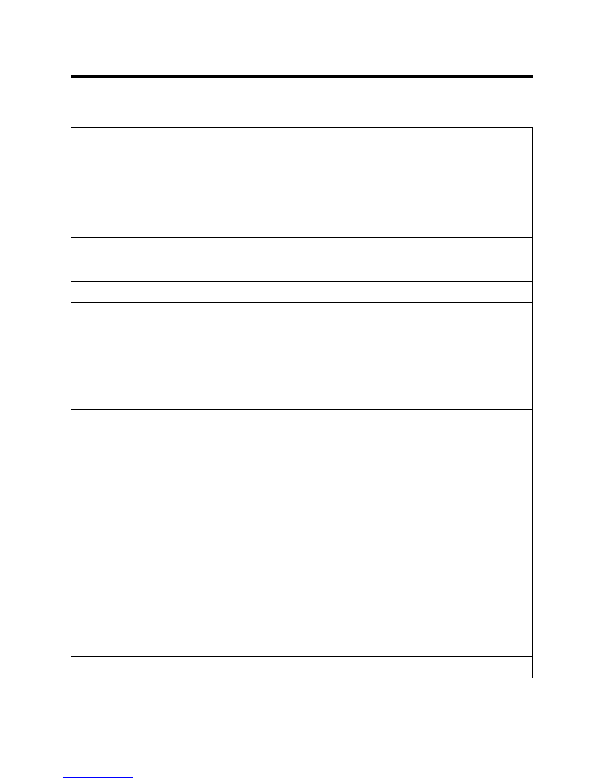
Table 1: SDM-E2 Specifications
Input Power 12 VDC
NOTE: AC Adapter with 100 - 240 VAC, 50/60 Hz,
0.6A input and 12 VDC, 1.2A output provided as
standard.
Environmental Conditions • For Indoor Use Only
• -10° C to 40° C, below 80% Relative Humidity, NonCondensing
Applicable Instrument EAGLE 2
Memory Capacity 64 KB
Maximum Record Size 256 bytes
Maximum Number of
200
Records Saved
Number of Calibration Gas
Cylinders
Up to two calibration gas cylinders per bump test or
calibration at a time
NOTE: If your EAGLE 2 contains more than one non-standard
gas, more than two gas cylinders may be needed to complete a
bump test or calibration.
Standard Accessories • AC Adapter
• USB Flash Drive
• Single Module Data Viewer Software*
• SDM-E2 Docking Station PC Controller
Software*
• Inlet Air Filter
• Instruction Manual
• 10 Foot Long Exhaust Tube
• Two 3 Foot Long Tubes for GAS 1 and GAS 2
Fittings
Not sent with SDM-E2. Download from www.rkiinstruments.com/sdme2.
*
3 • Specifications
• 3 T-Fittings for PC Controlled Configuration
• Check Valve for PC Controlled Configuration
• USB Cable, Type A to Type B
Page 9

About this Manual
The SDM-E2 Docking Station Standalone Configuration Operator’s Manual uses the
following conventions for notes, cautions, and warnings.
NOTE: Describes additional or critical information.
CAUTION: Describes potentia l dam a ge to equ i pm en t.
WARNING: Describes potential danger that can result in injury or death.
Cautions & Safety Information
• Use only polyurethane sample tubing with the SDM-E2. Consult RKI
Instruments, Inc. for other materials.
• Do not subject the SDM-E2 to infrared or intense light. This may cause
communication errors.
• Do not expose the SDM-E2 to water.
• Do not subject the SDM-E2 to any hard impact.
About this Manual • 4
Page 10
Chapter 2: Description
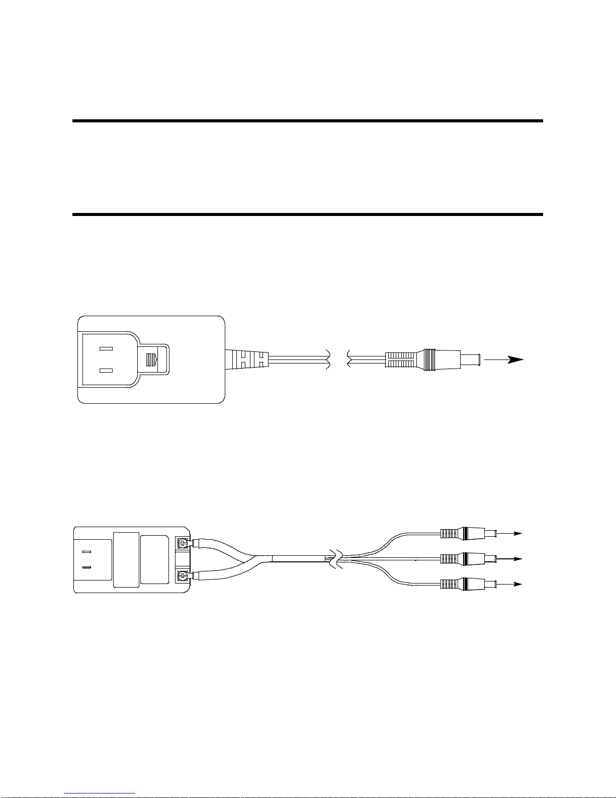
To Power Jack
on SDM-E2
Back Panel
Figure 1: Single-Port AC Adapter
To Power Jack
on SDM-E2
Back Panels
Figure 2: 3-Port AC Adapter
Overview
This section describes the SDM-E2 docking station. It is designed to be used on a
table top and consists of the AC adaptor, Type A to Type B USB cable, air filter, check
valve, sample tubing, instrument panel, back panel, control panel, status LEDs, and 2
USB ports.
AC Adapter
Single-Port AC Adapter
The single-port AC adapter is a wall plug style adapter with a 5 foot cable. The end of
the cable has a plug that connects to the power jack on the SDM-E2’s back panel.
The AC adapter is rated 100 - 240 VAC input, 12 VDC 1.2 A output.
3-Port AC Adapter
The 3-port AC adapter is a wall plug style adapter with three 5-foot cables. The end of
each cable has a plug that connects to the power jack on the SDM-E2’s back panel.
The AC adapter is rated 100 - 240 VAC input, 12 VDC 2.0 A output.
5 • Overview
Page 11
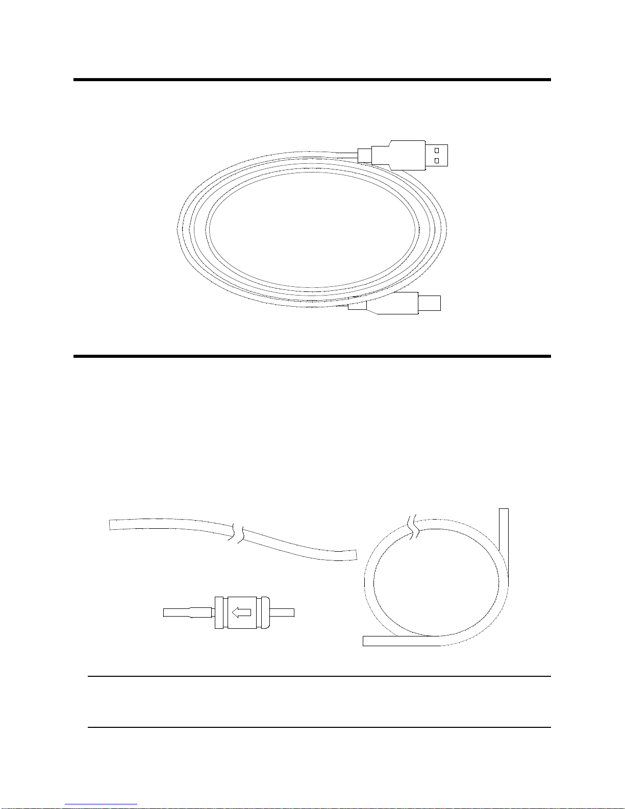
USB Cable
Exhaust Tubing, 10 feet
Calibration GasSample Tubing, 3 feet,
Two TubesIncluded
Particle Filt e r for Air Inlet
Figure 4: Air Filter & Sample Tubing
A Type A to Type B USB cable is provided with the docking station. It is only for use
with the PC Controlled configuration. It is not used in the Standalone configuration.
Figure 3: USB Cable
Air Filter, Sample Tubing, and Check Valve
A cylindrical particle filter with a short length of tubing is supplied with the SDM-E2 for
installation to the AIR fitting on the back panel. The filter keeps particulate
contamination out of the docking station.
Two types of sample tubes are included with the docking station. Two 3 foot lengths
of 3/16 inch ID polyurethane tubing are provided to connect the regulator on a
calibration cylinder to the GAS 1 and GAS 2 fittings on the back panel. In addition, a
10 foot length of 3/16 inch ID polyurethane tubing is provided for connection to the
exhaust fitting on the back panel to allow routing of the exhaust to a location such as
an open window where the exhaust can disperse.
WARNING: Do not use an exhaust tube that is longer than 30 feet. The increased flow
restriction caused by a longer tube may affect gas response and cause
inaccurate calibration and bump test results.
USB Cable • 6
Page 12
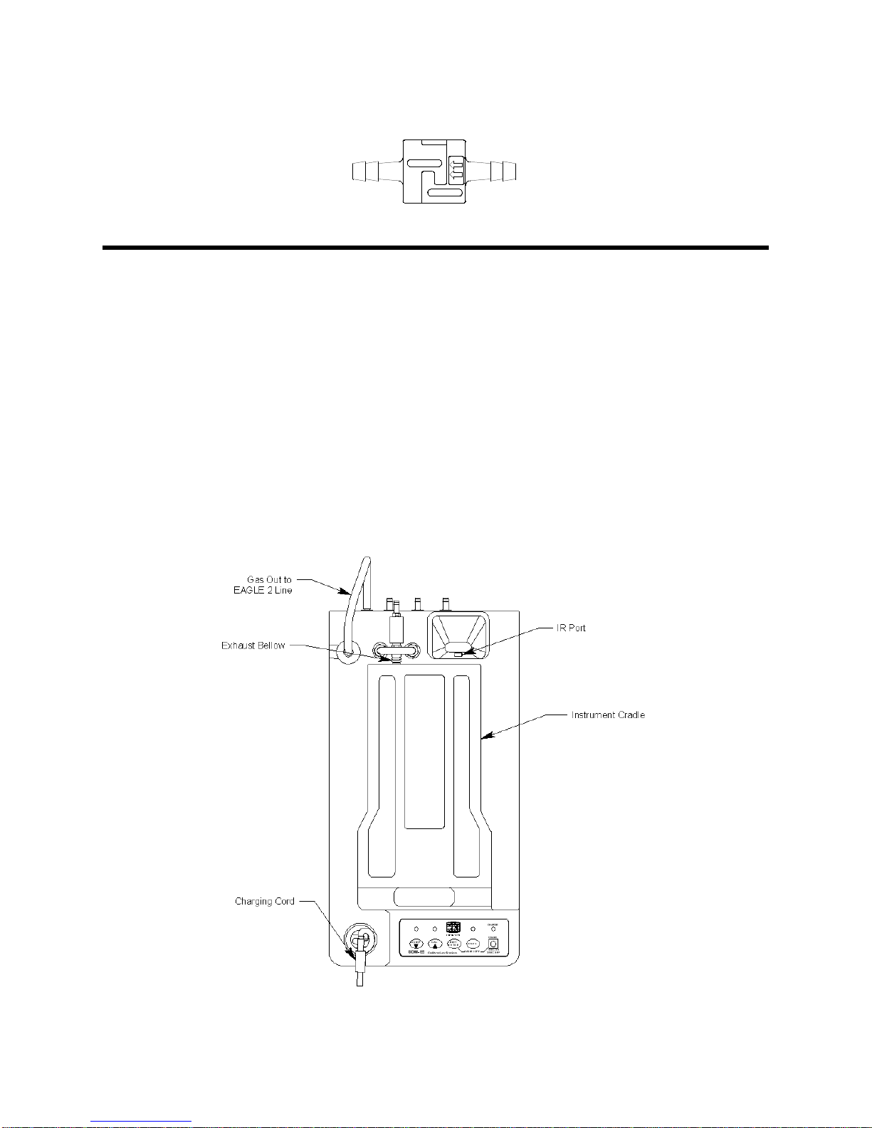
A check valve is included with the SDM-E2 but is not needed for the Standalone
Figure 5: Check Valve
Figure 6: Instrument Panel
configuration. It is used for the PC Controlled configuration.
Instrument Panel
The instrument panel is located on the top of the SDM-E2 and includes the
instrument cradle, the exhaust bellow, the IR port, the charging cord, and a recess for
the fitting at the end of the gas out to EAGLE 2 line. The instrument cradle is a
recessed area on the top of the SDM-E2 that is designed to accept the EAGLE 2.
Insert the EAGLE 2 in the instrument cradle before you perform a bump test,
calibrate, or charge an EAGLE 2. The exhaust bellow is at the back of the instrument
panel and must line up with the exhaust port on the EAGLE 2 when it is in the cradle.
The instrument panel also has a protective metal loop to protect the exhaust bellow
and to prevent the EAGLE 2 from being accidentally dislodged from the cradle.
Follow the instructions in this manual and at the center of the instrument cradle for
installing the EAGLE 2 in the cradle to avoid damaging the exhaust bellow. An
infrared (IR) port at the rear of the panel lines up with the EAGLE 2’s IR port when it is
inserted in the cradle and is used to communicate with the EAGLE 2. The charging
cord and the fitting at the end of the gas out to EAGLE 2 line are stored in the
instrument panel.
7 • Instrument Panel
Page 13
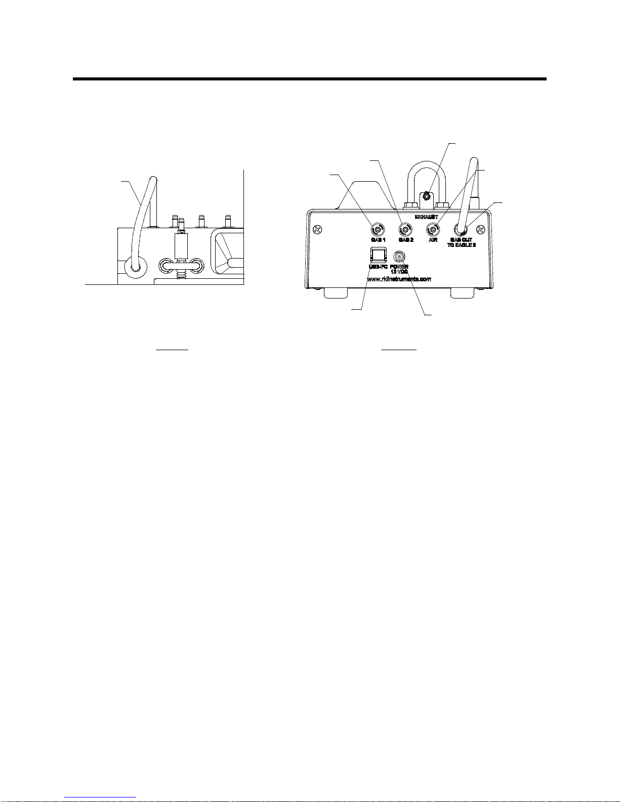
Back Panel
Exhaust Fitting
Air Fitting
Gas Out
to EAGLE
2 Line
Gas Out to
EAGLE 2
Fitting
Power Jack
Back Panel USB Port (Type B),
For Computer Connect ion
Top View Rear View
Gas 1 Fitting
Gas 2 Fitting
Figure 7: Fittings and Connections
The back panel includes the power jack, sample fittings, gas out to EAGLE 2 fitting,
and a USB PC connector.
Power Jack
The power jack is located in the center of the back panel. The plug on the end of the
AC adapter cable mates to it.
Sample Fittings
Five sample fittings are located on the back of the SDM-E2. The gas out to EAGLE 2
fitting is in the upper right corner and has factory installed tubing connected to it. The
gas out to EAGLE 2 fitting directs sample gas to the EAGLE 2 through the gas out to
EAGLE 2 line. The gas out to EAGLE 2 line is stored in the top panel as shown in
Figure 7 above. The AIR fitting is to the left of the gas out to EAGLE 2 fitting and
draws air into the SDM-E2. The two GAS fittings are next to the AIR fitting and are
used to connect the SDM-E2 to calibration gas cylinders. All three fittings accept 3/16
inch ID tubing.
An exhaust fitting is located above the back panel at the back of the exhaust bellow. It
allows routing of the exhausted calibration gas to a convenient location. This fitting
accepts 3/16 inch ID tubing. Even though the exhaust gas can be routed to an area to
be safely dispersed, the docking station should still be installed in a well ventilated
area.
PC Connection
A type B USB connection is located just to the left of the power jack on the SDM-E2’s
back panel. It is only used for the PC Controlled configuration and is not used in the
Standalone configuration.
Back Panel • 8
Page 14
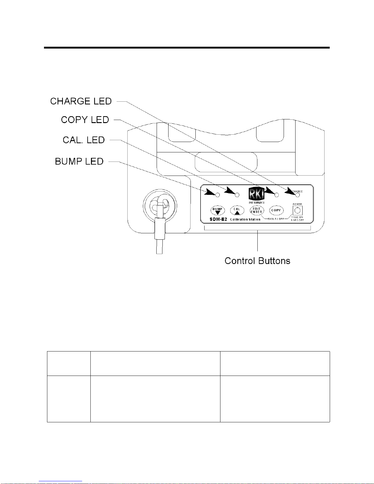
Control Panel
Figure 8: Control Panel
The control panel is used to setup and operate the docking station in the Standalone
configuration. It is located at the front of the docking station. It includes the control
buttons, the control button LEDs, and the CHARGE status LED.
Five control buttons are located on the control panel. From left to right they are BUMP
, CAL , EDIT ENTER, COPY, and POWER. The BUMP , CAL , and COPY
control buttons each have an LED above them that indicates the status of the function
controlled by that button. The CHARGE LED is located above the POWER button
and functions as a pilot LED, a system failure LED, and a charge indication LED.
Table 2: Control Button Functions
Control
Button
Control Button Function(s)
BUMP • Initiates a bump test
• Cancels a bump test
Control Button LED
Function(s)
Indicates status of a bump test
in progress
• Moves down a list of parameters
• Decreases an adjustable
parameter
9 • Control Panel
Page 15

Table 2: Control Button Functions
Control
Button
Control Button Function(s)
CAL • Initiates a calibration
• Cancels a calibration
• Clears data from docking station
memory (when used with COPY
button)
• Moves up a list of parameters
• Increases an adjustable parameter
EDIT
ENTER
• Puts docking station into various
edit modes
• Makes a displayed parameter
editable
• Escapes or cancels an operation
• Turns off connected EAGLE 2
(when used with POWER button)
COPY • Copies data to a USB flash drive.
• Clears data from docking station
memory (when used with CAL
button)
Control Button LED
Function(s)
Indicates status of a calibration
in progress
n/a
• Indicates amount of docking
station memory used
• Indicates status of copying
function
• Indicates the result of a copy
operation
POWER • Turns on the docking station
• Turns off the docking station
• Turns off connected EAGLE 2
(when used with EDIT ENTER
button)
n/a
Control Panel • 10
Page 16
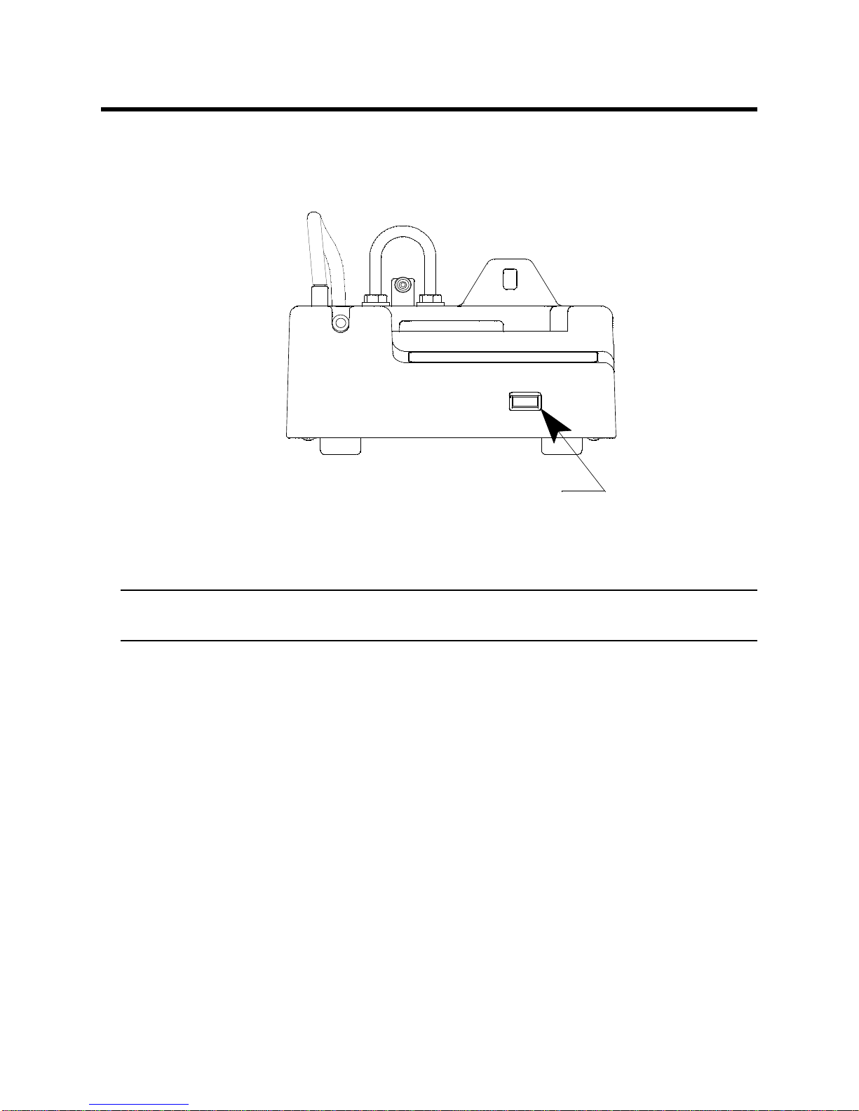
Front Panel
Fr on t P an el US B Po rt (T y p e A),
For Flash Drive
Figure 9: Front Panel
A type A USB port is located on the front of the docking station. This port can be used
to save calibration and bump test data to a USB flash drive. This USB port is for use
only in the Standalone configuration of the SDM-E2.
NOTE: The SDM-E2 does not support connection of a computer to the front
USB port, only a USB flash drive.
11 • Front Panel
Page 17

Chapter 3: Preparing to Use the SDM-E2
Overview
There are four tasks that must be completed before you can begin to use the
SDM-E2: hardware assembly, setting or confirming the bump test and calibration
parameters, connecting calibration gas, and installing the Single Module Data Viewer
Software on your computer. This chapter describes how to assemble the parts that
are shipped with the SDM-E2 and set or view the bump test and calibration
parameters. It also describes how to install the Single Module Data Viewer Software
on a Windows based personal computer.
Hardware Assembly
The hardware assembly consists of connecting the AC adapter, installing the air filter,
and connecting the sample tubing. Perform the following to complete the hardware
assembly:
1. Place the SDM-E2 on a convenient table top near an AC wall socket in a well
ventilated area. A location near a window that can be opened is best so that
the exhaust can be routed to the window.
2. Connect the AC adapter’s wall plug into a wall AC socket.
3. Insert the round plug on the end of the AC adapter’s cable into the power jack
on the back of the SDM-E2.
NOTE: If you have multiple SDM-E2s and are using a 3-port AC adapter, plug
each of the round plugs on the end of the AC adapter into the power
jack on the back of 3 separate SDM-E2s.
4. Install the air filter so that the arrow on the filter that indicates direction of flow
is pointing towards the AIR fitting. Push the open end of the flexible tube that is
on one end of the filter onto the AIR fitting on the back of the SDM-E2.
NOTE: If you have an EAGLE 2 with an IR CO2 sensor in the 0-10,000 ppm or
0-5.00 %vol range, be sure to replace the air filter at the AIR inlet fitting
with the CO2 scrubber when testing an instrument with a CO2 sensor
installed to ensure that the CO2 present in fresh air is scrubbed out.
Remove the black end caps from each end of the scrubber before
installing onto the AIR inlet fitting. Replace the caps when the scrubber
is not in use. See the “Spare Parts List” on page 81 for a scrubber with
a tubing stub.
5. Install the 10 foot long 3/16 inch ID flexible tube that is included with the SDME2 on the exhaust fitting. Route the tube to an area where the exhaust can be
Overview • 12
Page 18
safely dispersed, such as an open window.
CAUTION: The maximum recomme nded le ngth for th e exha ust tube i s 30 feet. Do
not use more than 30 feet of tubing or tubing with an ID of less than
3/16 inch for the exhaust tube or the bump test and calibration
accuracy may be adversely affected. The tube that is shipped with the
SDM-E2 has an ID of 3/16 inch and is 10 feet long.
6. Install the 3 foot long 3/16 inch ID tubes that are included with the SDM-E2 on
the GAS 1 and GAS 2 fittings.
Setting the Operational Parameters
in Edit Mode
Once the hardware has been assembled, use Edit Mode to confirm or adjust bump
test, calibration, and gas inlet parameters before using the SDM-E2.
The bump test parameters define how long fresh air and calibration gas are applied to
an instrument during a bump test. They also define the tolerance used in determining
whether an instrument fails or passes a bump test and whether or not a calibration
automatically takes place if a bump test fails. The calibration parameters define how
long fresh air and calibration gas are applied to an instrument during a calibration.
The gas inlet parameters define what gas inlet fittings (GAS 1, GAS 2, or both) will be
used during bump tests and calibrations.
The bump test and calibration parameters are saved in the SDM-E2’s memory. If a
parameter is changed with one particular EAGLE 2 installed in the SDM-E2, the
change will be in effect for the bump test or calibration of any subsequent EAGLE 2
until the parameter is changed again.
Bump Test & Calibration Parameters
There are four bump test parameters and two calibration parameters. The two
calibration parameters, air sample time and calibration gas sample time, are also
bump test parameters. The parameters are described below. Table 3 below shows
the factory settings for the bump test and calibration parameters. If you wish to use
the factory settings, then you do not need to make any parameter adjustments. If you
wish to confirm or change the parameter settings, follow the instructions below in
“Setting the Bump Test Parameters” on page 18 or “Setting the Calibration
Parameters” on page 20.
Table 3: Bump Test & Calibration Parameter
Parameter
Air Sample Time AIR
Display
Tag
TIME
Available
Choices
• 30 seconds
• 45 seconds
• 60 seconds
Bump Factory
Setting
30 seconds 30 seconds
Cal Factory
Setting
13 • Setting the Operational Parameters in Edit Mode
Page 19

Table 3: Bump Test & Calibration Parameter
Parameter
Calibration Gas
Sample Time
Bump Test Check
To lera nc e
Automatic
Calibration
Display
Tag
GAS
TIME
Available
Choices
•AUTO
• 30 seconds
• 45 seconds
• 60 seconds
• 90 seconds
• 120 seconds
CHECK • ± 10%
•± 20%
•± 30%
•± 40%
•± 50%
• F ± 10%
• F ± 20%
• F ± 30%
• F ± 40%
• F ± 50%
AUTO
CAL
•On
•Off
Bump Factory
Setting
Cal Factory
Setting
30 seconds AUTO
F ± 50% n/a
On n/a
Air Sample Time (AIR TIME)
The air sample time can be set separately for bump testing and calibration. It is the
length of time that the SDM-E2 will draw air through the AIR fitting on the back of the
docking station. Air is drawn during a bump test or calibration before an air adjust
operation and to purge calibration gas from the system after calibration gas has been
drawn through the GAS 1 or GAS 2 fittings on the back of the docking station.
Calibration Gas Sample Time (GAS TIME)
The calibration gas sample time can be set separately for bump testing and
calibration. It is the length of time that the SDM-E2 will draw calibration gas through
the GAS 1 or GAS 2 fittings on the back of the docking station during a bump test. If
the GAS TIME is set to AUTO, the SDM-E2 applies calibration gas for the appropriate
amount of time based on the sensors installed in the EAGLE 2.
Bump Test Check Tolerance (CHECK)
The bump test check tolerance only applies to bump testing. It determines how close
the EAGLE 2 gas reading must be to the calibration gas concentration for each
channel during a bump test in order to pass the bump test. It is defined as a
percentage of the calibration gas concentration.The amount that the EAGLE 2 gas
reading differs from the calibration gas concentration must be equal to or less than
this percentage of the calibration gas concentration. For example, if the tolerance is
set to ±50%, and the %LEL calibration gas concentration is 50% LEL, then the bump
test gas reading for the LEL channel on the EAGLE 2 must be 50 %LEL ± 25 %LEL.
Setting the Operational Parameters in Edit Mode • 14
Page 20
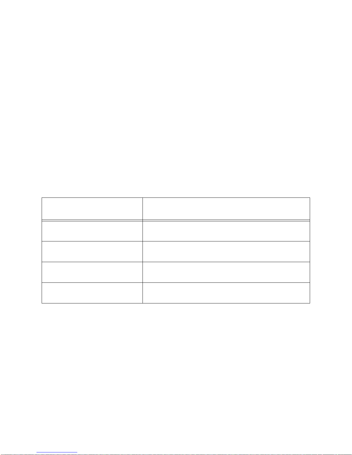
The F±10%, F±20%, F±30%, etc. options represent a fast bump tolerance. If one of
these “F” type tolerances is selected and the gas reading for the sensor(s) being
tested is above the lower tolerance and below the upper tolerance within 10 seconds,
the sensor(s) pass bump testing, the gas application will be stopped, and the test will
move on to the next sensor(s) or to the fresh air purge. If the gas reading on any of
the tested channels is below the lower tolerance or above the upper tolerance within
10 seconds, the gas application will continue for the time period defined by the GAS
TIME bump test parameter, and the pass/fail status of the sensor(s) will be
determined at that point. Using an “F” type tolerance allows calibration gas to be
saved when the sensor respond quickly and accurately.
Consider the following scenario as an example.
• 50% LEL methane used for bump testing the combustible gas channel
• GAS TIME bump test parameter set to 20 seconds
• Tolerance set to F±50%, which means that the acceptable reading range is 25%
LEL - 75% LEL
The table below shows possible readings at 10 seconds and the effect on the gas
application.
Table 4: Example Fast Bump Scenarios
Gas Reading 10 Seconds
Into Fast Bump
Outcome
15% LEL (-70% of 50% LEL) • Gas application continues for the full 20 seconds
• Pass/fail determined at end of 20 seconds
30% LEL (-40% of 50% LEL) • Gas application stops
• Sensor passes bump testing
60% LEL (+20% of 50% LEL) • Gas application stops
• Sensor passes bump testing
80% LEL (+60% of 50% LEL) • Gas application continues for the full 20 seconds
• Pass/fail determined at end of 20 seconds
Automatic Calibration (AUTO CAL)
Automatic calibration only applies to bump testing. It can be set to on or off. If it is set
to on, then the docking station will automatically perform a calibration if a bump test
fails.
Turning on the SDM-E2 with an EAGLE 2
Do the following to turn on the SDM-E2 and establish a connection with an EAGLE 2:
1. Confirm that the AC Adapter is connected to the SDM-E2 and to an AC wall
socket.
2. Press and hold the SDM-E2’s POWER button. The LEDs will turn amber.
3. When the BUMP and CAL LEDs turn off, release the POWER button.
15 • Setting the Operational Parameters in Edit Mode
Page 21
4. The COPY LED will be steadily on or off and the CHARGE LED will be blinking
Ca libra tion S tatio n
COPY
EAGLE 2 OFF
CHARGE
1 SEC ON
3 SE C OFF
CAL
EDIT
ENTER
POWER
SDM-E2
BUMP
A
I
R
Y
E
S
R
A
N
G
E
S
H
I
F
T
P
O
W
E
R
E
N
T
E
R
R
E
S
E
T
D
I
S
P
L
A
Y
A
D
J
U
S
T
N
O
green if the SDM-E2 is operating properly or solid red if there is a system
failure. The amount of free memory in the SDM-E2 will dictate the condition of
the COPY LED (see “Available Memory in the SDM-E2” on page 69).
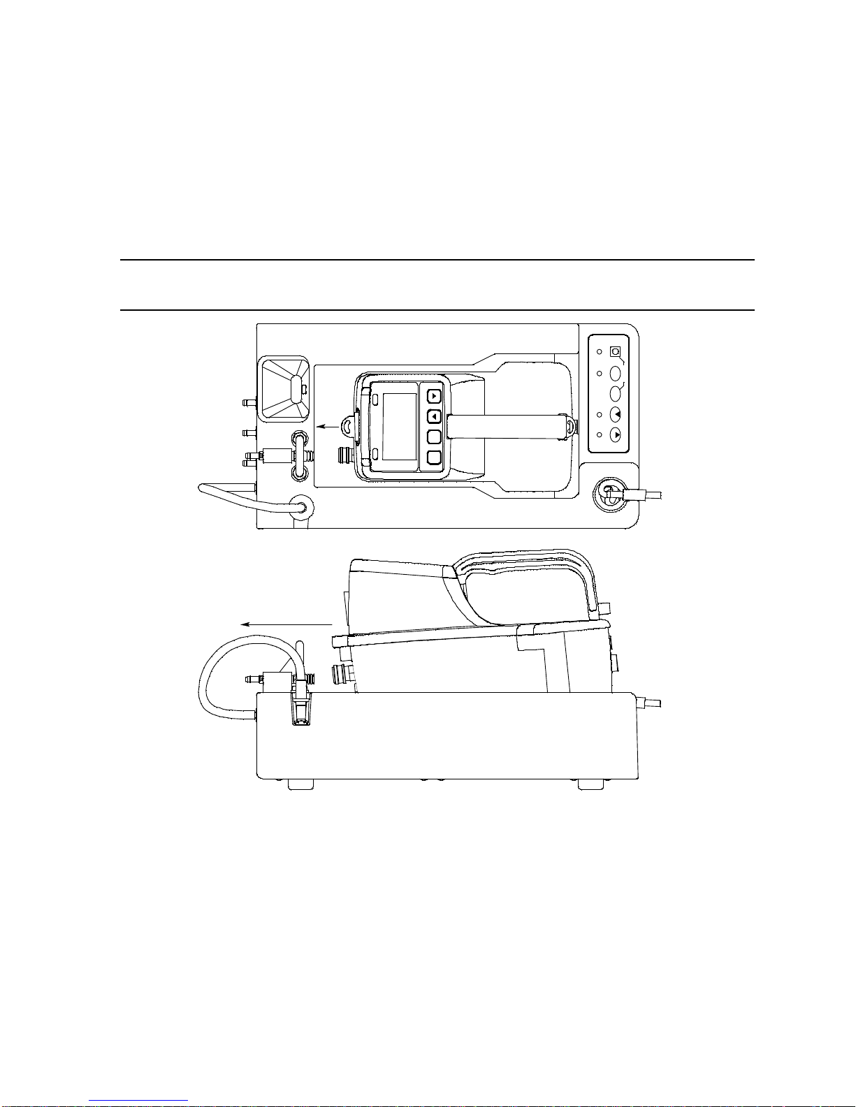
5. Install an EAGLE 2 in the instrument cradle. Set the EAGLE 2 onto the top of
the SDM-E2 and slide the instrument forward until it falls into place as
illustrated.
WARNING: Inserting the EAGLE 2 improperly may damage the exhaust bellow at the
back of the SDM-E2.
Figure 10: Inserting the EAGLE 2
6. If the EAGLE 2 is equipped with NiMH batteries and you wish to charge the
batteries, connect the charging cable at the front of the SDM-E2 to the
charging jack on the back of the instrument. The CHARGE LED will begin
flashing amber. If the batteries are fully charged, the CHARGE LED will
become solid green again after about 5 minutes. Typically a bump test or
calibration will be initiated before this happens. See “Charging an Instrument in
a Docking Station” on page 66 for a complete description of charging the
EAGLE 2.
Setting the Operational Parameters in Edit Mode • 16
Page 22

WARNING: Do not plug the charger cable into a battery pack that contains alkaline
CH4 50%LEL GAS1
OXY 12.0vol% GAS1
H2S 25.0ppm GAS1
CO 50ppm GAS1
---
---
batteries. Do not attempt to charge alkaline batteries.
7. Press and hold the POWER ENTER RESET button on the EAGLE 2 until you
hear a beep, then release it. The EAGLE 2 will begin its power up sequence. If
a successful connection between the EAGLE 2 and the SDM-E2 occurs, the
home screen will appear on the EAGLE 2 display at the end of the startup
sequence.
NOTE: The screen shown above applies to a standard 4-channel EAGLE 2. If
your EAGLE 2 has less than 4 channels, the inactive channels will not
appear in the above screen or in any screens where channels are
displayed. If your EAGLE 2 has a different gas combination, your gas
names and auto calibration values will be different. All screens in this
chapter assume a standard 4-channel EAGLE 2.
17 • Setting the Operational Parameters in Edit Mode
Page 23

Setting the Bump Test Parameters
CH4 50%LEL GAS1
OXY 12.0vol% GAS1
H2S 25.0ppm GAS1
CO 50ppm GAS1
---
---
EDIT MODE
BUMP TEST : BUMP
CALIBRATION : CAL
GAS INLET : EDIT
BUMP TEST PARAMETER
1.AIR TIME: 30sec
2.GAS TIME: AUTO
3.CHECK :F+-50%
4.AUTO CAL: OFF
Do the following to set the bump test parameters after establishing a connection
between an EAGLE 2 and the SDM-E2.
1. Turn on the SDM-E2 with an EAGLE 2 and establish a connection between
them as described above in "Turning on the SDM-E2 with an EAGLE 2". The
EAGLE 2 will display the home screen.
2. Press and hold the EDIT ENTER button for 2 seconds. The EAGLE 2 will
display the Edit Mode screen.
3. Press and release the BUMP button. The EAGLE 2 will display the following
screen with the four bump test parameters and their settings.
Setting the Operational Parameters in Edit Mode • 18
Page 24

4. If you wish to cancel setting the bump test parameters or were just viewing the
BUMP TEST PARAMETER
1.AIR TIME: 30sec <
2.GAS TIME: AUTO
3.CHECK :F+-50%
4.AUTO CAL: OFF
BUMP TEST PARAMETER
1.AIR TIME: 30sec *<
2.GAS TIME: AUTO
3.CHECK :F+-50%
4.AUTO CAL: OFF
parameters to confirm their values, press and release the BUMP button to
return to the home screen.
To continue and change parameters, press and release the EDIT ENTER
button. A cursor will appear to the right of the first bump test parameter. For a
description of the bump test parameters, see “Bump Test & Calibration
Parameters” on page 13.
5. Use the BUMP and CAL buttons to move the cursor up and down until it
is next to the desired parameter. If you move the cursor down past the last
bump test parameter, the instrument will return to the home screen.
6. With the cursor next to the desired parameter, press and release the EDIT
ENTER button. An asterisk (*) will appear on the EAGLE 2 display to the left of
the cursor indicating that the parameter value can be changed. In the example
below, the AIR TIME parameter has been selected for updating.
7. Use the BUMP and CAL buttons to set the parameter to the desired
value, then press and release the EDIT ENTER button. The asterisk next to
the cursor will disappear.
8. Repeat step 5 - step 7 to set any other parameters.
9. When you are done setting the parameters, use the BUMP button to move
the cursor down past AUTO CAL. The screen will indicate that the parameter
changes have been saved and the EAGLE 2 will return to the home screen.
19 • Setting the Operational Parameters in Edit Mode
Page 25

Setting the Calibration Parameters
CH4 50%LEL GAS1
OXY 12.0vol% GAS1
H2S 25.0ppm GAS1
CO 50ppm GAS1
---
---
EDIT MODE
BUMP TEST : BUMP
CALIBRATION : CAL
GAS INLET : EDIT
CAL PARAMETER
1.AIR TIME: 30sec
2.CAL TIME: 60 sec
Do the following to set the calibration parameters after establishing a connection
between an EAGLE 2 and the SDM-E2.
1. Turn on the SDM-E2 with an EAGLE 2 and establish a connection between
them as described above in "Turning on the SDM-E2 with an EAGLE 2". The
EAGLE 2 will display the home screen.
2. Press and hold the EDIT ENTER button for 2 seconds. The EAGLE 2 will
display the Edit Mode screen.
3. Press and release the CAL button. The EAGLE 2 will display the following
screen with the two calibration parameters and their settings.
Setting the Operational Parameters in Edit Mode • 20
Page 26

4. If you wish to cancel setting the calibration parameters or were just viewing the
CAL PARAMETER
1.AIR TIME: 30sec <
2.CAL TIME: 60 sec
CAL PARAMETER
1.AIR TIME: 30sec *<
2.CAL TIME: 60 sec
parameters to confirm their values, press and release the CAL button to
return to the home screen.
To continue, press and release the EDIT ENTER button. A cursor will appear
to the right of the first calibration parameter. For a description of the calibration
parameters, see “Bump Test & Calibration Parameters” on page 13.
5. Use the BUMP and CAL buttons to move the cursor up and down until it
is next to the desired parameter. Do not move the cursor down past the CAL
TIME selection unless you would like to return to the home screen.
6. With the cursor next to the desired parameter, press and release the EDIT
ENTER button. An asterisk (*) will appear on the EAGLE 2 display to the left of
the cursor indicating that the parameter value can be changed. In the example
below, the AIR TIME parameter has been selected for updating.
7. Use the BUMP and CAL buttons to set the parameter to the desired
value, then press and release the EDIT ENTER button. The asterisk next to
the cursor will disappear.
8. Repeat step 5 - step 7 to set any other parameters.
9. When you are done setting the parameters, use the BUMP button to move
the cursor down past CAL TIME. The screen will indicate that the parameter
changes have been saved and the EAGLE 2 will return to the home screen.
21 • Setting the Operational Parameters in Edit Mode
Page 27

Setting the Gas Inlet Parameters
CH4 50%LEL GAS1
OXY 12.0vol% GAS1
H2S 25.0ppm GAS1
CO 50ppm GAS1
---
---
EDIT MODE
BUMP TEST : BUMP
CALIBRATION : CAL
GAS INLET : EDIT
The gas inlet parameters define what gas ports are used during bump testing or
calibration and lets you select the port for each channel in your instrument.
With the exception of the default settings outlined in “Appendix A: Bump Testing and
Calibrating EAGLE 2s with IR Sensors” on page 84, all of the standard 4 sensors
(catalytic LEL, O2, H2S, and CO) are assigned to GAS 1 and special sensors (PID,
TC, IR, and ESM-01) are assigned to GAS 2. When you change a gas inlet
assignment for a particular gas combination (for example, changing the gas inlet for a
high range PID channel to GAS 1 so that a 5-gas cylinder can be utilized), the SDME2 will remember the gas inlet setting for other EAGLE 2s with the same gas
combination. The SDM-E2 will remember the gas inlet setting for 10 EAGLE 2 gas
combinations. When an 11th gas combination is connected, the 1st gas
combination’s gas inlet settings will be discarded.
Do the following to set the gas inlet parameters.
1. Turn on the SDM-E2 with an EAGLE 2 and establish a connection between
them as described above in "Turning on the SDM-E2 with an EAGLE 2". The
EAGLE 2 will display the home screen.
2. Press and hold the EDIT ENTER button for 2 seconds. The EAGLE 2 will
display the Edit Mode screen.
Setting the Operational Parameters in Edit Mode • 22
Page 28

3. Press and release the EDIT ENTER button. The EAGLE 2 will display the
GAS INLET PARAMETER
1.USING : GAS1&GAS2 <
2.ASSIGN : . . .
GAS INLET PARAMETER
1.USING : GAS1&GAS2*<
2.ASSIGN : . . .
following screen with the two gas inlet parameters and a cursor next to the first
parameter. The USING setting will be visible.
4. To change the USING setting, move the cursor next to the USING parameter
with the BUMP or CAL button if necessary and press and release the
EDIT ENTER button. An asterisk will appear to the left of the cursor.
5. Use the BUMP and CAL buttons to scroll through the options: GAS1
ONLY, GAS1&GAS2, and GAS2 ONLY. If GAS1 ONLY is selected, when a
bump test or calibration is performed, only those channels assigned to GAS 1
will be bump tested or calibrated. Similarly, if GAS2 ONLY is selected, when a
bump test or calibration is performed, only those channels assigned to GAS 2
will be bump tested or calibrated. If GAS1&GAS2 is selected, all active
channels will be bump tested or calibrated when one of these operations is
performed.
6. Once you have made your selection, press and release the EDIT ENTER
button. The asterisk will disappear.
23 • Setting the Operational Parameters in Edit Mode
Page 29
7. To edit the gas assignments, move the cursor next to the ASSIGN parameter
CH4 50%LEL GAS1 <
OXY 12.0vol% GAS1
H2S 25.0ppm GAS1
CO 50ppm GAS1
---
---
CH4 50%LEL GAS1 *<
OXY 12.0vol% GAS1
H2S 25.0ppm GAS1
CO 50ppm GAS1
---
---
with the BUMP or CAL button if necessary and press and release EDIT
ENTER. The gas assignment screen will be displayed.
NOTE: See the next section, "Connecting Calibration Gas", for guidelines to
decide whether to assign a channel to GAS 1 or GAS 2.
8. Use the BUMP and CAL buttons to move the cursor next to the channel
you wish to assign to a gas port and press and release EDIT ENTER. An
asterisk will appear to the left of the cursor.
9. Use the BUMP and CAL buttons to display the desired gas port.
10. Press and release the EDIT ENTER button. The asterisk will disappear.
11. Repeat step 8 through step 10 for any additional channels you wish to assign
gas ports to.
12. When you are finished, use the BUMP button to move the cursor down past
the last channel. You will return to the Gas Inlet Parameter Screen.
13. If you are finished making changes in the Gas Inlet Parameter Screen, use the
BUMP button to move the cursor down past the ASSIGN item. The screen
will indicate that changes are being saved and you will return to the home
screen.
Setting the Operational Parameters in Edit Mode • 24
Page 30

Connecting Calibration Gas
The GAS 1 and GAS 2 fittings on the back of the docking station are designed to be
used with a calibration gas cylinder that is fitted with a demand flow regulator. The
AIR fitting may be used with a demand flow regulator and a cylinder of zero
emissions air, but this is not normally necessary since the docking station will
generally be in a fresh air area.
The type of calibration gas cylinder used for the GAS 1 fitting depends on the gas
sensors installed in the EAGLE 2. A 4-gas mix, LEL/Oxygen/CO/H2S, is used for the
GAS 1 fitting if the instrument being used with the docking station is a standard 4-gas
instrument or is a version that has less than 4 standard channels but still has an H2S
channel. If the instrument does not have an H2S channel, then a 3-gas mix, LEL/
Oxygen/CO, is used for the GAS 1 fitting. Although a 4-gas cylinder will work for an
instrument of any standard gas combination, if you have multiple 3- and 4-gas
instruments, you may want to keep a 4-gas cylinder and a 3-gas cylinder to help
preserve the charcoal filter that protects the CO sensor in instruments without an H2S
channel.
The GAS 2 fitting is intended to be used for special sensors (i.e. PID, TC, ESM-01,
etc.). If you have a special sensor installed (i.e. PID, TC, ESM-01, etc.), a special
cylinder for the target gas of that sensor needs to be used for calibration. For
example, if you have a standard 4-gas instrument plus a PID sensor, you will need
both a 4-gas cylinder and a cylinder of 10 ppm isobutylene for low range or 100 ppm
isobutylene for high range calibration. The isobutylene cylinder needs to be
connected to the GAS 2 fitting on the back of the SDM-E2. Similarly, if you have a
standard 4-gas EAGLE 2 plus an ammonia ESM-01 sensor, you will need a cylinder
of 10 ppm ammonia connected to the GAS 2 fitting on the back of the SDM-E2. If you
have a standard 4-gas EAGLE 2 plus a PID sensor and an ammonia ESM-01 sensor,
you will need both an isobutylene calibration cylinder and an ammonia calibration
cylinder. If you have an EAGLE 2 configuration for which a 5-gas cylinder is available
(ie. standard 4 plus SO2 or standard 4 plus high range PID), you may use the 5-gas
cylinder and connect it to the GAS 1 fitting. The SO2 or high range PID channel will
have to be assigned to GAS 1 (see “Setting the Gas Inlet Parameters” on page 22).
For instruments with 2 special sensors, the calibration cylinder for the first special
sensor channel (typically channel 5) needs to be connected to the GAS 2 fitting first.
During bump testing or calibration, the EAGLE 2 screen will prompt you to change the
GAS 2 calibration cylinder when it needs to calibrate the second special sensor
(typically channel 6). If one of the two special sensors has a target gas that’s in a
5-gas cylinder (ie. SO
2
5-gas cylinder is used and the appropriate channel is reassigned to GAS 1.
NOTE: If your EAGLE 2 has an IR sensor installed, see “Appendix A: Bump
Testing and Calibrating EAGLE 2s with IR Sensors” on page 84 for a
brief description of operation specific to IR sensors.
25 • Connecting Calibration Gas
or high range PID), no cylinder change will be required if the
Page 31
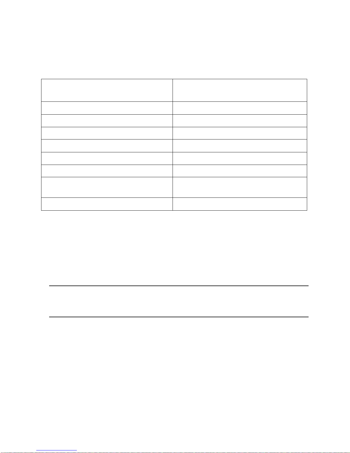
Use Table 5 below as a guide in determining which calibration gas cylinder is
appropriate for your system. See “Spare Parts List” on page 81 for a list of available
cylinder part numbers.
Table 5: Recommended Gas Cylinders for Typical Instrument Types
Typical Instrument Types
Recommended Calibration Gas
Cylinder
3-gas (LEL/Oxy/CO) 3-gas mix with LEL/Oxy/CO
Standard 4-gas (LEL/Oxy/H2S/CO) 4-gas mix with LEL/Oxy/H2S/CO
Standard 4-gas + low range PID 4-gas mix and IBL
Standard 4-gas + high range PID 5-gas mix with LEL/Oxy/CO/H2S/IBL
Standard 4-gas + NH3 4-gas mix and NH3
Standard 4-gas + low range PID + NH3 4-gas mix and IBL and NH3
Standard 4-gas + high range PID + NH3 5-gas mix with LEL/Oxy/CO/H2S/IBL and
NH3
Standard 4-gas + SO2 5-gas mix with LEL/Oxy/CO/H2S/SO2
To connect calibration gas to the SDM-E2, do the following:
1. If the area around the docking station is not considered a fresh air area (an
area free of combustible and toxic gases and of normal oxygen content,
20.9%) install a tube not longer than 10 feet on the filter attached to the AIR
fitting on the back of the docking station and route it to a fresh air area or
connect a cylinder of zero air with a demand flow regulator to the AIR fitting.
2. Install the demand flow regulator on the calibration gas cylinder(s).
WARNING: RKI Instruments, Inc. recommends that you dedicate a regulator for use
with chlorine (Cl2) gas and that you do not use that dedicated regulator for
any other gases, particularly hydrogen sulfide (H2S).
3. Connect the demand flow regulator to the GAS 1 or GAS 2 inlet fitting using
the 3 foot length of 3/16 inch ID sample tubing provided with the docking
station.
For a 3- or 4-gas mix, connect the regulator to the GAS 1 inlet.
For a special calibration cylinder (PID, TC, ESM-01, etc.), connect the
regulator to the GAS 2 inlet.
Connecting Calibration Gas • 26
Page 32

Installing the Single Module Data Viewer
Software
1. Launch Windows®.
2. Exit from all applications and open windows.
3. Go to www.rkiinstruments.com/sdme2.
4. Click on the Download tab.
5. Click the SDM-E2 Standalone Single Module link.
6. A .zip file will begin to download. Select whether you want to open or save the
.zip file.
7. Extract the contents of the .zip file.
8. Double click the setup.exe file.
9. The Single Module Data Viewer InstallShield Wizard comes up to guide you
through installation. Click Next to proceed to the License Agreement window.
10. Read the license agreement and click the agreement acceptance selection
box, then click Next to proceed to the Customer Information window.
11. Enter a user name and organization and select if you want to install the
program for all users on the computer or just for your user account, then click
Next to proceed to the Destination Folder window.
12. The default installation folder (C:\Program Files\Single Module Data Viewer\) is
displayed. If you want to install the software in the default folder continue with
step 8. If you want to install the software in a different location, click Change
and choose a new installation folder now and then continue with step 8.
13. Click Next to proceed to the Ready to Install the Program window.
14. Review the installation settings. If they are OK, click Install and the installation
process will begin. If you want to change installation settings, click Back and
change them to the desired settings.
15. During software installation, the installation program may find newer versions
of Windows files on your computer than those in the downloaded .zip file. If
this happens, the installation software will ask you if you want to keep these
newer files. Click Yes to do so.
16. Follow the on-screen instructions to complete software installation.
27 • Installing the Single Module Data Viewer Software
Page 33

Chapter 4: Operation
Overview
When you have completed the tasks in "Chapter 3: Preparing to Use the SDM-E2",
you are ready to use the SDM-E2 docking station. The SDM-E2 is capable of
performing bump tests and calibrations on the EAGLE 2. It can also charge the
optional rechargeable NiMH batteries in the EAGLE 2. This chapter describes
procedures for using the docking station to bump test, calibrate, and recharge
EAGLE 2s in the standalone configuration of the docking station. It also describes the
information that is saved in the docking station’s memory and how to save that
information to a USB flash drive for use with the Single Module Data Viewer Program.
Bump Testing Instruments with Standard
Sensors
The following instructions apply to EAGLE 2s with one or more of the standard four
sensors (catalytic LEL, O2, CO, and H2S). If your EAGLE 2 includes one or more
special sensors such as a TC, PID, ESM-01, etc., see “Bump Testing an Instrument
with Special Sensors” on page 42 for bump testing instructions.
When a bump test is performed, the SDM-E2 performs a fresh air adjustment on an
EAGLE 2 and then applies calibration gas to the instrument. The docking station then
analyzes the response results based on criteria defined by the bump test check
tolerance parameter and determines if the instrument passed the bump test. The
bump test check tolerance is defined in “Bump Test Check Tolerance (CHECK)” on
page 14. If the automatic calibration parameter is set to ON, then the SDM-E2 will
automatically perform a calibration if the bump test fails.
Do the following to perform a bump test:
1. Confirm that the AC Adapter is connected to the SDM-E2 and to an AC wall
socket.
2. Press and hold the SDM-E2’s POWER button. The LEDs will turn amber.
3. When the BUMP and CAL LEDs turn off, release the POWER button.
4. The COPY LED will be off or on steadily and the CHARGE LED will be blinking
green if the SDM-E2 is operating properly or solid red if there is a system
failure. The amount of free memory in the SDM-E2 will dictate the condition of
the COPY LED (see “Available Memory in the SDM-E2” on page 69).
Overview • 28
Page 34
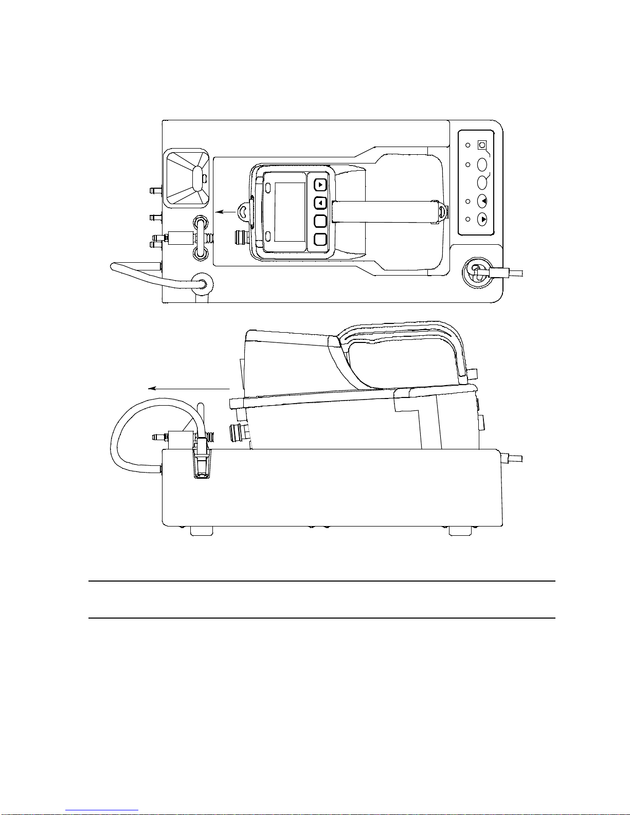
5. Install an EAGLE 2 in the instrument cradle. Set the EAGLE 2 onto the top of
C alibra tion St atio n
COPY
EAGLE 2 OFF
CHARGE
1 SEC ON
3 SEC OFF
CAL
EDIT
ENTER
POWER
SDM-E2
BUMP
A
I
R
Y
E
S
R
A
N
G
E
S
H
I
F
T
P
O
W
E
R
E
N
T
E
R
R
E
S
E
T
D
I
S
P
L
A
Y
A
D
J
U
S
T
N
O
the SDM-E2 and slide the instrument forward until it falls into place as
illustrated below.
Figure 11: Inserting the EAGLE 2
WARNING: Inserting the EAGLE 2 improperly may damage the exhaust bellow at the
back of the SDM-E2.
6. If the EAGLE 2 is equipped with NiMH batteries and you wish to charge the
batteries, connect the charging cable at the front of the SDM-E2 to the
charging jack on the back of the instrument. The CHARGE LED will begin to
flash amber. If the batteries are fully charged, the CHARGE LED will become
solid green again after about 5 minutes. Typically a bump test or calibration will
be initiated before this happens. See “Charging an Instrument in a Docking
Station” on page 66 for a complete description of charging the EAGLE 2.
29 • Bump Testing Instruments with Standard Sensors
Page 35

WARNING: Do not plug the charger cable into a battery pack that contains alkaline
CH4 50%LEL GAS1
OXY 12.0vol% GAS1
H2S 25.0ppm GAS1
CO 50ppm GAS1
---
---
batteries. Do not attempt to charge alkaline batteries.
7. Press and hold the POWER ENTER RESET button on the EAGLE 2 until you
hear a beep, then release it. The EAGLE 2 will begin its power up sequence. If
a successful connection between the EAGLE 2 and the SDM-E2 occurs, the
home screen will display at the end of the start up sequence. If the charge LED
was amber, it will begin to blink green.
NOTE: The screen shown above applies to a standard 4-channel EAGLE 2. If
your EAGLE 2 has less than 4 channels, the inactive channels will not
appear in the above screen or in any screens where channels are
displayed. If your EAGLE 2 has a different gas combination, your gas
names and auto calibration values will be different. All screens in this
section assume a standard 4-channel EAGLE 2.
8. If necessary, confirm that the bump test check tolerance is set to the desired
value. See “Setting the Bump Test Parameters” on page 18.
9. Verify that the appropriate calibration gas cylinder is connected to the GAS 1
and GAS 2 fittings on the back of the SDM-E2. See “Connecting Calibration
Gas” on page 25 for calibration gas cylinder options and calibration gas
connection procedures.
10. Connect the gas out to EAGLE 2 line to the inlet fitting on the EAGLE 2.
Bump Testing Instruments with Standard Sensors • 30
Page 36

11. Press and hold the BUMP button until the BUMP LED turns on (about
CH4 0%LEL Z
OXY 20.9vol% Z
H2S 0.0ppm Z
CO 0ppm Z
---
---
CH4 0%LEL FLOW
OXY 20.9vol% FLOW
H2S 0.0ppm FLOW
CO 0ppm FLOW
---
---
one second) then release it. The bump test begins. During the bump test, the
BUMP LED will flash amber indicating that a bump test is in progress and
the EAGLE 2 display will show the current readings.
If you wish to cancel the bump test, press and hold the BUMP button for at
least one second until CANCEL appears on the screen.
12. If at any point during the bump test the gas flow to the instrument becomes too
low, the bump test will be aborted and the screen will indicate a flow failure.
If a flow failure occurs, confirm all tubing connections are correct and that all
lines are clear.
• To return to the home screen, press and hold the EDIT ENTER button for
about 3 seconds.
• To start another bump test, press and release the BUMP button.
• To perform a calibration, press and release the CAL button.
13. The “Z” to the right of the gas reading indicates that air is being applied to the
instrument for a fresh air adjustment (zero). The SDM-E2 will apply fresh air to
the instrument for the time defined by the AIR TIME bump test parameter.
31 • Bump Testing Instruments with Standard Sensors
Page 37

14. The SDM-E2 will perform a fresh air adjustment on the instrument.
CH4 0%LEL Z P
OXY 20.9vol% Z P
H2S 0.0ppm Z P
CO 0ppm Z P
---
---
CH4 0%LEL Z P
OXY 20.9vol% Z P
H2S 5.0ppm Z F
CO 0ppm Z P
---
---
• If the air adjustment is successful, the SDM-E2 will indicate that all
channels passed with a “P” to the right of the “Z”. The “Z” indicates it is a
fresh air adjustment (zero) result. The SDM-E2 will continue as described
in step 15 below.
• If one or more of the sensors fails the fresh air adjustment, the SDM-E2 will
abort the bump test and will not apply calibration gas. If this happens, the
BUMP LED will flash red indicating a failure and the following screen will
appear indicating which channels passed and failed the fresh air
adjustment with a P (pass) or an F (fail) to the right of the “Z”. The “Z”
indicates it is a fresh air adjustment (zero) result. In the following example,
the H2S channel failed the zero adjustment.
In this case, continue with step 18.
Bump Testing Instruments with Standard Sensors • 32
Page 38

15. The SDM-E2 will apply calibration gas to the instrument for the time defined by
CH4 30%LEL B
OXY 9.0vol% B
H2S 3.0ppm B
CO 15ppm B
---
---
CH4 48%LEL BP
OXY 12.0vol% BP
H2S 3.0ppm BF
CO 47ppm BP
---
---
the GAS TIME bump test parameter. A “B” will appear to the right of the gas
reading to indicate that calibration gas is being applied for a bump test.
At the end of the calibration gas application, the SDM-E2 will determine if the
bump test passed.
16. When the AUTO CAL bump test parameter is set to OFF:
a. The instrument will indicate which channels passed or failed the
bump test with a P (pass) or an F (fail) to the right of the “B” which
indicates it is a bump test result. The bump test gas readings at the
end of the gas application will be displayed.
b. The BUMP LED will continue to flash amber while the docking
station performs a fresh air purge for the time defined by the AIR
TIME bump test parameter. After the purge is complete, if all
channels passed the bump test, the BUMP LED will turn solid
green. If any channels failed the bump test, the BUMP LED will
turn solid red.
c. Continue to step 18.
33 • Bump Testing Instruments with Standard Sensors
Page 39

17. When the AUTO CAL bump test parameter is set to ON:
CH4 48%LEL BP
OXY 12.0vol% BP
H2S 24.0ppm BP
CO 47ppm BP
---
---
• If all channels pass the bump test:
a. The following screen appears indicating all channels passed the
bump test with a “P” to the right of the “B” for each channel:
b. The BUMP LED will continue to flash amber while the docking
station performs a fresh air purge for the time defined by the AIR
TIME bump test parameter. After the purge is complete, The BUMP
LED will turn solid green.
c. Continue to step 18.
• If any channel fails the bump test:
a. A calibration is automatically started and the calibration gas will
continue to be applied.
NOTE: GAS 1 calibration gas will continue to be applied so that the total gas
application time is the time defined by the GAS TIME calibration
parameter. This time includes the time that the instrument was being
bump tested. If the GAS TIME calibration parameter is set to 90
seconds and the GAS TIME bump test parameter is set to 30
seconds, the instrument will sample gas for an additional 60 seconds if
the bump test fails to bring the total exposure time to 90 seconds.
Bump Testing Instruments with Standard Sensors • 34
Page 40

The current gas readings will be displayed along with the bump test
CH4 29%LEL BF C
OXY 18.0vol% BF C
H2S 25.0ppm BP C
CO 45ppm BF C
---
---
CH4 29%LEL BF CF
OXY 18.0vol% BF CF
H2S 25.0ppm BP CP
CO 45ppm BF CP
---
---
results. A “C” will appear next to the channels indicating they are
being calibrated. The BUMP LED will continue to flash amber and
the CAL LED will begin flashing amber to indicate a calibration is
taking place.
b. At the end of the calibration, the instrument displays the calibration
gas readings at the end of the gas application and the results from
both the bump test and the calibration with a P (pass) or an F (fail).
c. The BUMP LED and CAL LED will continue to flash amber
while the docking station performs a fresh air purge for the time
defined by the AIR TIME bump test parameter. After the purge is
complete, the BUMP LED will turn solid red. If all channels
passed the calibration, the CAL LED will turn solid green. If any
channels failed the calibration, the CAL LED will turn solid red.
18. After a successful or failed bump test,
• To perform any other operations:
To perform another bump test, press and hold the BUMP button until the
pump starts. To perform a calibration, press and hold the CAL button
until the pump starts. To return to the home screen, press and hold the
EDIT ENTER button until the home screen appears.
• To turn the EAGLE 2 off:
If the bump test was successful, the instrument will shut off after 15
35 • Bump Testing Instruments with Standard Sensors
Page 41

seconds. If the bump test failed, the instrument will shut off after 10
minutes. If buttons are pressed before the SDM-E2 turns off the
instrument, it will automatically turn it off 10 minutes after the last button
push.
To turn off the instrument before it is automatically turned off, press and
hold the EDIT ENTER and POWER buttons simultaneously for at least one
second and then release them.
CAUTION: When using the EAGLE 2 with the SDM-E2, do not turn off the
instrument using the instrument power button. Use the EDIT ENTER
and POWER buttons on the SDM-E2 to turn off the instrument.
The BUMP or BUMP and CAL LEDs will remain on indicating the
test results. If the same EAGLE 2 is turned on again, the test results will still
be indicated by the BUMP or BUMP and CAL LEDs and on the
EAGLE 2 screen. To clear the BUMP or BUMP and CAL LEDs,
with the EAGLE 2 on, press and release the EDIT ENTER button to return
to the home screen. If a new EAGLE 2 is turned on and connected, the
results displayed by the BUMP or BUMP and CAL LEDs will
automatically be cleared.
19. The results of the bump test or bump test and calibration will be stored in the
SDM-E2’s memory and will be available to copy to a USB flash drive. See
“Copying Calibration and Bump Test Records to a USB Flash Drive” on
page 69 for instructions to copy the saved bump test and calibration records to
a USB flash drive.
20. Disconnect the charging cable, if connected, and the gas out to EAGLE 2 line
from the EAGLE 2.
21. Remove the EAGLE 2 from the SDM-E2.
22. If you wish to bump test additional instruments, repeat step 5 - step 21 above
for each additional instrument.
Calibrating Instruments with Standard
Sensors
The following instructions apply to EAGLE 2s with one or more of the standard four
sensors (catalytic LEL, O2, CO, and H2S). If your EAGLE 2 includes one or more
special sensors such as a TC, PID, ESM-01, etc., see “Calibrating an Instrument with
Special Sensors” on page 56 for calibration instructions.
When a calibration is performed, the docking station performs a fresh air adjustment
on an instrument and then applies calibration gas to the instrument. The docking
station analyzes the calibration results and determines if the instrument passed the
calibration.
Calibrating Instruments with Standard Sensors • 36
Page 42
To perform a calibration on an instrument:
C alibra tion Sta tion
COPY
EAGLE 2 OFF
CHARGE
1 SEC ON
3 SEC OFF
CAL
EDIT
ENTER
POWER
SDM-E2
BUMP
A
I
R
Y
E
S
R
A
N
G
E
S
H
I
F
T
P
O
W
E
R
E
N
T
E
R
R
E
S
E
T
D
I
S
P
L
A
Y
A
D
J
U
S
T
N
O
1. Confirm that the AC Adapter is connected to the SDM-E2 and to an AC wall
socket.
2. Press and hold the SDM-E2’s POWER button. The LEDs will turn amber.
3. When the BUMP and CAL LEDs turn off, release the POWER button.
4. The COPY LED will be off or on steadily and the CHARGE LED will be blinking
green if the SDM-E2 is operating properly or solid red if there is a system
failure. The amount of free memory in the SDM-E2 will dictate the condition of
the COPY LED (see “Available Memory in the SDM-E2” on page 69).
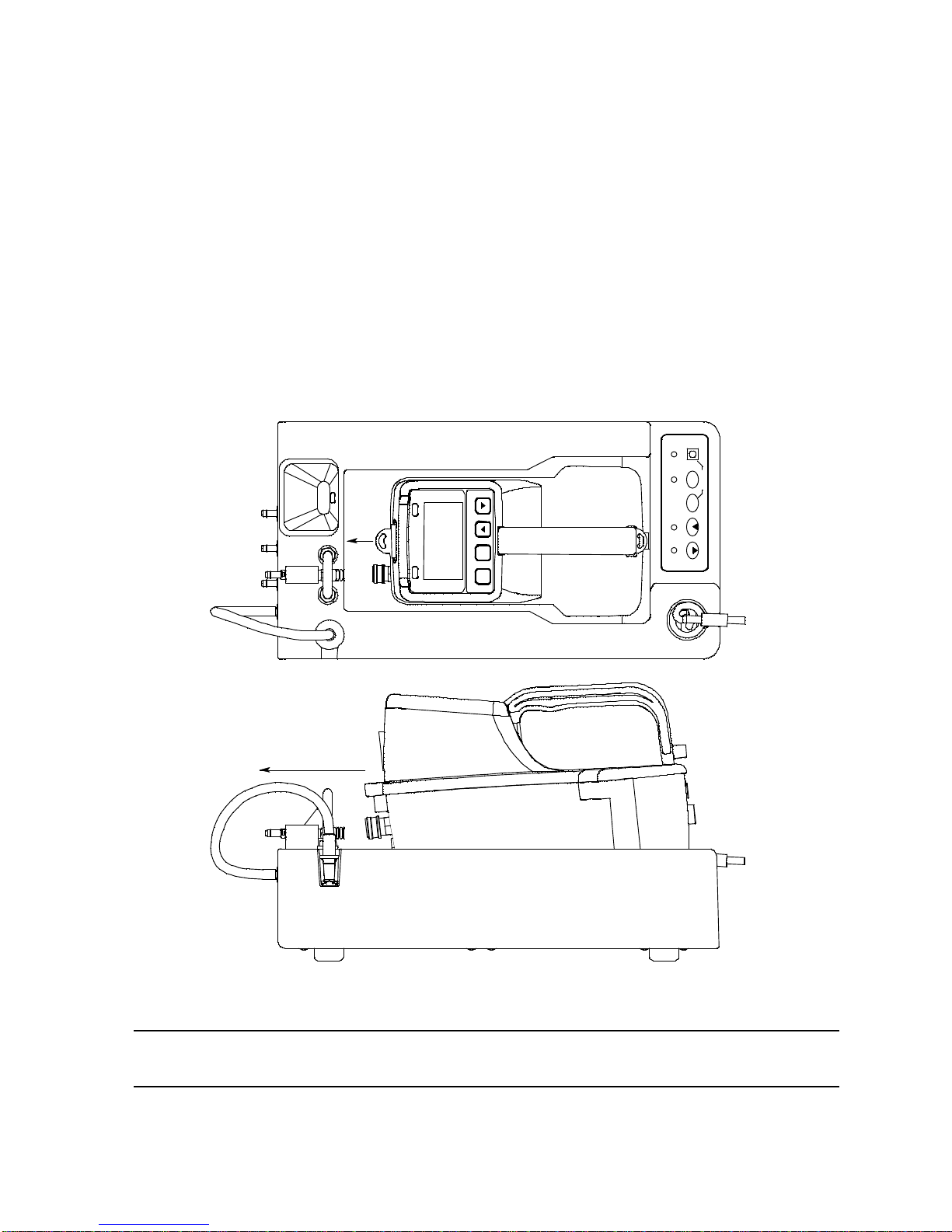
5. Install an EAGLE 2 in the instrument cradle. Set the EAGLE 2 onto the top of
the SDM-E2 and slide the instrument forward until it falls into place as
illustrated below.
Figure 12: Inserting the EAGLE 2
WARNING: Inserting the EAGLE 2 improperly may damage the exhaust bellow at the
back of the SDM-E2.
37 • Calibrating Instruments with Standard Sensors
Page 43
6. If the EAGLE 2 is equipped with NiMH batteries and you wish to charge the
CH4 50%LEL GAS1
OXY 12.0vol% GAS1
H2S 25.0ppm GAS1
CO 50ppm GAS1
---
---
batteries, connect the charging cable at the front of the SDM-E2 to the
charging jack on the back of the instrument. The CHARGE LED will begin to
flash amber. If the batteries are fully charged, the CHARGE LED will become
solid green again after about 5 minutes. Typically a bump test or calibration will
be initiated before this happens. See “Charging an Instrument in a Docking
Station” on page 66 for a complete description of charging the EAGLE 2.
WARNING: Do not plug the charger cable into a battery pack that contains alkaline
batteries. Do not attempt to charge alkaline batteries.
7. Press and hold the POWER ENTER RESET button on the EAGLE 2 until you
hear a beep, then release it. The EAGLE 2 will begin its power up sequence. If
a successful connection between the EAGLE 2 and the SDM-E2 occurs, the
home screen will display at the end of the start up sequence. If the charge LED
was amber, it will begin to blink green.
NOTE: The screen shown above applies to a standard 4-channel EAGLE 2. If
your EAGLE 2 has less than 4 channels, the inactive channels will not
appear in the above screen or in any screens where channels are
displayed. If your EAGLE 2 has a different gas combination, your gas
names and auto calibration values will be different. All screens in this
section assume a standard 4-channel EAGLE 2.
8. Verify that the appropriate calibration gas cylinder is connected to the GAS 1
and GAS 2 fittings on the back of the SDM-E2. See “Connecting Calibration
Gas” on page 25 for calibration gas cylinder options and calibration gas
connection procedures.
9. Connect the gas out to EAGLE 2 line to the inlet fitting on the EAGLE 2.
Calibrating Instruments with Standard Sensors • 38
Page 44

10. Press and hold the CAL button until the CAL LED turns on (about one
CH4 0%LEL Z
OXY 20.9vol% Z
H2S 0.0ppm Z
CO 0ppm Z
---
---
CH4 0%LEL FLOW
OXY 20.9vol% FLOW
H2S 0.0ppm FLOW
CO 0ppm FLOW
---
---
second) then release it. The calibration begins. During the calibration, the
CAL LED will flash amber indicating that a calibration is in progress and the
EAGLE 2 display will show the current readings.
If you wish to cancel the calibration, press and hold the CAL button for at
least one second until CANCEL appears on the screen.
11. If at any point during the calibration the gas flow to the instrument becomes too
low, the calibration will be aborted and the screen will indicate a flow failure.
If a flow failure occurs, confirm all tubing connections are correct and that all
lines are clear.
• To return to the home screen, press and hold the EDIT ENTER button for
about 3 seconds.
• To start another calibration, press and release the CAL button.
• To perform a bump test, press and release the BUMP button.
12. The “Z” to the right of the gas reading indicates that air is being applied to the
instrument for a fresh air adjustment (zero). The SDM-E2 will apply fresh air to
the instrument for the time defined by the AIR TIME calibration parameter.
39 • Calibrating Instruments with Standard Sensors
Page 45

13. The SDM-E2 will perform a fresh air adjustment on the instrument.
CH4 0%LEL Z P
OXY 20.9vol% Z P
H2S 5.0ppm Z P
CO 0ppm Z P
---
---
CH4 0%LEL Z P
OXY 20.9vol% Z P
H2S 25.0ppm Z F
CO 0ppm Z P
---
---
CH4 29%LEL C
OXY 18.0vol% C
H2S 25.0ppm C
CO 45ppm C
---
---
• If the air adjustment is successful, the SDM-E2 will continue as described
in step 14 below.
• If one or more of the sensors fails the fresh air adjustment, the SDM-E2 will
abort the calibration and will not apply calibration gas. If this happens, the
CAL LED will flash red indicating a failure and the following screen will
appear.
In this case continue with step 17.
14. The SDM-E2 will apply calibration gas to the instrument for the time defined by
the GAS TIME calibration parameter.
The “C” indicates calibration gas is being applied.
15. The SDM-E2 will then purge the system with fresh air for the time defined by
the AIR TIME calibration parameter. The calibration results will be displayed
Calibrating Instruments with Standard Sensors • 40
Page 46

with a P (pass) or an F (fail) while the fresh air purge is performed.
CH4 29%LEL CF
OXY 18.0vol% CF
H2S 25.0ppm CP
CO 45ppm CP
---
---
16. Once the fresh air purge is finished, the CAL LED will stop blinking and be
steadily green if the calibration passed or steadily red if the calibration failed.
17. After a successful or failed calibration,
• To perform any other operations:
To perform a bump test, press and hold the BUMP button until the pump
starts. To perform another calibration, press and hold the CAL button
until the pump starts. To return to the home screen, press and hold the
EDIT ENTER button until the home screen appears.
• To turn the EAGLE 2 off:
If the calibration was successful, the instrument will shut off after 15
seconds. If the calibration failed, the instrument will shut off after 10
minutes. If buttons are pressed before the SDM-E2 turns off the
instrument, it will automatically turn it off 10 minutes after the last button
push.
To turn off the instrument before it is automatically turned off, press and
hold the EDIT ENTER and POWER buttons simultaneously for at least one
second and then release them.
CAUTION: When using the EAGLE 2 with the SDM-E2, do not turn off the
instrument using the instrument power button. Use the EDIT ENTER
and POWER buttons on the SDM-E2 to turn off the instrument.
The CAL LED will remain on indicating the test results. If the same
EAGLE 2 is turned on again, the test results will still be indicated by the
CAL LED and on the EAGLE 2 screen. To clear the CAL LED, with
the EAGLE 2 on, press and release the EDIT ENTER button to return to
the home screen. If a new EAGLE 2 is turned on and connected, the
results displayed by the CAL LED will automatically be cleared.
18. The results of the calibration will be stored in the SDM-E2’s memory and will
be available to copy to a USB flash drive. See “Copying Calibration and Bump
Test Records to a USB Flash Drive” on page 69 for instructions to copy the
41 • Calibrating Instruments with Standard Sensors
Page 47

saved bump test and calibration records to a USB flash drive.
19. Disconnect the charger cable, if connected, and the gas out to EAGLE 2 line
from the EAGLE 2.
20. Remove the EAGLE 2 from the SDM-E2.
21. If you wish to calibrate additional instruments, repeat step 5 - step 20 above
for each additional instrument.
Bump Testing an Instrument
with Special Sensors
When a bump test is performed, the SDM-E2 performs a fresh air adjustment on an
EAGLE 2 and then applies calibration gas to the instrument. The docking station then
analyzes the response results based on criteria defined by the bump test check
tolerance parameter and determines if the instrument passed the bump test. The
bump test check tolerance is defined in “Bump Test Check Tolerance (CHECK)” on
page 14. If the automatic calibration parameter is set to on, then the SDM-E2 will
automatically perform a calibration if the bump test fails.
Instruments that have one or more special sensors installed need one or more gas
cylinders to connect to the GAS 2 fitting. Be sure that you have the required
calibration cylinders for your sensors. If you are using a 5-gas cylinder for a special
sensor, be sure that the gas inlet parameters are appropriately assigned as described
in “Setting the Gas Inlet Parameters” on page 22. If your EAGLE 2 has an IR sensor
installed, see “Appendix A: Bump Testing and Calibrating EAGLE 2s with IR Sensors”
on page 84 for a brief description of operation specific to IR sensors.
NOTE: If you wish to calibrate only the standard four sensors or only the
special sensors, be sure that the Gas Inlet Parameters are set
appropriately as described in “Setting the Gas Inlet Parameters” on
page 22.
Do the following to perform a bump test:
1. Confirm that the AC Adapter is connected to the SDM-E2 and to an AC wall
socket.
2. Press and hold the SDM-E2’s POWER button. The LEDs will turn amber.
3. When the BUMP and CAL LEDs turn off, release the POWER button.
4. The COPY LED will be off or on steadily and the CHARGE LED will be blinking
green if the SDM-E2 is operating properly or solid red if there is a system
failure. The amount of free memory in the SDM-E2 will dictate the condition of
the COPY LED (see “Available Memory in the SDM-E2” on page 69).
Bump Testing an Instrument with Special Sensors • 42
Page 48
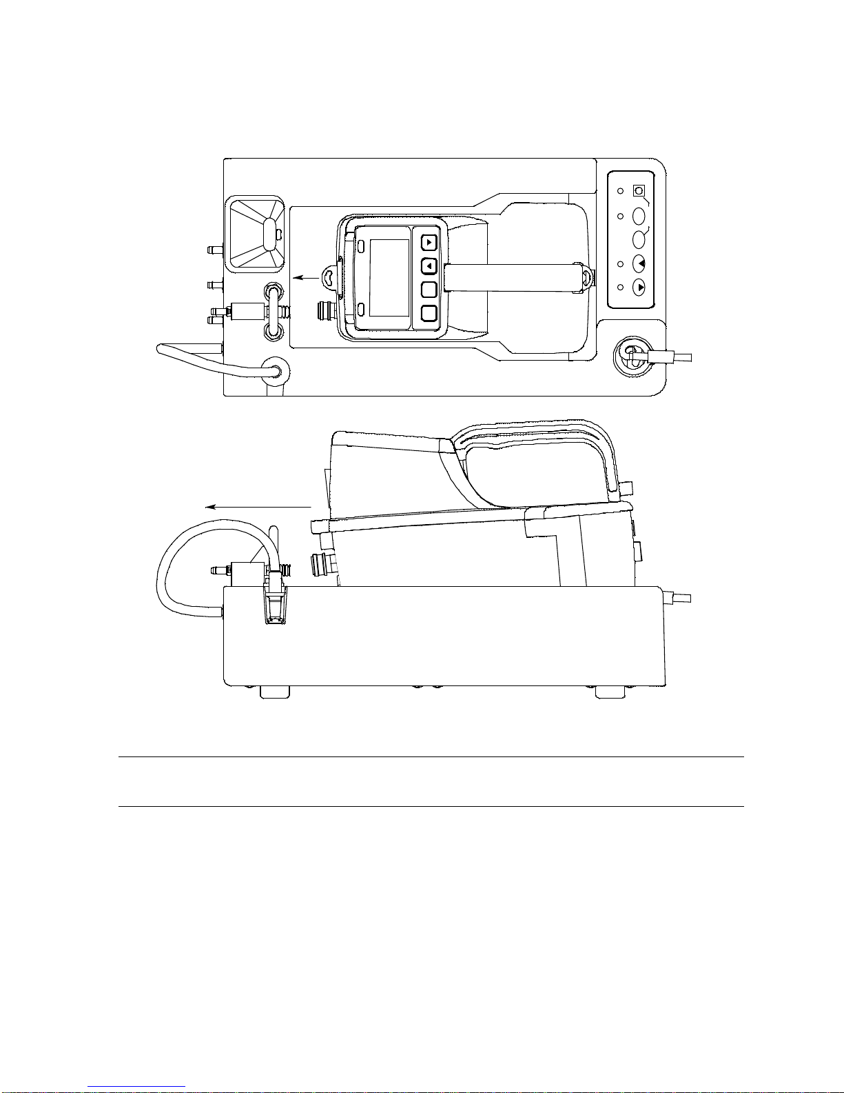
5. Install an EAGLE 2 in the instrument cradle. Set the EAGLE 2 onto the top of
C ali bra tion St atio n
COPY
EAGLE 2 OFF
CHARGE
1 SEC ON
3 SEC OFF
CAL
EDIT
ENTER
POWER
SDM-E2
BUMP
A
I
R
Y
E
S
R
A
N
G
E
S
H
I
F
T
P
O
W
E
R
E
N
T
E
R
R
E
S
E
T
D
I
S
P
L
A
Y
A
D
J
U
S
T
N
O
the SDM-E2 and slide the instrument forward until it falls into place as
illustrated below.
Figure 13: Inserting the EAGLE 2
WARNING: Inserting the EAGLE 2 improperly may damage the exhaust bellow at the
back of the SDM-E2.
6. If the EAGLE 2 is equipped with NiMH batteries and you wish to charge the
batteries, connect the charging cable at the front of the SDM-E2 to the
charging jack on the back of the instrument. The CHARGE LED will begin to
flash amber. If the batteries are fully charged, the CHARGE LED will become
solid green again after about 5 minutes. Typically a bump test or calibration will
be initiated before this happens. See “Charging an Instrument in a Docking
Station” on page 66 for a complete description of charging the EAGLE 2.
43 • Bump Testing an Instrument with Special Sensors
Page 49

WARNING: Do not plug the charger cable into a battery pack that contains alkaline
CH4 50%LEL GAS1
OXY 12.0vol% GAS1
H2S 25.0ppm GAS1
CO 50ppm GAS1
CO2 5000ppm GAS2
NH3 25.0ppm GAS2
batteries. Do not attempt to charge alkaline batteries.
7. Press and hold the POWER ENTER RESET button on the EAGLE 2 until you
hear a beep, then release it. The EAGLE 2 will begin its power up sequence. If
a successful connection between the EAGLE 2 and the SDM-E2 occurs, the
home screen will display at the end of the start up sequence. If the charge LED
was amber, it will begin to blink green. The example screen below shows a
standard 4-channel EAGLE 2 that also includes an IR CO2 sensor in channel 5
and an ESM-01 NH3 sensor in channel 6. The GAS 2 to the right of the CO2
and NH
channels.
channels indicate that the GAS 2 fitting will be used for these
3
NOTE: If your EAGLE 2 has less than 4 standard channels, only one special
sensor, or different special sensors, your gas names and auto
calibration values will be different. All screens in this section assume a
channel setup as shown above.
8. If necessary, confirm that the bump test check tolerance is set to the desired
value. See “Setting the Bump Test Parameters” on page 18.
9. Verify that the appropriate calibration gas cylinder is connected to the GAS 1
and GAS 2 fittings on the back of the SDM-E2. See “Connecting Calibration
Gas” on page 25 for calibration gas cylinder options and calibration gas
connection procedures.
WARNING: RKI Instruments, Inc. recommends that you dedicate a regulator for use
with chlorine (Cl2) gas and that you do not use that dedicated regulator for
any other gases, particularly hydrogen sulfide (H2S).
10. Connect the gas out to EAGLE 2 line to the inlet fitting on the EAGLE 2.
Bump Testing an Instrument with Special Sensors • 44
Page 50
NOTE: If you have an EAGLE 2 with an IR CO2 sensor in the 0-10,000 ppm or
CH4 0%LEL Z
OXY 20.9vol% Z
H2S 0.0ppm Z
CO 0ppm Z
CO2 0ppm Z
NH3 0.0ppm Z
CH4 0%LEL FLOW
OXY 20.9vol% FLOW
H2S 0.0ppm FLOW
CO 0ppm FLOW
CO2 0ppm FLOW
NH3 0.0ppm FLOW
0-5.00 %vol range, be sure to replace the air filter at the AIR inlet fitting
with the CO2 scrubber when testing an instrument with a CO2 sensor
installed to ensure that the CO2 present in fresh air is scrubbed out.
Remove the black end caps from each end of the scrubber before
installing onto the AIR inlet fitting. Replace the caps when the scrubber
is not in use. See the “Spare Parts List” on page 81 for a scrubber with
a tubing stub.
11. Press and hold the BUMP button until the BUMP LED turns on (about
one second) then release it. The bump test begins. During the bump test, the
BUMP LED will flash amber indicating that a bump test is in progress and
the EAGLE 2 display will show the current readings.
If you wish to cancel the bump test, press and hold the BUMP button for at
least one second until CANCEL appears on the screen.
12. If at any point during the bump test the gas flow to the instrument becomes too
low, the bump test will be aborted and the screen will indicate a flow failure.
If a flow failure occurs, confirm all tubing connections are correct and that all
lines are clear.
• To return to the home screen, press and hold the EDIT ENTER button for
45 • Bump Testing an Instrument with Special Sensors
about 3 seconds.
• To start another bump test, press and release the BUMP button.
Page 51

• To perform a calibration, press and release the CAL button.
CH4 0%LEL Z P
OXY 20.9vol% Z P
H2S 0.0ppm Z P
CO 0ppm Z P
CO2 0ppm Z P
NH3 0.0ppm Z P
CH4 0%LEL Z P
OXY 20.9vol% Z P
H2S 0.0ppm Z F
CO 0ppm Z P
CO2 0ppm Z P
NH3 0.0ppm Z P
13. The “Z” to the right of the gas reading indicates that air is being applied to the
instrument for a fresh air adjustment (zero). The SDM-E2 will apply fresh air to
the instrument for the time defined by the AIR TIME bump test parameter.
14. The SDM-E2 will perform a fresh air adjustment on the instrument.
• If the air adjustment is successful, the SDM-E2 will indicate that all
channels passed and continue as described in step 15 below.
• If one or more of the sensors fails the fresh air adjustment, the SDM-E2 will
abort the bump test and will not apply calibration gas. If this happens, the
BUMP LED will flash red indicating a failure and the following screen will
appear indicating which channels passed and failed the fresh air
adjustment with a P (pass) or an F (fail) to the right of the “Z”. The “Z”
indicates it is a fresh air adjustment (zero) result. In the following example,
the H2S channel failed the zero adjustment.
In this case, continue to step 18.
Bump Testing an Instrument with Special Sensors • 46
Page 52

15. The SDM-E2 will apply GAS 1 calibration gas to the instrument for the time
CH4 48%LEL B
OXY 12.0vol% B
H2S 3.0ppm B
CO 47ppm B
CO2 ---------
NH3 ---------
CH4 48%LEL BP
OXY 12.0vol% BP
H2S 3.0ppm BF
CO 47ppm BP
CO2 3500ppm B
NH3 ---------
defined by the GAS TIME bump test parameter. The fifth and sixth
gas reading will be replaced by dashes while the standard 4 sensors are being
bump tested.
At the end of the calibration gas application, the SDM-E2 will determine if the
standard 4 sensors passed the bump test.
16. When the AUTO CAL bump test parameter is set to OFF:
channels’
a. The instrument will indicate which standard 4 channels passed or
failed the bump test with a P (pass) or an F (fail) to the right of the
“B” which indicates it is a bump test result. The bump test gas
readings at the end of the gas application will be displayed. The fifth
channel will then be bump tested with the GAS 2 cylinder.
47 • Bump Testing an Instrument with Special Sensors
Page 53
b. Once the GAS 2 calibration gas has been applied for the
CH4 48%LEL BP
OXY 12.0vol% BP
H2S 3.0ppm BF
CO 47ppm BP
CO2 4500ppm BP
NH3 ---------
CHANGE GAS2
TO NH3
OK : EDIT
CH4 48%LEL BP
OXY 12.0vol% BP
H2S 3.0ppm BF
CO 47ppm BP
CO2 4500ppm BP
NH3 3.0ppm B
appropriate amount of time, the SDM-E2 will determine if the fifth
channel passed the bump test and will indicate a P (pass) or an F
(fail) to the right of the “B” which indicates it is a bump test result.
NOTE: If your instrument has only one special sensor, continue to step18.
c. If your instrument has more than one special sensor, as in this
example, you will need to change the GAS 2 cylinder in order for the
bump test to continue. In the example below, the EAGLE 2’s second
special sensor is an ESM-01 for NH3.The EAGLE 2 screen will
appear as shown below:
d. Once you have changed the GAS 2 cylinder to the appropriate gas,
press and release the EDIT ENTER button on the SDM-E2. The
bump test will continue.
Bump Testing an Instrument with Special Sensors • 48
Page 54

e. Once the GAS 2 calibration gas has been applied for the
CH4 48%LEL BP
OXY 12.0vol% BP
H2S 3.0ppm BF
CO 47ppm BP
CO2 4500ppm BP
NH3 3.0ppm BF
CH4 48%LEL BP
OXY 12.0vol% BP
H2S 23.0ppm BP
CO 47ppm BP
CO2 3500ppm B
NH3 ---------
appropriate amount of time, the SDM-E2 will determine if the sixth
channel passed the bump test and will indicate a P (pass) or an F
(fail) to the right of the “B” which indicates it is a bump test result.
f. The BUMP LED will continue to flash amber while the docking
station performs a fresh air purge for the time defined by the AIR
TIME bump test parameter. After the purge is complete, if all
channels passed the bump test, the BUMP LED will turn solid
green. If any channels failed the bump test, the BUMP LED will
turn solid red.
g. Continue to step 18.
17. When the AUTO CAL bump test parameter is set to ON:
• If all standard 4 channels pass the bump test:
a. The following screen appears indicating all standard 4 channels
passed the bump test and a bump test will begin on the fifth
channel.
49 • Bump Testing an Instrument with Special Sensors
Page 55
b. GAS 2 calibration gas will be applied to the fifth sensor and the
CH4 48%LEL BP
OXY 12.0vol% BP
H2S 23.0ppm BP
CO 47ppm BP
CO2 4500ppm BP
NH3 ---------
CHANGE GAS2
TO NH3
OK : EDIT
CH4 48%LEL BP
OXY 12.0vol% BP
H2S 23.0ppm BP
CO 47ppm BP
CO2 4500ppm BP
NH3 3.0ppm B
SDM-E2 will determine if it passed bump testing. If it passed, the
following screen will appear:
NOTE: If your instrument has only one special sensor, continue to step18.
c. If your instrument has more than one special sensor, as in this
example, you will need to change the GAS 2 cylinder in order for the
bump test to continue. In the example below, the EAGLE 2’s second
special sensor is an ESM-01 for NH3.The EAGLE 2 screen will
appear as shown below:
d. Once you have changed the GAS 2 cylinder to the appropriate gas,
press and release the EDIT ENTER button on the SDM-E2. The
bump test will continue.
Bump Testing an Instrument with Special Sensors • 50
Page 56

e. Once the GAS 2 calibration gas has been applied for the
CH4 48%LEL BP
OXY 12.0vol% BP
H2S 23.0ppm BP
CO 47ppm BP
CO2 4500ppm BP
NH3 23.0ppm BP
CH4 29%LEL BF C
OXY 18.0vol% BF C
H2S 25.0ppm BP C
CO 45ppm BF C
CO2 ---------
NH3 ---------
appropriate amount of time, the SDM-E2 will determine if the sixth
channel passed the bump test and will indicate a P (pass) or an F
(fail) to the right of the “B” which indicates it is a bump test result. If it
passed, the following screen will appear.
f. The BUMP LED will continue to flash amber while the docking
station performs a fresh air purge for the time defined by the AIR
TIME bump test parameter. After the purge is complete, The BUMP
LED will turn solid green.
g. Continue to step 18.
• If any of the standard four channels fails the bump test:
a. A calibration is automatically started on the standard four channels
and the GAS 1 calibration gas will continue to be applied. The
current gas readings will be displayed along with the bump test
results. A “C” will appear next to the channels indicating they are
being calibrated.
51 • Bump Testing an Instrument with Special Sensors
Page 57
NOTE: GAS 1 calibration gas will continue to be applied so that the total gas
CH4 29%LEL BF CF
OXY 18.0vol% BF CF
H2S 25.0ppm BP CP
CO 45ppm BF CP
CO2 3500ppm B
NH3 ---------
CH4 29%LEL BF CF
OXY 18.0vol% BF CF
H2S 25.0ppm BP CP
CO 45ppm BF CP
CO2 3500ppm BF C
NH3 ---------
application time is the time defined by the GAS TIME calibration
parameter. This time includes the time that the instrument was being
bump tested. If the GAS TIME calibration parameter is set to 90
seconds and the GAS TIME bump test parameter is set to 30
seconds, the instrument will sample gas for an additional 60 seconds if
the bump test fails to bring the total exposure time to 90 seconds.
The gas reading for the fifth and sixth channels will be replaced by
dashes while the standard 4 sensors are calibrated. The BUMP
LED will continue to flash amber and the CAL LED will begin
flashing amber to indicate a calibration is taking place.
b. At the end of the calibration, the instrument displays the calibration
gas readings and the results from both the bump test and the
calibration for the standard 4 sensors with a P (pass) or an F (fail). A
bump test then begins on the fifth channel.
c. GAS 2 calibration gas will be applied to the fifth channel and the
SDM-E2 will determine if it passes bump testing. If it does not pass,
a calibration will automatically begin on that channel. If it does pass,
the bump test will continue as described in step e.
Bump Testing an Instrument with Special Sensors • 52
Page 58
d. Once the calibration is complete, the screen will indicate whether
CH4 29%LEL BF CF
OXY 18.0vol% BF CF
H2S 25.0ppm BP CP
CO 45ppm BF CP
CO2 4500ppm BF CP
NH3 ---------
CHANGE GAS2
TO NH3
OK : EDIT
CH4 29%LEL BF CF
OXY 18.0vol% BF CF
H2S 25.0ppm BP CP
CO 45ppm BF CP
CO2 4500ppm BF CP
NH3 3.0ppm B
the fifth channel calibration passed or failed.
NOTE: If your instrument has only one special sensor, continue to stepi.
e. If your instrument has more than one special sensor, as in this
example, you will need to change the GAS 2 cylinder in order for the
bump test to continue. In the example below, the EAGLE 2’s second
special sensor is an ESM-01 for NH3. The EAGLE 2 screen will
appear as shown below:
f. Once you have changed the GAS 2 cylinder to the appropriate gas,
press and release the EDIT ENTER button on the SDM-E2. The
bump test will continue.
53 • Bump Testing an Instrument with Special Sensors
Page 59

g. GAS 2 calibration gas will be applied to the sixth channel and the
CH4 29%LEL BF CF
OXY 18.0vol% BF CF
H2S 25.0ppm BP CP
CO 45ppm BF CP
CO2 4500ppm BF CP
NH3 3.0ppm BF C
CH4 29%LEL BF CF
OXY 18.0vol% BF CF
H2S 25.0ppm BP CP
CO 45ppm BF CP
CO2 3500ppm BF CP
NH3 21.0ppm BF CP
SDM-E2 will determine if it passes bump testing. If it does not pass,
a calibration will automatically begin on that channel. If it does pass,
the bump test will continue as described in step i.
h. Once the calibration is complete, the screen will indicate whether
the sixth channel calibration passed or failed.
i. The BUMP LED and CAL LED will continue to flash amber
while the docking station performs a fresh air purge for the time
defined by the AIR TIME bump test parameter. After the purge is
complete, the BUMP LED will turn solid red. If all channels
passed the calibration, the CAL LED will turn solid green. If any
channels failed the calibration, the CAL LED will turn solid red.
18. After a successful or failed bump test,
• To perform any other operations:
To perform another bump test, press and hold the BUMP button until the
pump starts. To perform a calibration, press and hold the CAL button
until the pump starts. To return to the home screen, press and hold the
EDIT ENTER button until the home screen appears.
• To turn the EAGLE 2 off:
If the bump test was successful, the instrument will shut off after 15
seconds. If the bump test failed, the instrument will shut off after 10
minutes. If buttons are pressed before the SDM-E2 turns off the
Bump Testing an Instrument with Special Sensors • 54
Page 60

instrument, it will automatically turn it off 10 minutes after the last button
push.
To turn off the instrument before it is automatically turned off, press and
hold the EDIT ENTER and POWER buttons simultaneously for at least one
second and then release them.
CAUTION: When using the EAGLE 2 with the SDM-E2, do not turn off the
instrument using the instrument power button. Use the EDIT ENTER
and POWER buttons on the SDM-E2 to turn off the instrument.
The BUMP or BUMP and CAL LEDs will remain on indicating the
test results. If the same EAGLE 2 is turned on again, the test results will still
be indicated by the BUMP or BUMP and CAL LEDs and on the
EAGLE 2 screen. To clear the BUMP or BUMP and CAL LEDs,
with the EAGLE 2 on, press and release the EDIT ENTER button to return
to the home screen. If a new EAGLE 2 is turned on and connected, the
results displayed by the BUMP or BUMP and CAL LEDs will
automatically be cleared.
19. The results of the bump test or bump test and calibration will be stored in the
SDM-E2’s memory and will be available to copy to a USB flash drive. See
“Copying Calibration and Bump Test Records to a USB Flash Drive” on
page 69 for instructions to copy the saved bump test and calibration records to
a USB flash drive.
20. Disconnect the charging cable, if connected, and the gas out to EAGLE 2 line
from the EAGLE 2.
21. Remove the EAGLE 2 from the SDM-E2.
22. If you wish to bump test additional instruments, repeat step 5 - step 21 above
for each additional instrument.
55 • Bump Testing an Instrument with Special Sensors
Page 61

Calibrating an Instrument
with Special Sensors
When a calibration is performed, the docking station performs a fresh air adjustment
on an instrument and then applies calibration gas to the instrument. The docking
station analyzes the calibration results and determines if the instrument passed the
calibration.
Instruments that have one or more special sensors installed need one or more gas
cylinders to connect to the GAS 2 fitting. Be sure that you have the required
calibration cylinders for your sensors. If you are using a 5-gas cylinder for a special
sensor, be sure that the gas inlet parameters are appropriately assigned as described
in “Setting the Gas Inlet Parameters” on page 22. If your EAGLE 2 has an IR sensor
installed, see “Appendix A: Bump Testing and Calibrating EAGLE 2s with IR Sensors”
on page 84 for a brief description of operation specific to IR sensors.
NOTE: If you wish to calibrate only the standard four sensors or only the
special sensors, be sure that the Gas Inlet Parameters are set
appropriately as described in “Setting the Gas Inlet Parameters” on
page 22.
To perform a calibration on an instrument:
1. Confirm that the AC Adapter is connected to the SDM-E2 and to an AC wall
socket.
2. Press and hold the SDM-E2’s POWER button. The LEDs will turn amber.
3. When the BUMP and CAL LEDs turn off, release the POWER button.
4. The COPY LED will be off or on steadily and the CHARGE LED will be blinking
green if the SDM-E2 is operating properly or solid red if there is a system
failure. The amount of free memory in the SDM-E2 will dictate the condition of
the COPY LED (see “Available Memory in the SDM-E2” on page 69).
Calibrating an Instrument with Special Sensors • 56
Page 62
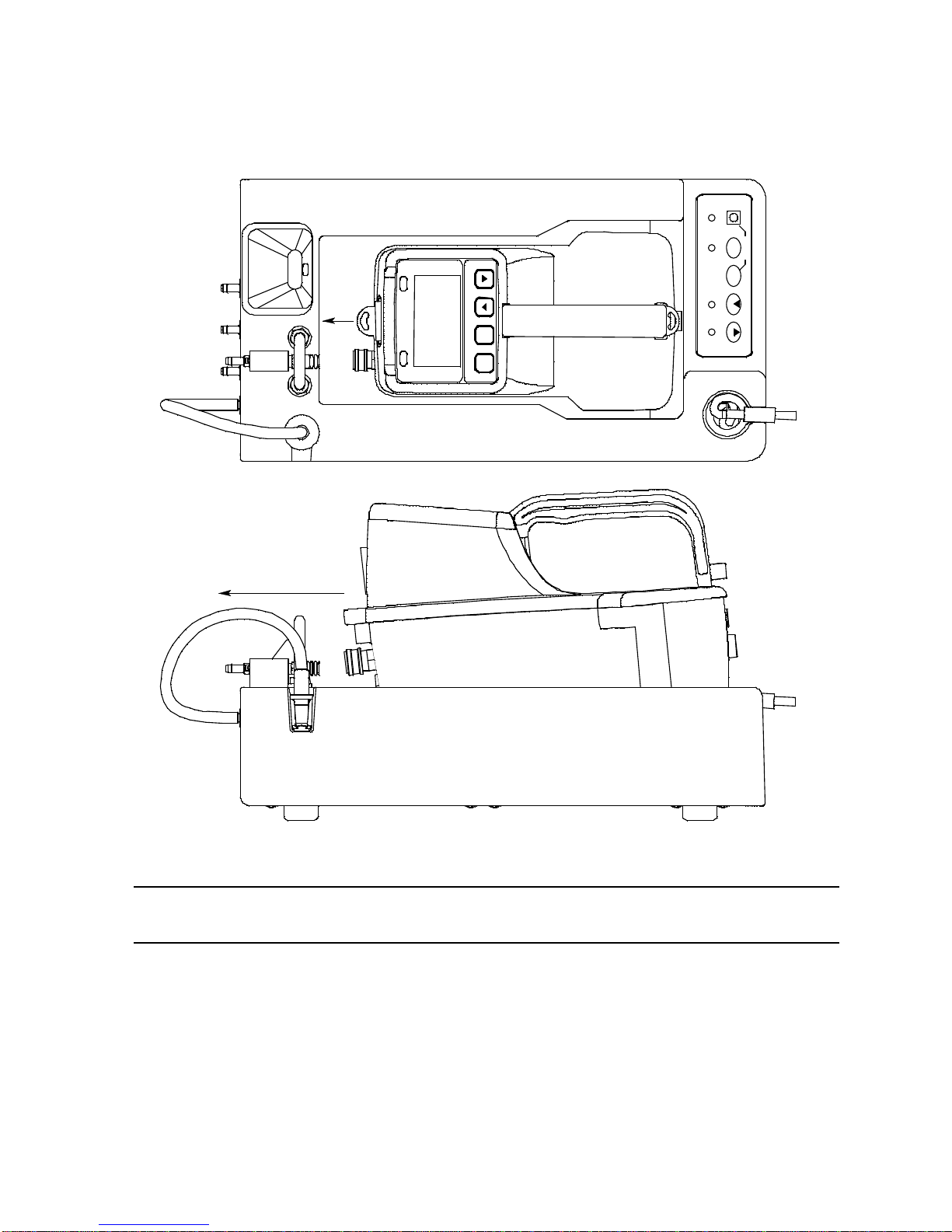
5. Install an EAGLE 2 in the instrument cradle. Set the EAGLE 2 onto the top of
Calib rat i on Stati on
COPY
EAGLE 2 OFF
CHARGE
1 SEC ON
3 SEC OFF
CAL
EDIT
ENTER
POWER
SDM-E2
BUMP
A
I
R
Y
E
S
R
A
N
G
E
S
H
I
F
T
P
O
W
E
R
E
N
T
E
R
R
E
S
E
T
D
I
S
P
L
A
Y
A
D
J
U
S
T
N
O
the SDM-E2 and slide the instrument forward until it falls into place as
illustrated below.
Figure 14: Inserting the EAGLE 2
WARNING: Inserting the EAGLE 2 improperly may damage the exhaust bellow at the
back of the SDM-E2.
6. If the EAGLE 2 is equipped with NiMH batteries and you wish to charge the
batteries, connect the charging cable at the front of the SDM-E2 to the
charging jack on the back of the instrument. The CHARGE LED will begin to
flash amber. If the batteries are fully charged, the CHARGE LED will become
solid green again after about 5 minutes. Typically a bump test or calibration will
be initiated before this happens. See “Charging an Instrument in a Docking
Station” on page 66 for a complete description of charging the EAGLE 2.
57 • Calibrating an Instrument with Special Sensors
Page 63

WARNING: Do not plug the charger cable into a battery pack that contains alkaline
CH4 50%LEL GAS1
OXY 12.0vol% GAS1
H2S 25.0ppm GAS1
CO 50ppm GAS1
CO2 5000ppm GAS2
NH3 25.0ppm GAS2
batteries. Do not attempt to charge alkaline batteries.
7. Press and hold the POWER ENTER RESET button on the EAGLE 2 until you
hear a beep, then release it. The EAGLE 2 will begin its power up sequence. If
a successful connection between the EAGLE 2 and the SDM-E2 occurs, the
home screen will display at the end of the start up sequence. If the charge LED
was amber, it will begin to blink green. The example screen below shows a
standard 4-channel EAGLE 2 that also includes an IR CO2 sensor in channel 5
and an ESM-01 NH3 sensor in channel 6. The GAS 2 to the right of the CO2
and NH
channels.
channels indicate that the GAS 2 fitting will be used for these
3
NOTE: If your EAGLE 2 has less than 4 standard channels, only one special
sensor, or different special sensors, your gas names and auto
calibration values will be different. All screens in this section assume a
channel setup as shown above.
8. Verify that the appropriate calibration gas cylinder is connected to the GAS 1
and GAS 2 fittings on the back of the SDM-E2. See “Connecting Calibration
Gas” on page 25 for calibration gas cylinder options and calibration gas
connection procedures.
WARNING: RKI Instruments, Inc. recommends that you dedicate a regulator for use
with chlorine (Cl2) gas and that you do not use that dedicated regulator for
any other gases, particularly hydrogen sulfide (H2S).
Calibrating an Instrument with Special Sensors • 58
Page 64

9. Connect the gas out to EAGLE 2 line to the inlet fitting on the EAGLE 2.
CH4 0%LEL Z
OXY 20.9vol% Z
H2S 0.0ppm Z
CO 0ppm Z
CO2 0ppm Z
NH3 0.0ppm Z
CH4 0%LEL FLOW
OXY 20.9vol% FLOW
H2S 0.0ppm FLOW
CO 0ppm FLOW
CO2 0ppm FLOW
NH3 0.0ppm FLOW
NOTE: If you have an EAGLE 2 with an IR CO2 sensor in the 0-10,000 ppm or
0-5.00 %vol range, be sure to replace the air filter at the AIR inlet fitting
with the CO2 scrubber when testing an instrument with a CO2 sensor
installed to ensure that the CO2 present in fresh air is scrubbed out.
Remove the black end caps from each end of the scrubber before
installing onto the AIR inlet fitting. Replace the caps when the scrubber
is not in use. See the “Spare Parts List” on page 81 for a scrubber with
a tubing stub.
10. Press and hold the CAL button until the CAL LED turns on (about one
second) then release it. The calibration begins. During the calibration, the
CAL LED will flash amber indicating that a calibration is in progress and the
EAGLE 2 display will show the current readings.
If you wish to cancel the calibration, press and hold the CAL button for at
least one second until CANCEL appears on the screen.
11. If at any point during the bump test the gas flow to the instrument becomes too
low, the bump test will be aborted and the screen will indicate a flow failure.
If a flow failure occurs, confirm all tubing connections are correct and that all
lines are clear.
• To return to the home screen, press and hold the EDIT ENTER button for
about 3 seconds.
59 • Calibrating an Instrument with Special Sensors
Page 65

• To start another calibration, press and release the CAL button.
CH4 0%LEL Z P
OXY 20.9vol% Z P
H2S 0.0ppm Z P
CO 0ppm Z P
CO2 0ppm Z P
NH3 0.0ppm Z P
CH4 0%LEL Z P
OXY 20.9vol% Z P
H2S 0.0ppm Z F
CO 0ppm Z P
CO2 0ppm Z P
NH3 0.0ppm Z P
CH4 29%LEL C
OXY 18.0vol% C
H2S 25.0ppm C
CO 45ppm C
CO2 ---------
NH3 ---------
• To perform a bump test, press and release the BUMP button.
12. The “Z” to the right of the gas reading indicates that air is being applied to the
instrument for a fresh air adjustment (zero). The SDM-E2 will apply fresh air to
the instrument for the time defined by the AIR TIME calibration parameter.
13. The SDM-E2 will perform a fresh air adjustment on the instrument.
• If the air adjustment is successful, the SDM-E2 will continue as described
in step 14 below.
• If one or more of the sensors fails the fresh air adjustment, the SDM-E2 will
abort the calibration and will not apply calibration gas. If this happens, the
CAL LED will flash red indicating a failure and the following screen will
appear.
In this case, continue with step 22.
14. The SDM-E2 will apply GAS 1 calibration gas to the instrument for the time
defined by the GAS TIME calibration parameter and first calibrate the standard
four sensors.
The “C” indicates calibration gas is being applied. The gas readings for the fifth
and sixth channels will be replaced by dashes since they are not being
calibrated yet.
Calibrating an Instrument with Special Sensors • 60
Page 66
15. The calibration results for the standard 4 channels will be displayed by a P
CH4 29%LEL CF
OXY 18.0vol% CF
H2S 25.0ppm CP
CO 45ppm CP
CO2 3500ppm C
NH3 ---------
CH4 29%LEL CF
OXY 18.0vol% CF
H2S 25.0ppm CP
CO 45ppm CP
CO2 3500ppm CF
NH3 ---------
CHANGE GAS2
TO NH3
OK : EDIT
(pass) or an F (fail) to the right of the “C” which indicates it is a calibration
result and the fifth channel’s calibration will begin. Be sure that the appropriate
cylinder for the fifth channel’s gas is connected to the GAS 2 fitting.
16. GAS 2 calibration gas will be applied to the fifth channel and the SDM-E2 will
determine if it passes calibration.
NOTE: If your instrument has only one special sensor, continue to step20.
17. If your instrument has more than one special sensor, as in this example, you
will need to change the GAS 2 cylinder in order for the calibration to continue.
In the example below, the EAGLE 2’s second special sensor is an ESM-01 for
NH3.The EAGLE 2 screen will appear as shown below:
61 • Calibrating an Instrument with Special Sensors
Page 67

18. Once you have changed the GAS 2 cylinder to the appropriate gas, press and
CH4 29%LEL CF
OXY 18.0vol% CF
H2S 25.0ppm CP
CO 45ppm CP
CO2 3500ppm CF
NH3 3.0ppm C
CH4 29%LEL CF
OXY 18.0vol% CF
H2S 25.0ppm CP
CO 45ppm CP
CO2 3500ppm CF
NH3 3.0ppm CF
CH4 29%LEL CF
OXY 18.0vol% CF
H2S 25.0ppm CP
CO 45ppm CP
CO2 3500ppm CF
NH3 3.0ppm CF
release the EDIT ENTER button on the SDM-E2. The calibration will continue.
19. Once the GAS 2 calibration gas has been applied for the appropriate amount
of time, the SDM-E2 will determine if the sixth channel passed the calibration.
20. The SDM-E2 will then purge the system with fresh air for the time defined by
the AIR TIME calibration parameter. The calibration results will be displayed
with a P (pass) or an F (fail) while a fresh air purge is performed.
21. Once the fresh air purge is finished, the CAL LED will stop blinking and be
steadily green if the calibration passed or steadily red if the calibration failed.
Calibrating an Instrument with Special Sensors • 62
Page 68

22. After a successful or failed calibration,
• To perform any other operations:
To perform a bump test, press and hold the BUMP button until the pump
starts. To perform another calibration, press and hold the CAL button
until the pump starts. To return to the home screen, press and hold the
EDIT ENTER button until the home screen appears.
• To turn the EAGLE 2 off:
If the calibration was successful, the instrument will shut off after 15
seconds. If the calibration failed, the instrument will shut off after 10
minutes. If buttons are pressed before the SDM-E2 turns off the
instrument, it will automatically turn it off 10 minutes after the last button
push.
To turn off the instrument before it is automatically turned off, press and
hold the EDIT ENTER and POWER buttons simultaneously for at least one
second and then release them.
CAUTION: When using the EAGLE 2 with the SDM-E2, do not turn off the
instrument using the instrument power button. Use the EDIT ENTER
and POWER buttons on the SDM-E2 to turn off the instrument.
The CAL LED will remain on indicating the test results. If the same
EAGLE 2 is turned on again, the test results will still be indicated by the
CAL LED and on the EAGLE 2 screen. To clear the CAL LED, with
the EAGLE 2 on, press and release the EDIT ENTER button to return to
the home screen. If a new EAGLE 2 is turned on and connected, the
results displayed by the CAL LED will automatically be cleared.
23. The results of the calibration will be stored in the SDM-E2’s memory and will
be available to copy to a USB flash drive. See “Copying Calibration and Bump
Test Records to a USB Flash Drive” on page 69 for instructions to copy the
saved bump test and calibration records to a USB flash drive.
24. Disconnect the charger cable, if connected, and the gas out to EAGLE 2 line
from the EAGLE 2.
25. Remove the EAGLE 2 from the SDM-E2.
26. If you wish to calibrate additional instruments, repeat step 5 - step 21 above
for each additional instrument.
63 • Calibrating an Instrument with Special Sensors
Page 69

Troubleshooting
NOTE: This troubleshooting guide describes SDM-E2 problems only. See the
EAGLE 2 Operator’s Manual for problems you may encounter with the
EAGLE 2.
Table 6: Troubleshooting the SDM-E2
Symptoms Probable Causes Recommended Action
•Fresh air
adjustment fails
• Calibration fails • The auto calibration
• The SDM-E2 is not in a
fresh air environment or
the cylinder being used is
not a zero air cylinder.
• If a zero air cylinder is
used, the calibration
cylinder is out of gas.
• If a zero air cylinder is
used, the gas out to
EAGLE 2 line is not
connected to the inlet of
the EAGLE 2.
values do not match the
cylinder gas
concentrations.
• The calibration cylinder is
out of gas or is outdated.
• The calibration cylinder is
not connected to the
appropriate GAS 1 or
GAS 2 fitting.
• The gas out to EAGLE 2
line is not connected to
the inlet of the EAGLE 2.
• The tubing from the
regulator to the GAS 1 or
GAS 2 fitting is not
connected.
1. Confirm that the SDM-E2 is in a
fresh air environment or that a
zero air cylinder is attached to
the AIR fitting.
2. If a zero air cylinder is used,
verify that it contains an
adequate supply of test sample.
3. Check to make sure the gas out
to EAGLE 2 line is connected to
the inlet of the EAGLE 2.
4. If a zero air cylinder is used,
check all calibration tubing for
leaks or for any bad connections.
5. If the fail condition continues,
replace the sensor(s) in the
EAGLE 2.
6. If the difficulties continue, contact
RKI Instruments, Inc. for further
instruction.
1. Confirm that the auto calibration
values match the concentrations
listed on the gas cylinder.
2. Verify that the calibration cylinder
contains an adequate supply of
fresh test sample.
3. Verify that the calibration cylinder
is connected to the appropriate
GAS 1 or GAS 2 fitting.
4. Check to make sure the gas out
to EAGLE 2 line is connected to
the inlet of the EAGLE 2.
5. Check all calibration tubing for
leaks or for any bad connections.
6. If the fail condition continues,
replace the sensor(s) in the
EAGLE 2.
7. If the difficulties continue, contact
RKI Instruments, Inc. for further
instruction.
Troubleshooting • 64
Page 70

• No IR connection
between EAGLE 2
and SDM-E2
• Control buttons do
not function
correctly for
standalone
operation
• The COPY
function does not
copy files to the
USB drive
• SDM-E2 is not turned on.
• The EAGLE 2 is not
correctly inserted into the
instrument cradle.
• The IR window is dirty.
• The SDM-E2 is connected
to a computer and the PC
Controller program is
running.
• The USB drive is
defective.
• The USB drive is not
inserted properly.
• The SDM-E2 is connected
to a computer, the PC
Controller program is
running, and an
instrument is turned on.
1. Turn on the SDM-E2. If it does
not turn on, check that the AC
adapter is plugged into an AC
socket and to the jack on the
back of the SDM-E2.
2. Check to make sure the EAGLE
2 is inserted properly.
3. Clean the IR window on the
SDM-E2.
4. If the difficulties continue, contact
RKI Instruments, Inc. for further
instruction.
1. Disconnect the USB cable from
the back of the SDM-E2 if it is
connected. See the SDM-E2 PC
Controlled Configuration
Operator’s Manual for
instructions to use the SDM-E2 in
PC Controlled configuration.
1. Perform a COPY operation with a
different USB drive.
2. Be sure that the USB drive is
inserted correctly.
3. Disconnect the SDM-E2 from the
computer.
4. If the difficulties continue, contact
RKI Instruments, Inc. for further
instruction.
• The batteries in
the EAGLE 2 are
not charging
• The EAGLE 2 has alkaline
batteries installed.
• One of the rechargeable
batteries is faulty.
• The charging plug from
the SDM-E2 is not fully
inserted in the EAGLE 2
jack.
• The charger is
malfunctioning.
1. Check to make sure your EAGLE
2 doesn’t have alkaline batteries
installed.
2. Replace the rechargeable
batteries and attempt to charge
them.
3. Be sure that the charging plug
from the SDM-E2 is fully inserted
in the EAGLE 2 jack.
4. If the difficulties continue, contact
RKI Instruments, Inc. for further
instruction.
65 • Troubleshooting
Page 71

Charging an Instrument in a Docking Station
The SDM-E2 can be used to charge the rechargeable NiMH batteries in an EAGLE 2
equipped with them. To maximize the EAGLE 2’s run time and the battery life, make
sure the batteries’ charge is as low as possible before recharging them.
WARNING: Do not plug the charger cable into a battery pack that contains alkaline
batteries. Do not attempt to charge alkaline batteries.
Recharing a Battery Pack After Performing a
Bump Test or Calibration
1. Perform a bump test or calibration on an instrument as described in “Bump
Testing Instruments with Standard Sensors” on page 28 or “Calibrating
Instruments with Standard Sensors” on page 36.
2. After the bump test or calibration has been completed, turn off the instrument
by pressing and holding the EDIT ENTER and POWER buttons
simultaneously until the instrument turns off, about one second, and then
releasing them. If no buttons are pressed for 10 minutes, the docking station
will automatically turn off the instrument and begin the charge cycle.
3. Be sure that the AC adapter is plugged into a wall outlet, that the power jack is
plugged into the back panel of the SDM-E2, and that the charger cable is
plugged into the back of the EAGLE 2.
4. Before you plug in the charger cable, the CHARGE LED will be blinking green.
After you plug in the charger cable, the CHARGE LED will blink amber. The
BUMP and/or CAL LED will continue to be either green or red depending
on the result of the previous bump test or calibration.
NOTE: The SDM-E2 does not start charging the batteries until the EAGLE 2 is
off. If the charger cable is plugged into the charging jack on the EAGLE
2 while the instrument is still on, the CHARGE LED will blink green.
Once the instrument is shut off, the CHARGE LED will begin to blink
amber.
5. If the battery pack is fully charged, then the CHARGE LED will turn solid green
in a few minutes.
If the battery pack is drained enough for the docking station to charge it, the
CHARGE LED will continue to blink amber while charging is taking place. The
SDM-E2 will take approximately 10 hours to charge a fully discharged EAGLE
2.
If you are attempting to charge alkaline batteries, the CHARGE LED will either
turn steadily red or start to blink red 2-3 minutes after the charger cable has
been plugged into the charger jack.
Charging an Instrument in a Docking Station • 66
Page 72

NOTE: If alkaline batteries are detected, the SDM-E2 must be turned off and
on again before attempting to charge another battery pack.
If the charging process encounters a fail condition, the CHARGE LED will turn
steadily red. A fail condition could indicate that there is something wrong with
the NiMH batteries, or that there is something wrong with the charger.
6. When the charge is complete, the CHARGE status LED will turn solid green.
Recharging a Battery Pack Without Performing Any Operations
1. Confirm that the AC Adapter is connected to the SDM-E2 and to an AC wall
socket and that the power jack is plugged into the back panel of the SDM-E2.
2. Plug the charger cable into the EAGLE 2.
3. Press and hold the SDM-E2’s POWER button. The LEDs will turn amber.
4. When the BUMP and CAL LEDs turn off, release the POWER button.
5. The CHARGE LED will be blinking amber.
6. If the battery pack is fully charged, then the blinking amber LED will turn solid
green in a few minutes.
If the battery pack is drained enough for the SDM-E2 to charge it, the
CHARGE LED will continue to blink amber while charging is taking place. The
SDM-E2 will take approximately 10 hours to charge a fully discharged EAGLE
2.
If you are attempting to charge alkaline batteries, the CHARGE LED will either
turn steadily red or start to blink red 2-3 minutes after the charger cable has
been plugged into the charger jack.
NOTE: If alkaline batteries are detected, the SDM-E2 must be turned off and
on again before attempting to charge another battery pack.
If the charging process encounters a fail condition, the CHARGE LED will turn
steadily red. A fail condition could indicate that there is something wrong with
the NiMH batteries, or that there is something wrong with the charger.
7. When the charge is complete, the CHARGE status LED will turn solid green.
67 • Charging an Instrument in a Docking Station
Page 73

Batteries Too Drained for Standalone Operation
LOW BATTERY
PLEASE WAIT
WHILE CHARGING
19’59”
If the charger is connected to the EAGLE 2 and the batteries in the EAGLE 2 do not
have enough power to keep the instrument on, it will go into a 20 minute charge cycle
and the following screen will be displayed on the EAGLE 2.
It will not connect to the SDM-E2. The instrument cannot be bump tested or
calibrated in the charge cycle. Once the 20 minute charge cycle has ended, the unit
will automatically turn back on and connect to the SDM-E2. The unit can now be
bump tested or calibrated.
Charging an Instrument in a Docking Station • 68
Page 74

Calibration and Bump Test Records
The SDM-E2 saves a record of each bump test and calibration performed. It is
capable of saving up to 200 such records. When an SDM-E2’s memory becomes full,
the oldest record is overwritten when a new record is saved. The records saved in the
SDM-E2’s memory can be saved to a USB flash drive using the USB port on the
front.
Available Memory in the SDM-E2
The COPY LED indicates how much of the SDM-E2’s memory has been used. The
table below describes the various indications.
Table 7: COPY LED Indications
COPY LED Indication Memory Used
Off None. No records are saved
Solid Green Less than 80% of the SDM-E2’s memory
has been used.
Solid Amber More than 80% of the SDM-E2’s memory
has been used.
Solid Red The docking station’s memory is full. A
newly saved record will overwrite the oldest
one.
Copying Calibration and Bump Test Records to a USB Flash Drive
The SDM-E2 will only perform a copy operation if there is at least one record saved in
its memory. If there are no records saved in the docking station’s memory, the COPY
LED will be off and the COPY button will not function. Do the following to copy
calibration and bump test records in the SDM-E2’s memory to a USB flash drive.
NOTE: The USB port on the front of the docking station cannot be used to
connect the SDM-E2 to a computer, only to save calibration and bump
test records to a USB flash drive.
1. Confirm that the AC Adapter is connected to the SDM-E2 and to an AC wall
socket.
2. Press and hold the SDM-E2’s POWER button. The LEDs will turn amber.
3. When the BUMP and CAL LEDs turn off, release the POWER button.
4. The COPY LED will be off or on steadily and the CHARGE LED will be blinking
green.The amount of free memory in the SDM-E2 will dictate the condition of
the COPY LED (see "Available Memory in the SDM-E2" above).
5. Install a USB flash drive into the USB port on the front of the SDM-E2. The
69 • Calibration and Bump Test Records
Page 75

SDM-E2 will take a few seconds to determine how much memory is available
in the flash drive.
• If the flash drive’s available memory is not enough for the contents of the
SDM-E2’s memory, the COPY LED will alternate between green and red.
Enough memory will have to be cleared in the flash drive to make room for
the records in the SDM-E2’s memory.
• If there is enough available memory in the flash drive for the contents of the
SDM-E2’s memory, the COPY LED will begin flashing in the same color
that it was before installing the flash drive.
6. Press and hold the COPY button until the COPY LED turns red, then release
it. The COPY LED will become solid red while the records in the docking
station’s memory are copied to the flash drive. In addition, if the flash drive has
an LED, it will begin to blink.
7. When the COPY LED returns to its original color and begins blinking again and
the flash drive’s LED (if it has one) stops blinking, the copy operation is
complete. Remove the flash drive from the USB port.
NOTE: If you pull out the flash drive while its LED is still blinking and the COPY
LED is still solid red, the file saved in the flash drive with the calibration
and bump test records may be incomplete.
8. If the flash drive has not already been used with a docking station, a folder
named DAT will be created on the flash drive and a file with all the saved
calibration and bump test records will be saved to this folder.
If the flash drive has been used before with a docking station, the file will be
saved to the existing DAT folder.
9. The files on the flash drive can now be either transferred to a computer or kept
on the flash drive for use with the Single Module Data Viewer Software. See
"Bump Test and Calibration Record Files" below for a discussion of these files
and how to use them.
Clearing the SDM-E2’s Memory
Make sure that you save the bump test and calibration records in the SDM-E2’s
memory to a flash drive before clearing its memory. The docking station’s memory
can be cleared by simultaneously pressing and holding the CAL and COPY
buttons for five seconds. After the SDM-E2’s memory has been cleared, the COPY
LED will turn off indicating there are no records to be copied.
Bump Test and Calibration Record Files
Each time a copy function is performed, a file is saved to the flash drive in the DAT
folder. The file name will begin with “SDM-E2” and the remainder of the file name will
depend on the serial number of the SDM-E2 used and the date of the most recent
bump test or calibration performed on the SDM-E2. So it is possible to have multiple
files in the DAT folder from the SDM-E2.
Calibration and Bump Test Records • 70
Page 76

The files that an SDM-E2 saves to a USB flash drive are structured so that they can
be imported into a database controlled by the Single Module Data Viewer Software.
See “Importing Files Into the Database” on page 74 for instructions to add files to the
database.
Bump Testing or Calibrating and Saving Files To a Flash Drive
Multiple Times In One Day
The SDM-E2 assigns file names to calibration and bump test record files based on
the day of the most recent calibration or bump test record saved in the docking
station’s memory. If a copy operation is performed, then additional bump tests or
calibrations are performed, and another copy operation is performed with the same
flash drive all on the same day, the existing file on the flash drive from the first copy
operation will be overwritten by the file from the second copy operation because its
name will be the same as the new file. In this case, no information is lost since the
second file saved to the flash drive includes all the records that were in the first file.
However, if a copy operation is performed, and the SDM-E2’s memory is cleared,
then additional bump tests or calibrations are performed, and another copy operation
is performed with the same flash drive all on the same day, this will result in the
information in the file from the first copy operation being lost. This is because the file
saved to the flash drive in the second copy operation only includes records since the
memory was cleared and when it overwrites the file from the first copy operation, all
the information in the first file is lost.
CAUTION: If copying an SDM-E2’s memory to a flash drive multiple times during
the same day and the SDM-E2’s memory is cleared, transfer the
calibration/bump test record files from the flash drive to a computer
hard drive or some other memory device before performing another
copy operatio n to avoid loss of data.
71 • Calibration and Bump Test Records
Page 77
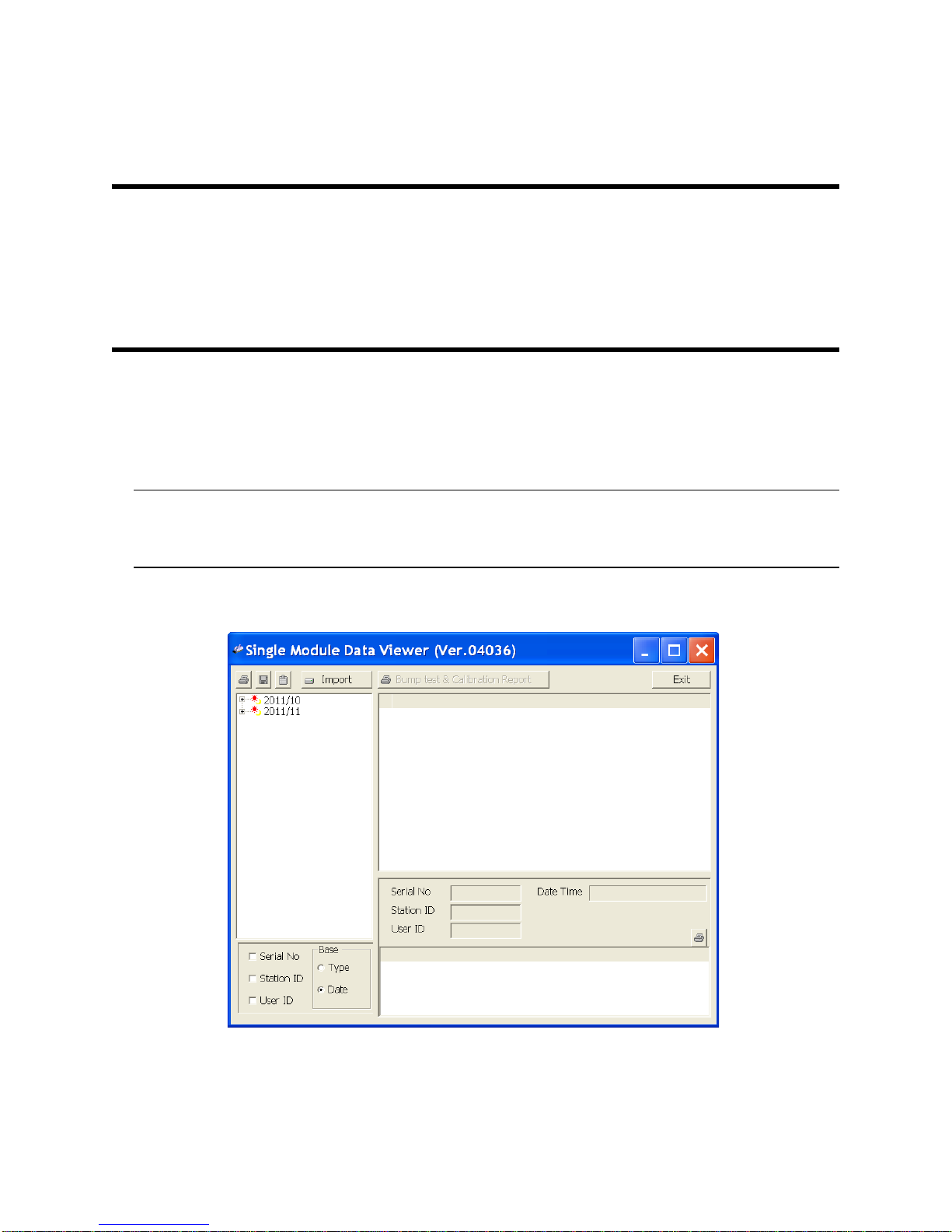
Chapter 5: Single Module Data Viewer Program
Figure 15: Single Module Data Viewer Window
Overview
The Single Module Data Viewer Program is used to view, organize, and print bump
test and calibration records that were created by the SDM-E2 while used in the
standalone configuration. It can also be used to export these records from its
database for use in other programs. This chapter describes how to use the Single
Module Data Viewer Program.
Launching the Single Module Data Viewer
Program
1. Click Start on the Windows® Icon Tray, then select Programs/Single Module
Data Viewer.
NOTE: If you are starting the software for the first time, a message window
appears informing you that a database has been created. If this occurs,
click OK.
2. The Single Module Data Viewer program is launched and the data viewing
window appears.
Overview • 72
Page 78
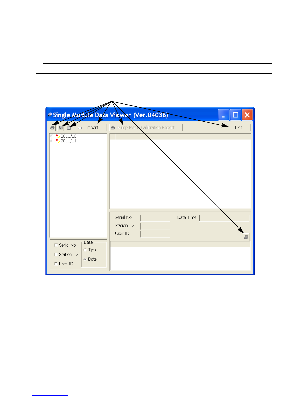
NOTE: When you start the Single Module Data Viewer Program for the first
Figure 16: Data Viewing Window
Control Buttons
Data Folders
Viewed in This
Area
Data Folders and Files
Viewed in This Area
File Content Details
Viewed in This Area
time, there will be no data in the left part of the data viewing window
since no data has been imported into the database yet.
Using the Single Module Data Viewer Program
Data Viewing Window
All of the operations that can be performed in the Single Module Data Viewer
Program can be executed from the data viewing window. There are function buttons
along the top of the window and one in the lower right that initiate the various
operations. The upper left side of the window displays the contents of the database.
The lower left corner of the window has selection boxes that allow you to organize the
data. The upper right side of the window shows the contents of the item selected in
the upper left side, and the lower right side indicates the contents of the item selected
in the area above it. In the example above, the data is organized by date.
You can do the following in the data viewing window:
• Import files into the database that were created by an SDM-E2
73 • Using the Single Module Data Viewer Program
Page 79
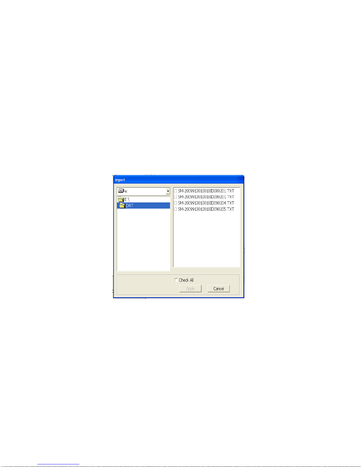
• View the bump test and calibration data saved in the database.
Figure 17: Import Window
• Delete data.
• Print bump test or calibration results (pass or fail indication only).
• Copy bump test or calibration records to the clipboard or to a particular location
on your computer or network.
• Print a bump test or calibration report that includes the results and all gas
readings.
Importing Files Into the Database
The files generated by the SDM-E2 are structured to be imported into the Single
Module Data Viewer Program database. To import data files into the database, do the
following:
1. While in the Data Viewing Window, click the Import button. The Import
Window will appear.
2. Navigate to the location of the files that you want to import into the database.
3. Select the files that you want to import or use the Check All box to select all of
the files.
4. Click the Apply button. A window will appear for a few seconds indicating that
the file or files are being imported.
5. The files are now added to the database.
Using the Single Module Data Viewer Program • 74
Page 80
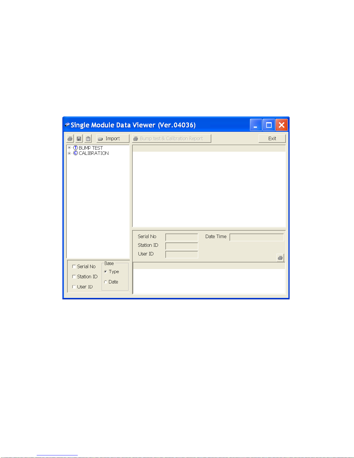
Organizing the Data
Figure 18: Data in Base Viewing Format
When viewing the data, it can be organized in two ways:
1. Base View Format
In base view format, neither of the Serial No, Station ID, or User ID selection
boxes in the lower left of the window are selected and the Base box appears
next to these selection boxes with two radio buttons. The data can be
organized by either the data Type (bump test and calibration data) or by Date
(year and month). The example below shows the data organized by Type.
75 • Using the Single Module Data Viewer Program
Page 81
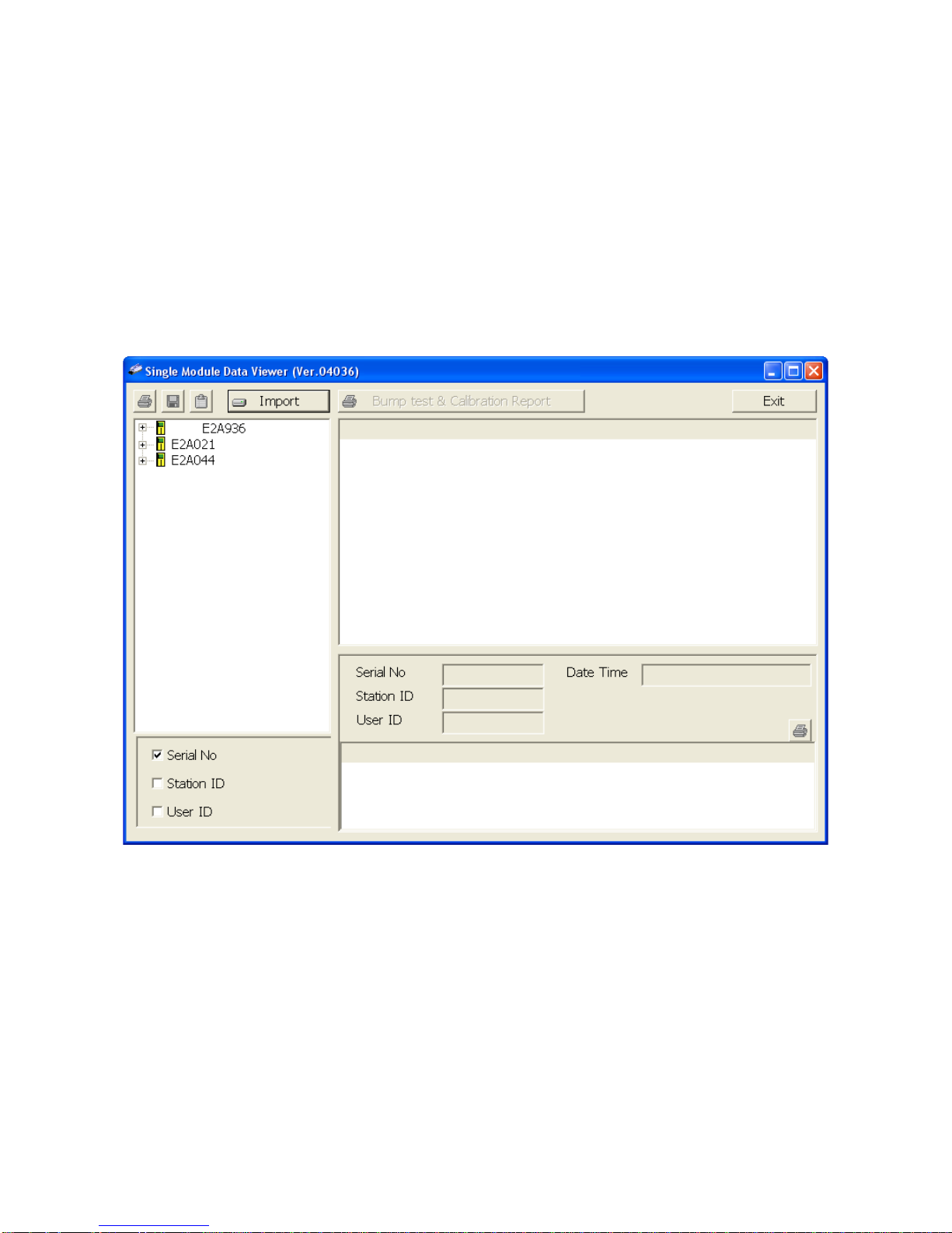
2. ID View Format
Figure 19: Data in ID Viewing Format
In ID view format, the data can be organized by one or more of the following
items depending on which selection box or boxes in the lower left corner of the
data viewing window are selected:
• Serial Number
• Station ID
• User ID
If any of these boxes is selected, the Base box disappears. The example
below shows the data organized by serial number.
Viewing the Data
Once you have selected how you want to organize the data:
1. Click the expanded view symbol (+) next to an item, folder or icon, in the left
side of the data viewing window or double click the item to view the contents
below it. Single click on an item to view the contents in the right side of the
window. If an item is expanded and you want to close it, click the (-) symbol
next to the item or double click it.
Using the Single Module Data Viewer Program • 76
Page 82
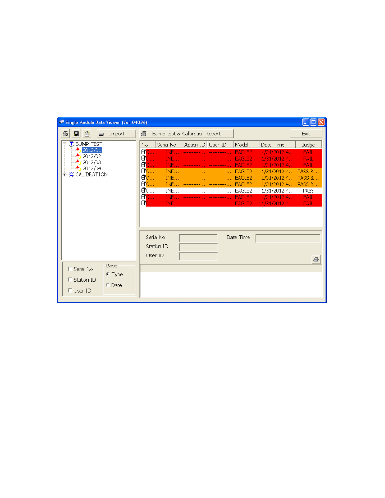
2. When an item no longer has a (+) or (-) symbol next to it, single click it and the
Figure 20: Calibration/Bump Test Files in Base View Format by Type
contents of the item will be shown on the right side of the window.
3. If you are viewing data in base view format with the data organized by type,
expand the item, bump test or calibration, you wish to view. Icons organized by
year/month will appear below the bump test or calibration icon. Click on the
item whose contents you wish to see. The bump test or calibration files will be
shown in the upper right side of the data view window.
77 • Using the Single Module Data Viewer Program
Page 83
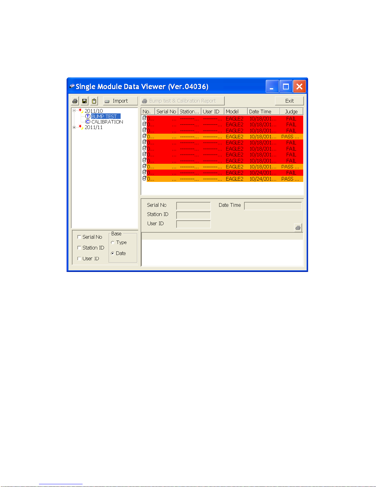
If you organize the data by date, then folders organized by year/month appear
Figure 21: Calibration/Bump Test Files in Base View Format by Date
in the left side of the window. Expand the folder you want to see and click on
the calibration or bump test folder. The calibration or bump test files will appear
in the upper right side of the window.
Using the Single Module Data Viewer Program • 78
Page 84
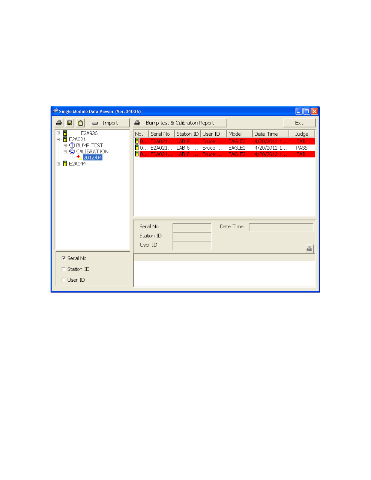
If you are viewing data in ID view format, expand the folders in the left side of
Figure 22: Calibration/Bump Test Files in ID View Format
the window until the bump test or calibration folder you wish to view is visible.
Expand the folder by clicking the (+) symbol next to it. Folders organized by
year/month will be listed below the calibration or bump test folder. Click the
folder whose contents you want to view and the calibration or bump test files in
it will be shown in the upper right side of the data view window. The example
below is organized by serial number.
4. Files that record a failed calibration or bump test on all channels are
highlighted in red. Files that record a calibration or bump test where not all
channels passed are highlighted in orange.
5. To view the file contents, click on the file in the upper right part of the data view
window that you wish to view. The contents in the file will appear in the lower
right part of the window. The contents include the instrument’s serial number,
station ID, user ID, bump test or calibration time, test gas, and gas readings
during the operation.
6. To print the files as they appear in the upper right part of the data view window,
click the print button in the upper left corner of the window. A dialog box will
appear confirming if you want to print. Click OK.
7. To print only the pass or fail result of all files in the upper right window, click the
Bump test & Calibration Report button above the files. A dialog box will
79 • Using the Single Module Data Viewer Program
Page 85

appear showing the selected printer and confirming if you want to print. Verify
that the selected printer is correct and click OK.
8. To print the complete results, pass/fail and gas readings, of one of the files in
the upper right part of the data view window, click on one of the files to select it
and then click the print button that appears above the file details in the lower
right. A dialog box will appear showing the selected printer and confirming if
you want to print. Verify that the selected printer is correct and click OK.
9. To save files as they appear in the upper right part of the data view window,
click the Save To File button to the right of the print button in the upper left
corner of the window. The Save To File button has a floppy disk icon in it. A
“Save As” dialog box will appear for you to specify the filename, file location,
and file type. Select the Text files (*.csv) choice to save the information as a
comma separated value file that may be opened with a spreadsheet program
such as Microsoft Excel.
10. To save files to the clipboard as they appear in the upper right part of the data
view window, click the Copy To Clipboard button. The Copy To Clipboard
button has a clipboard icon in it. The file will be saved to the clipboard. It can
then be pasted into a document by using the Paste command in an
application.
Deleting Data
You can delete an instrument, bump test data, or calibration data in the data view
window. The delete function is password protected to avoid accidental deletion of
instruments or data. To delete an instrument or data, perform the following:
1. Find the item you wish to delete and right click it. A window will appear that
says “Delete(D) Change Password(C)”.
2. Click on “Delete(D)”. A password entry window will appear.
3. Enter the password and click OK. The factory set password is “ABCDE” and is
case sensitive. A confirmation window will appear.
4. Click OK to complete the deletion of the selected item.
Changing the Password
The factory password is “ABCDE” and is case sensitive. You can change the
password in the data view window. To change the password perform the following:
1. Right click in the upper right or upper left part of the data view window. A
window will appear that says “Delete(D) Change Password(C)”.
2. Click on “Change Password(C)”. A window will appear prompting you for the
current password.
3. Enter the current password and click the Current Password button. A window
will appear prompting you for the new password.
4. Enter the new password and click the New Password button. A confirmation
Using the Single Module Data Viewer Program • 80
Page 86

window will appear prompting you for the new password again.
5. Enter the new password again and click the Confirm New Password button.
A window will appear indicating that the password has been changed.
6. Click OK to complete the password update.
Exiting the Program
To exit the Single Module Data Viewer Program, do the following:
1. Click the Exit button in the upper right corner of the data view window. A
confirmation window will appear.
2. Click the OK button to exit the program or the Cancel button to return to the
program.
Spare Parts List
Table 8: Spare Parts List
Part Number Description
06-1248RK Polyurethane tubing, 5/16-inch OD x 3/16-inch ID, for connecting
to inlet fittings and the exhaust fitting
06-1248RK-03 3 foot length of 5/16-inch OD x 3/16-inch ID, for connecting
calibration cylinder to inlet fittings
33-0167RK Particle air filter replacement, CF-8369
33-6010RK-04 CO
scrubber
2
49-0115RK Single-port AC adapter
49-2058RK-03 3-port AC adapter
71-0224RK Operator’s Manual, SDM-E2 Docking Station Standalone
Configuration (this document)
71-0251RK Operator’s Manual, SDM-E2 Docking Station PC Controller
Configuration
71-8006RK Product CD, SDM-E2, includes Single Module Data Viewer and
PC Controller Programs
81-0012RK-01 Calibration cylinder, 50 %LEL CH
81-0012RK-03 Calibration cylinder, 50 %LEL CH4 in air, 103 liter steel
81-0013RK-01 Calibration cylinder, 50% vol CH
81-0013RK-05 Calibration cylinder, 50% vol CH4 in N2, 58 liter steel
81 • Spare Parts List
in air, 34 liter steel
4
in N2, 34 liter steel
4
Page 87

Table 8: Spare Parts List
Part Number Description
81-0018RK-01 Calibration cylinder, 50 %LEL isobutane in air, 34 liter steel
81-0018RK-03 Calibration cylinder, 50 %LEL isobutane in air, 103 liter steel
81-0023RK-01 Calibration cylinder, H2, 8% volume in nitrogen, 34 liter steel
81-0024RK-01 Calibration cylinder, H2, 100% volume, 34 liter steel
81-0025RK-01 Calibration cylinder, 35% CO2/50% CH4, balance N2, 34 liter
steel, intended for landfill applications
81-0071RK-01 Calibration cylinder, 5000 ppm CO
81-0071RK-03 Calibration cylinder, 5000 ppm CO
in nitrogen, 34 liter
2
in nitrogen, 103 liter
2
81-0072RK-01 Calibration cylinder, 2.5 %vol CO2 in nitrogen, 34 liter
81-0072RK-03 Calibration cylinder, 2.5 %vol CO2 in nitrogen, 103 liter
81-0073RK-01 Calibration cylinder, 15 %vol CO2 in nitrogen, 34 liter
81-0073RK-03 Calibration cylinder, 15 %vol CO2 in nitrogen, 103 liter
81-0076RK Zero air cylinder,17 liter steel
81-0076RK-01 Zero air cylinder, 34 liter steel
81-0076RK-03 Zero air cylinder,103 liter steel
81-0090RK-01 Three-gas calibration cylinder, 50% LEL CH4/12% O2/50 ppm
CO, 34 liter steel
81-0090RK-03 Three-gas calibration cylinder, 50% LEL CH
/12% O2/50 ppm
4
CO, 103 liter steel
81-0103RK-01 Calibration cylinder, isobutylene, 100 ppm in air, 34 liter steel
81-0103RK-03 Calibration cylinder, isobutylene, 100 ppm in air, 103 liter steel
81-0103RK-04 Calibration cylinder, isobutylene, 100 ppm in air, 34 liter alumi-
num
81-0104RK-01 Calibration cylinder, isobutylene, 10 ppm in air, 34 liter steel
81-0104RK-03 Calibration cylinder, isobutylene, 10 ppm in air, 103 liter steel
81-0104RK-04 Calibration cylinder, isobutylene, 10 ppm in air, 34 liter aluminum
81-0142RK-02 5-gas calibration cylinder, CH4/O2/H2S/CO/SO2, 58 liter
aluminum
Spare Parts List • 82
Page 88

Table 8: Spare Parts List
Part Number Description
81-0142RK-04 5-gas calibration cylinder, CH
4/O2/H2
S/CO/SO2, 34 liter
aluminum
81-0143RK-02 Five-gas calibration cylinder, CH4/O2/H2S/CO/IBL, 58 liter
aluminum
81-0143RK-04 Five-gas calibration cylinder, CH
4/O2/H2
S/CO/IBL, 34 liter
aluminum
81-0154RK-02 Four-gas calibration cylinder, 50% LEL CH
25 ppm H
S, 58 liter aluminum
2
81-0154RK-04 Four-gas calibration cylinder, 50% LEL CH
/12% O2/50 ppm CO/
4
/12% O2/50 ppm CO/
4
25 ppm H2S, 34 liter aluminum
81-0158RK-02 Four-gas calibration cylinder, 50% LEL Isobutane/12% O2/50
ppm CO/25 ppm H2S, 58 liter aluminum
81-0158RK-04 Four-gas calibration cylinder, 50% LEL Isobutane/12% O2/50
ppm CO/25 ppm H2S, 34 liter aluminum
81-0170RK-02 Calibration cylinder, 5 ppm SO2 in nitrogen, 58 liter
81-0170RK-04 Calibration cylinder, 5 ppm SO2 in nitrogen, 34 liter
81-0175RK-02 Calibration cylinder, 10 ppm NH3 in nitrogen, 58 liter
81-0175RK-04 Calibration cylinder, 10 ppm NH3 in nitrogen, 34 liter
81-0185RK-02 Calibration cylinder, 0.5 ppm PH3 in nitrogen, 58 liter
81-0192RK-02 Calibration cylinder, 2 ppm Cl2 in nitrogen, 58 liter
81-0192RK-04 Calibration cylinder, 2 ppm Cl
in nitrogen, 34 liter
2
81-0196RK-02 Calibration cylinder, 10 ppm HCN in nitrogen, 58 liter
81-0196RK-04 Calibration cylinder, 10 ppm HCN in nitrogen, 34 liter
81-1054RK Demand flow regulator, 58/103 liter cylinders
81-1055RK Demand flow regulator, for 17/34 liter steel cylinders
81-SDME2 Docking Station for EAGLE 2
814-101-P25 Calibration kit, 5-gas with IBL, 58 liter aluminum cylinder
814-101-P25-DLV Calibration kit, 5-gas with IBL, 34 liter aluminum cylinder
83 • Spare Parts List
Page 89
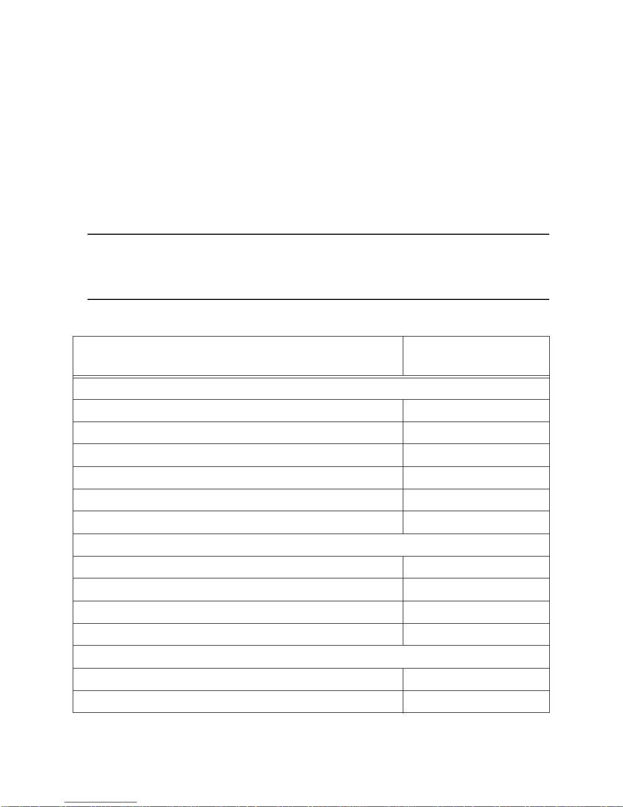
Appendix A: Bump Testing and Calibrating EAGLE 2s
with IR Sensors
The default gas port assignments for EAGLE 2s that have IR sensors installed are
different from EAGLE 2s without IR sensors and depend on the type of IR sensor.
Table 9 below outlines the default gas port assignments for various typical sensor
combinations. The gas combinations listed under the “Multiple IR Sensors” section
are listed as the channels appear on the screen. The gas port assignments can be
changed if the default assignment is not desireable. See “Setting the Gas Inlet
Parameters” on page 22 for instructions to change the gas port assignment.
NOTE: These default gas port assignments apply only to the SDM-E2 when
used in its Standalone Configuration. See the SDM-E2 PC Controlled
Configuration Operator’s Manual for a description of the PC Controller
Program’s default gas port assignments for IR sensors.
Table 9: Default Gas Port Assignments for IR Sensors
EAGLE 2 Gas Combination
Infrared Hydrocarbon Sensors
Standard 4 + IR “HC” (LEL only or autoranging) GAS 1
IR “HC” (LEL or autoranging) only GAS 1
Standard 4 + IR “IBU” (LEL only or autoranging) GAS 1
IR “IBU” (LEL or autoranging) only GAS 1
Standard 4 + IR “custom name” (LEL only or autoranging)* GAS 2
IR “custom name” (LEL or autoranging) only* GAS 1
Infrared Methane Sensors
Standard 4 + IR CH4 (LEL only or autoranging) GAS 1
IR CH4 (LEL or autoranging) only GAS 1
Standard 4 + IR CH4 (volume only) GAS 2
IR CH4 (volume only) GAS 1
IR Sensor Gas Port
Assignment
Infrared Carbon Dioxide Sensors
Standard 4 + IR CO2 (any range) GAS 2
IR CO2 (any range) only GAS 1
Spare Parts List • 84
Page 90
Table 9: Default Gas Port Assignments for IR Sensors
EAGLE 2 Gas Combination
IR Sensor Gas Port
Assignment
Multiple IR Sensors
IR CO2 (any range) + IR “HC” (LEL only or autoranging) IR CO2: GAS 2
IR “HC”: GAS 1
IR CH4 (volume only) + IR “HC” (LEL only or autoranging) IR CH4: GAS 2
IR “HC”: GAS 1
IR CH4 (volume only) + IR “IBU” (LEL only or autoranging) IR CH4 vol only: GAS 2
IR “IBU”: GAS 1
IR CH4 (volume only) + IR “custom name” (LEL only or
autoranging)*
IR CH4 vol only: GAS 1
IR “custom”: GAS 2
IR CH4 (volume only) + IR CH4 (LEL only or autoranging) IR CH4 vol only: GAS 2
IR CH4 LEL/auto: GAS 1
IR CH4 (volume only) + IR CO2 (any range) IR CH4: GAS 1
IR CO2: GAS 2
* Depending on special requirements, your infrared hydrocarbon channel’s gas name may be
something other than “HC” or “IBU”.
An IR sensor that can be bump tested or calibrated with one or more of the standard
4 sensors (catalytic LEL, oxygen, H
S, or CO) using a 3-gas or a 4-gas cylinder will
2
be assigned to GAS 1, except for an IR HC sensor that has been given a custom
name. If only an IR sensor is installed in an instrument, it will be assigned to GAS 1.
Generally, if there are 2 IR sensors installed in one EAGLE 2, the first channel listed
will be assigned to the GAS 1 port and the second channel listed will be assigned to
the GAS 2 port. If an LEL only or autoranging range of an IR CH4 or an IR HC sensor
(without a custom name) is installed, that sensor will always be assigned to GAS 1
regardless of its place in the channel order.
85 • Spare Parts List
 Loading...