

Page 1

65-2643RK-05-04
M2A Transmitter
Operator’s Manual
Part Number: 71-0387
Revision: 0
Released: 11/28/17
RKI Instruments, Inc.
www.rkiinstruments.com
Page 2

WARNING
Read and understand this instruction manual before
operating instrument. Improper use of the gas monitor
could result in bodily harm or death.
Periodic calibration and maintenance of the gas
monitor is essential for proper operation and correct
readings. Please calibrate and maintain this instrument
regularly! Frequency of calibration depends upon the
type of use you have and the sensor types. Typical
calibration frequencies for most applications are
between 3 and 6 months, but can be required more
often or less often based on your usage.
65-2643RK-05-04 M2A Transmitter Operator’s Manual
Page 3

Product Warranty
RKI Instruments, Inc. warrants gas alarm equipment sold by us to be free from defects in
materials, workmanship, and performance for a period of one year from date of shipment
from RKI Instruments, Inc. Any parts found defective within that period will be repaired
or replaced, at our option, free of charge. This warranty does not apply to those items
which by their nature are subject to deterioration or consumption in normal service, and
which must be cleaned, repaired, or replaced on a routine basis. Examples of such items
are:
Warranty is voided by abuse including mechanical damage, alteration, rough handling, or
repair procedures not in accordance with the operator’s manual. This warranty indicates
the full extent of our liability, and we are not responsible for removal or replacement costs,
local repair costs, transportation costs, or contingent expenses incurred witho u t our prior
approval.
a) Absorbent cartridges d) Batteries
b) Pump diaphragms and valves e) Filter elements
c) Fuses
THIS WARRANTY IS EXPRESSLY IN LIEU OF ANY AND ALL OTHER
WARRANTIES AND REPRESENTATIONS, EXPRESSED OR IMPLIED,
AND ALL OTHER OBLIGATIONS OR LIABILITIES ON THE PART OF
RKI INSTRUMENTS, INC. INCLUDING BUT NOT LIMITED TO, THE
WARRANTY OF MERCHANTABILITY OR FITNESS FOR A
PARTICULAR PURPOSE. IN NO EVENT SHALL RKI INSTRUMENTS,
INC. BE LIABLE FOR INDIRECT, INCIDENTAL, OR CONSEQUENTIAL
LOSS OR DAMAGE OF ANY KIND CONNECTED WITH THE USE OF
ITS PRODUCTS OR FAILURE OF ITS PRODUCTS TO FUNCTION OR
OPERATE PROPERLY.
This warranty covers instruments and parts sold to users by authorized d istributors,
dealers, and representatives as appointed by RKI Instruments, Inc.
We do not assume indemnification for any a ccident or damage caused by the opera tion of
this gas monitor, and our warranty is limited to the replacement of parts or our complete
goods.
65-2643RK-05-04 M2A Transmitter Operator’s Manual
Page 4

Table of Contents
Chapter 1: Introduction . . . . . . . . . . . . . . . . . . . . . . . . . . . . . . . . . . . . . . . . . . . . . . . . . . . . . . . 1
Overview . . . . . . . . . . . . . . . . . . . . . . . . . . . . . . . . . . . . . . . . . . . . . . . . . . . . . . . . . . . . . 1
About the M2A Transmitter . . . . . . . . . . . . . . . . . . . . . . . . . . . . . . . . . . . . . . . . . . . . . 1
About this Manual. . . . . . . . . . . . . . . . . . . . . . . . . . . . . . . . . . . . . . . . . . . . . . . . . . . . . . 1
Specifications . . . . . . . . . . . . . . . . . . . . . . . . . . . . . . . . . . . . . . . . . . . . . . . . . . . . . . . . . . 2
Chapter 2: Description . . . . . . . . . . . . . . . . . . . . . . . . . . . . . . . . . . . . . . . . . . . . . . . . . . . . . . . 3
Overview . . . . . . . . . . . . . . . . . . . . . . . . . . . . . . . . . . . . . . . . . . . . . . . . . . . . . . . . . . . . . 3
External Description . . . . . . . . . . . . . . . . . . . . . . . . . . . . . . . . . . . . . . . . . . . . . . . . . . . . 3
Internal Description . . . . . . . . . . . . . . . . . . . . . . . . . . . . . . . . . . . . . . . . . . . . . . . . . . . . 6
Chapter 3: Installation & Startup . . . . . . . . . . . . . . . . . . . . . . . . . . . . . . . . . . . . . . . . . . . . . 10
Overview . . . . . . . . . . . . . . . . . . . . . . . . . . . . . . . . . . . . . . . . . . . . . . . . . . . . . . . . . . . . 10
Mounting the M2A Transmitter . . . . . . . . . . . . . . . . . . . . . . . . . . . . . . . . . . . . . . . . . 10
Wiring the M2A Transmitter . . . . . . . . . . . . . . . . . . . . . . . . . . . . . . . . . . . . . . . . . . . . 12
Start Up . . . . . . . . . . . . . . . . . . . . . . . . . . . . . . . . . . . . . . . . . . . . . . . . . . . . . . . . . . . . . . 15
Chapter 4: Operation . . . . . . . . . . . . . . . . . . . . . . . . . . . . . . . . . . . . . . . . . . . . . . . . . . . . . . . . 18
Overview . . . . . . . . . . . . . . . . . . . . . . . . . . . . . . . . . . . . . . . . . . . . . . . . . . . . . . . . . . . . 18
Normal Operation . . . . . . . . . . . . . . . . . . . . . . . . . . . . . . . . . . . . . . . . . . . . . . . . . . . . . 18
Information Screen. . . . . . . . . . . . . . . . . . . . . . . . . . . . . . . . . . . . . . . . . . . . . . . . . . . . . 18
4 - 20 mA Signal Output Operation . . . . . . . . . . . . . . . . . . . . . . . . . . . . . . . . . . . . . . 19
Alarm Indications . . . . . . . . . . . . . . . . . . . . . . . . . . . . . . . . . . . . . . . . . . . . . . . . . . . . . 19
Chapter 5: Configuration Mode . . . . . . . . . . . . . . . . . . . . . . . . . . . . . . . . . . . . . . . . . . . . . . 23
Overview . . . . . . . . . . . . . . . . . . . . . . . . . . . . . . . . . . . . . . . . . . . . . . . . . . . . . . . . . . . . 23
Viewing & Changing M2A Parameters . . . . . . . . . . . . . . . . . . . . . . . . . . . . . . . . . . . 23
Chapter 6: Gas Type Mode . . . . . . . . . . . . . . . . . . . . . . . . . . . . . . . . . . . . . . . . . . . . . . . . . . . 26
Overview . . . . . . . . . . . . . . . . . . . . . . . . . . . . . . . . . . . . . . . . . . . . . . . . . . . . . . . . . . . . 26
Selecting the Gas Type . . . . . . . . . . . . . . . . . . . . . . . . . . . . . . . . . . . . . . . . . . . . . . . . . 26
65-2643RK-05-04 M2A Transmitter Operator’s Manual
Page 5

Chapter 7: Maintenance . . . . . . . . . . . . . . . . . . . . . . . . . . . . . . . . . . . . . . . . . . . . . . . . . . . . . 29
Overview. . . . . . . . . . . . . . . . . . . . . . . . . . . . . . . . . . . . . . . . . . . . . . . . . . . . . . . . . . . . . 29
Preventive Maintenance . . . . . . . . . . . . . . . . . . . . . . . . . . . . . . . . . . . . . . . . . . . . . . . . 29
Troubleshooting. . . . . . . . . . . . . . . . . . . . . . . . . . . . . . . . . . . . . . . . . . . . . . . . . . . . . . . 30
Calibration Frequency. . . . . . . . . . . . . . . . . . . . . . . . . . . . . . . . . . . . . . . . . . . . . . . . . . 32
Calibration . . . . . . . . . . . . . . . . . . . . . . . . . . . . . . . . . . . . . . . . . . . . . . . . . . . . . . . . . . . 33
Replacing Components of the Oxygen Detector . . . . . . . . . . . . . . . . . . . . . . . . . . . 35
Chapter 8: RS-485 Modbus Output . . . . . . . . . . . . . . . . . . . . . . . . . . . . . . . . . . . . . . . . . . . . 37
Overview. . . . . . . . . . . . . . . . . . . . . . . . . . . . . . . . . . . . . . . . . . . . . . . . . . . . . . . . . . . . . 37
Wiring the M2A in a Modbus System. . . . . . . . . . . . . . . . . . . . . . . . . . . . . . . . . . . . . 37
Using the M2A in a 4-wire Modbus System . . . . . . . . . . . . . . . . . . . . . . . . . . . . . . . 41
Modbus Mode . . . . . . . . . . . . . . . . . . . . . . . . . . . . . . . . . . . . . . . . . . . . . . . . . . . . . . . . 41
Supported Modbus Functions . . . . . . . . . . . . . . . . . . . . . . . . . . . . . . . . . . . . . . . . . . . 43
Parts List . . . . . . . . . . . . . . . . . . . . . . . . . . . . . . . . . . . . . . . . . . . . . . . . . . . . . . . . . . . . . . . . . . 48
Appendix A: Control Button Quick Reference Guide. . . . . . . . . . . . . . . . . . . . . . . . . . . . 49
Appendix B: PLC and DCS Device Wiring . . . . . . . . . . . . . . . . . . . . . . . . . . . . . . . . . . . . . 50
Appendix C: Function Code 16 Registers. . . . . . . . . . . . . . . . . . . . . . . . . . . . . . . . . . . . . . . 52
(Appendix C available from RKI Instruments, Inc. Not included in manual as normally
provided with M2A detector head.)
65-2643RK-05-04 M2A Transmitter Operator’s Manual
Page 6

Chapter 1: Introduction
Overview
This chapter briefly describes the 65-2643RK-05-04 M2A Transmitter. This chapter also
describes the 65-2643RK-05-04 M2A Trans mitter Operator’s Manual (this document). Table 1
at the end of this chapter lists the specifications for the M2A.
About the M2A Transmitter
The M2A transmitter is a fixed mount, continuous-monitoring detector head. All user
adjustable parameters may be accessed using push button switches. In addition,
calibratio n may be perf ormed no n-in trusi vely by use of a magnetic wand accessory which
activates magnetic switches through a window at the front face of the detector head.
The M2A displays the current gas reading on an OLED display which is visible through
the window in the cover (front face) and provides a 4 - 20 m A signal which indicates the
target gas reading for use by a gas moni toring controller, recording device, or
programmable controller. The M2A als o provides an RS-485 Mod bus output. Thr ee sets o f
relay contacts, two controlled by the gas alarms and one by the fail alarm, rated at 115
VAC 5 amps are available for controlling devices such as lights or horns or for controlling
higher rated relays.
Four operating modes allow you to display and change setup and calibration settings and
change the gas type. They are Calibration Mode, Configuration Mode, Gas Type Mode,
and Modbus Mode.
About this Manual
The M2A Transmitter Operator’s Manual uses the following conventions for notes, cautions,
and warnings.
NOTE: Describes additional or critical info rmation.
CAUTION: Describes pote ntial damage to equipment.
WARNING: Describes potential danger that can result in injury or death.
1 65-2643RK-05-04 M2A Transmitter Operator’s Manual
Page 7

Specifications
Table 1 lists specifications for the M2A.
Table 1: M2A Specifications
Target Gas/Detection Range Oxygen:
0 - 25.0% volume, 0.1% increments
Alarm Settings (Alarm 1/Alarm 2) 19.5% volume (decreasing)/23.5% volume (increasin g)*
Construction (housing) Explosion-proof junction box, N EM A 4
Area Classification Explosion-proof for Class I, Groups B, C, and D
Sampling Method Diffusion
Input Power 10 - 30 VDC
Controls • Three push button switches
• Three magnetic switches for non-intrusive calibration
Weight 5.5 lbs.
Signal Output • 4 to 20 mA with impedance maximums listed below
-12 VDC: 500 ohms impedance max
-24 VDC: 1000 ohms impedance max
• RS-485 Modbus
Operating Temperature -20°C to 45°C
Accuracy ± 0.5% O
*
These are the RKI factory settings. You can change the alarm settings in Configuration Mode. See
2
“Viewing & Changing M2A Parameters” on page 23.
WARNING: When using the M2A, you must follow the i nstructions and warnings in
this manual to assure proper and saf e operation of the M2A and to
minimize the risk of personal injury. Be sure to maintain and periodically
calibrate the M2A as described in this manual.
65-2643RK-05-04 M2A Transmitter Operator’s Manual 2
Page 8
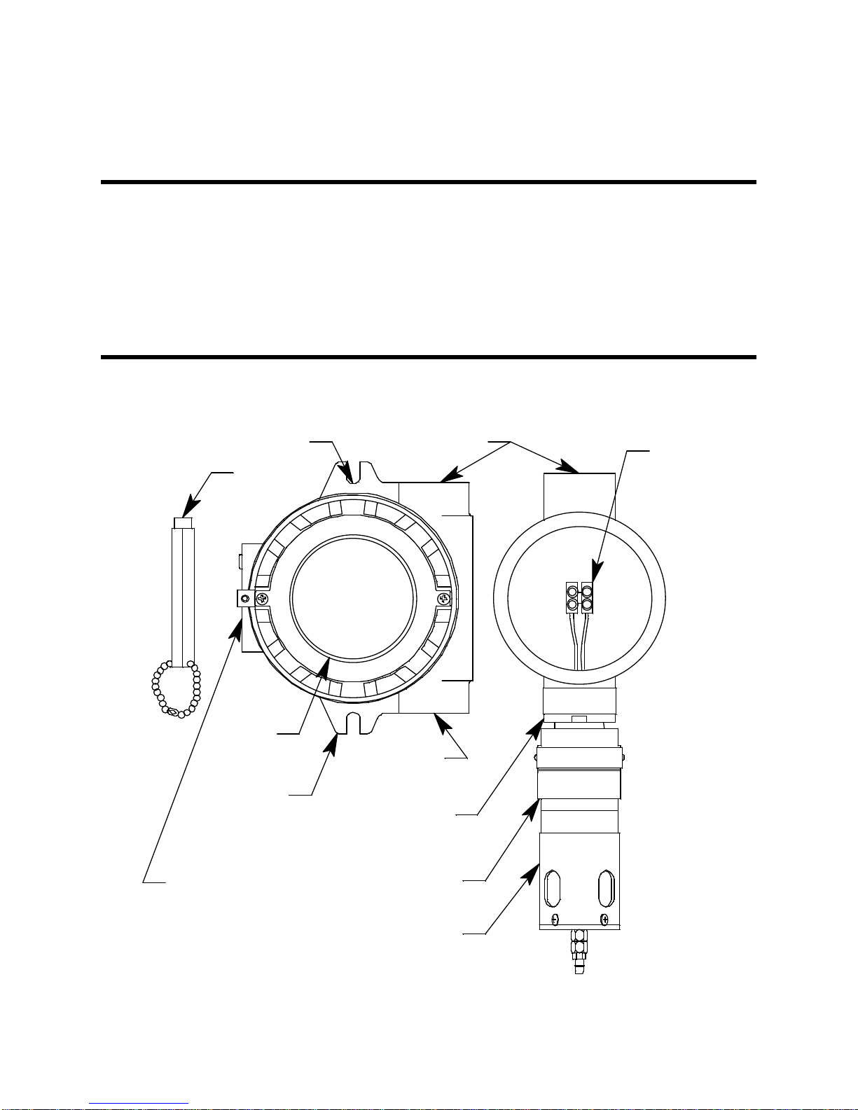
Chapter 2: Description
3/4" NPT Conduit Hub
Terminal
Strip
Magnetic
Wand
Oxygen Detector
3/4" NPT
Condui t
Hub
Detector
Junction Box
M2A
Junction
Box
Calibr ation Adapter/
Splash Gu ard
3/4" NPT
Condui t Hub
Wi ndow
M ounting Slot (2x)
Overview
This chapter describes the components of the M2A transmitter. The transmitter is a 4 - 20
mA type detector head. It consists of the oxygen detector, calibration adapter/splash
guard, terminal PCB, the M2A junction box, and the detector junction box. The twojunction-box configuration is intended for situations where the detector needs to be
installed at an inaccessible location. The detector junction box can be installed at the
inaccessible location and the M2A junction box can be installed in a more readily
accessible area.
External Description
This section describes the junction boxes and all external components of the M2A
transmitter.
3 65-2643RK-05-04 M2A Transmitter Operator’s Manual
Figure 1: M2A External Components
Page 9
M2A Junction Box
Flame Arrestor
Guard
Detector Housing Cap
Oxygen Sensor
Detector Housing Body
Cap Gasket
The M2A’s cast aluminum junction box is dust and weather resistant. The junction box
also protects the M2A and all connections made to it. Use the three 3/4 in. conduit hubs to
mount the detector to the junction box (factory installed in the bottom hub) and connect
wiring from an external device (left hub). The top hub is shipped with a factory installed
and sealed conduit plug to avoid leaks into the junction box. If necessary, the conduit plug
can be removed and the top hub can be used for wiring.
WARNING: If the top conduit hub is used for wiring, be sure to seal the threads to
ensure water does not enter the junction box. See “Wiring the M2A
Transmitter” on page 12 for complete wiring instructions.
Use the junction box’s two mounting holes to mount the M2A to a vertical surface at the
monitoring site. The window in the cover on the front of the junction box allows you to
view the OLED display and use the magnetic wand to actuate the magnetic control
switches so you can perform non-intrusive calibration. Removing the cover allows you to
access the interior of the junction box.
Detector Junction Box
The detector junction box is intended to be installed remotely from the M2A junction box.
The oxygen detector is factory installed in the bottom 3/4” NPT conduit hub. A terminal
strip is provided for wiring connections and the detector is factory wired to one side of
this terminal strip. The other side of the terminal strip is for user-supplied wiring to the
detector terminal strip located in the M2A junction box. This wiring should go through
the top 3/4” conduit hub. Three spacers installed on the back of the junction box controls
the distance of the junction box from a mounting surface.
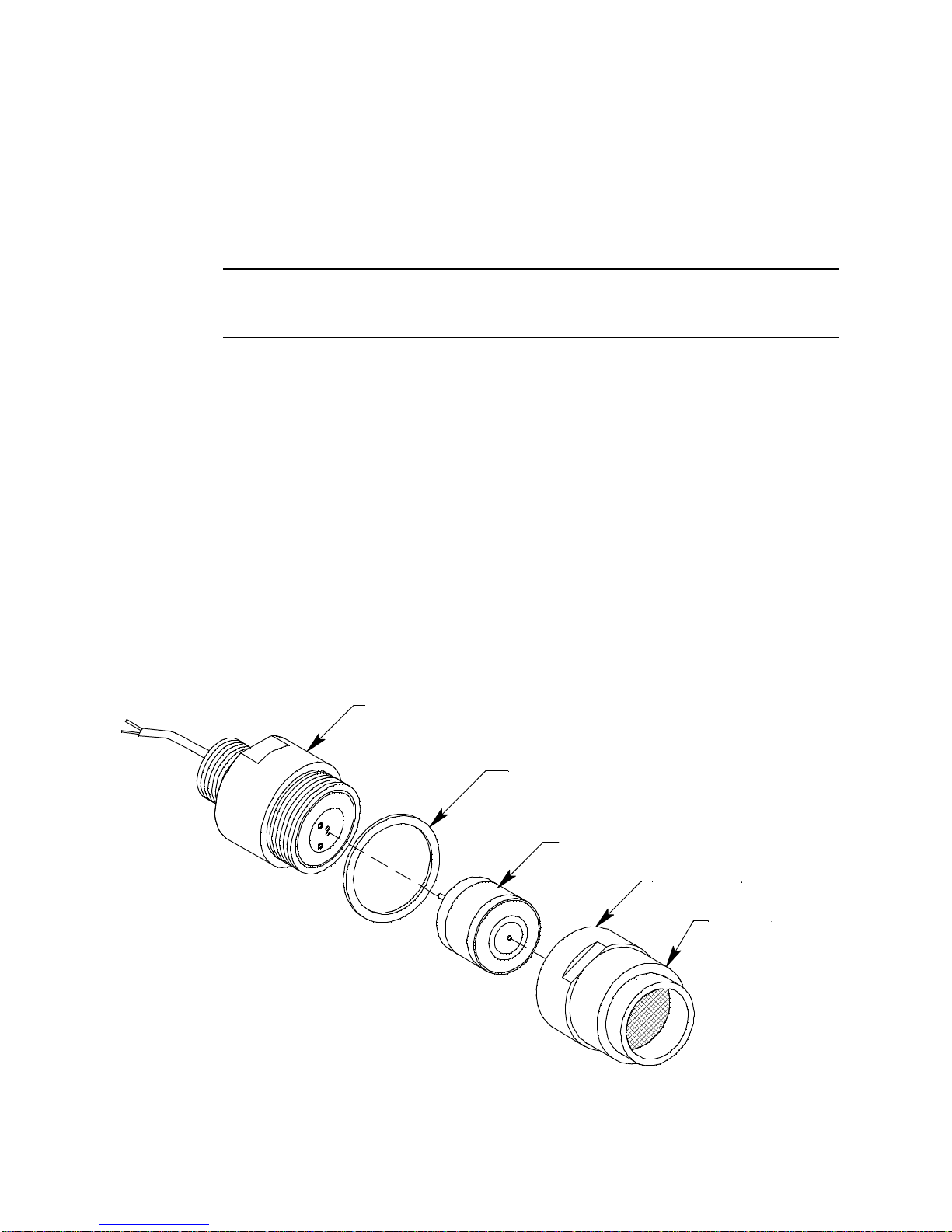
Oxygen Detector
The oxygen detector consists of the detector housing body, detector housing cap, cap
gasket, and the plug-in sensor.
Figure 2: Oxygen Detector Component Location
65-2643RK-05-04 M2A Transmitter Operator’s Manual 4
Page 10

Detector Housing Body
The detector housing body protects the electronic components within the housing. Use the
mounting threads at the top of the housing to screw the oxy gen detector into the 3/4”
NPT hub on the bottom of the detector junction box. Two wires extend from the top of the
detector housing body. Use these wires to connect the oxygen detector to the terminal
strip. One of the wires is green and one of the wires is white.
The housing includes a two-socket pattern. This socket pattern accepts the sensor’s two
pins to secure the sensor within the detector housing. A pre-amplifier, located between the
sockets and two interconnect wires, conditions the sensor’s signal be fore the signal
reaches the controller.
Housing Cap & Cap Gasket
The housing cap screws onto the detector housing. It retains th e plug-in sensor and
protects it from damage. The housing cap also includes a flame arrestor which contains
any sparks that may occur within the detector and a flame arrestor guard which protects
the flame arrestor from damage. Unscrew the detector cap to access the plug-in sensor for
maintenance or replacement. A cap gasket seals the interface between the housing and
cap. A flame arrestor guard is permanently bonded to the cap.
Plug-In Oxygen Sensor
The sensor is secured within the detector assembly by the ho using cap. Through a series
of chemical and electrical reactions, the sensor produces an electrical output that
corresponds to the detection range of the transmitter.
Calibration Adapter/Splash Guard
A calibration adapter/splash guard is installed on the oxygen detector. A fitting at the
bottom of the calibration adapter/splash guard allows a length of tubing to be connected
for calibration and routed to a more easily accessible location (near the M2A junction box
is optimal for ease of calibration). The calibration adapter/splash guard also protects th e
detector from s plashing water or direct water spray.
Magnetic Wand
The magnetic wand is a short plastic rod with a magnet in one end. It is used to actuate
the magnetic control switches on the control PCB while the junction box cover is still
installed so that non-intrusive calibration can be performed.
5 65-2643RK-05-04 M2A Transmitter Operator’s Manual
Page 11
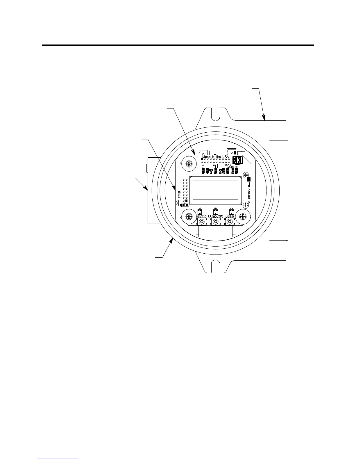
Internal Description
NO
Control PCB
M2A TRANSMITTER
RKI INSTRUMENTS
M2A JunctionBox
Terminal PC B
3/4" NPT Conduit
Opening for Wire Entry
3/4" NPT Conduit Opening, Plugged
This section describes the internal components of the M2A. The internal components of
the M2A include the terminal PCB which provides for all the wiring connect ions to the
M2A and the control PCB which displays the gas reading and has the control buttons.
65-2643RK-05-04 M2A Transmitter Operator’s Manual 6
Figure 3: M2A Internal Components
Terminal PCB
The terminal PCB is encapsulated in epoxy for protection against moisture and physical
damage. It is mounted into the rear of the junction box with three standoffs and rests on a
thin layer of foam. A banana jack is screwed into each of the standoffs and used for
mounting the control PCB. The terminal PCB converts the electrical output from the
detector to a signal which can be displayed by the OLED display, a 4 - 20 mA signal (that
is proportional to the detection range), and an RS-485 Modbus output signal. The 4 - 20
mA signal may be used by a recording device, gas monitor controller, or programmable
controller. The Modbus output may be used to connect the M2A to a Modbus network.
The terminal PCB also controls three relays, one fail and two gas alarm relays.
Two columns of plug-in style terminal strips are used to make all wiring connections to
the M2A. The column on the left consists of the power/signal, detector, and Modbus
terminal strips. The column on the right consists of the relay terminal strips. A 20 position
connector at the bottom of the terminal PCB is used to connect the terminal PCB to the
control PCB with a ribbon cable. A 5 position connector on the left side of the terminal
PCB is used by factory or field service personnel to program the M2A.
Page 12
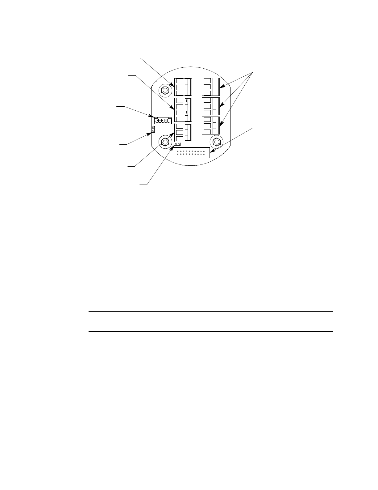
Figure 4: Terminal PCB Compon ent Location
C NC NO
ALARM 1
C NC NO
ALARM 2
C NC NO
FAIL
Modbus Terminal Strip
Ground Jumper
Programming Connector
(Factory Use)
Termination Jumper
Relay
Terminal
Strips
RS 485
A B C
- S +
PWR/SIG
+
Ribbon Cable Connector
Power/Signal Terminal Stri p
Detector Terminal Strip
TOXIC OXY
+
Power/Signal Terminal Strip
The power/signal terminal strip is a three position plug-in style terminal strip located at
the top of the left terminal column. It is used to connect 24 VDC power to the M2A and to
connect the 4 - 20 mA output signal to a device.
The signal output, the S terminal, does not have to be connected for the M2A to function.
The S terminal is used if you want to connect the 4 - 20 mA output signal to another device
such as a gas monitoring controller, chart recorder, or programmable controller (PLC).
Detector Terminal Strip
The detector terminal strip is a four position plug-in style terminal strip and is the middle
terminal strip in the left terminal column. The two terminals labeled “OXY” are used to
connect the detector to the M2A.
NOTE: The detector is factory-wired to the M2A. See “Wiring the M2A Transmitter” on
page 12 for all wiring procedures related to M2A.
Modbus Terminal Str ip
The Modbus terminal strip is a three position plug-in style termina l strip and is the
bottom terminal strip in the left terminal column. It allows connection of the M2A in to a
Modbus network.
Relay Terminal Strips
The right column of terminal strips consists of, from top to bottom, the fail, alarm 1, and
alarm 2 relay terminal strips. They are three-position plug-in style terminal strips. The
relay terminal strips are used to connect devices such as lights and horns that are
controlled by the relay contacts. The relay contacts are rated at 115 VAC, 5 am ps. The relay
contacts may also be used to control higher rated relays.
7 65-2643RK-05-04 M2A Transmitter Operator’s Manual
Page 13
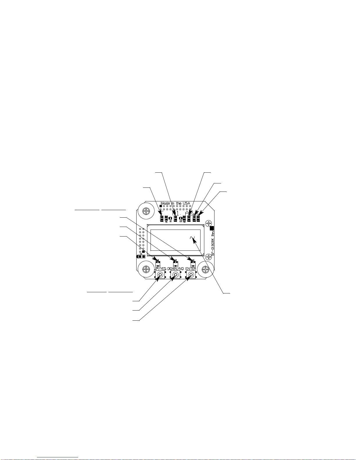
Termination Jumper
ENTER
DOWN/NO
UP/YES
Push Button
Control
Switches
Magnetic Switches
ENTER
UP/YES
DOWN/NO
Al arm 1 LED
Alar m 2 LED
Fail LED
RX LED
TX LED
M2A TRANSM ITTER
RKI INSTRUMENTS
OLED Display
A two pin header with a termination jumpe r installed is located below the Modbus
terminal strip. Leave this jumper installed un less directed to remove it for a Modbus
installation. See “Chapter 8: RS-485 Modbus Output” on page 37 for a description of using
the M2A in a Modbus system.
Ground Jumper
A two pin header with a jumper installed is located along the left side of the terminal PCB.
Leave this jumper installed unless directed to remove it for a Modbus installation. See
“Chapter 8: RS-485 Modbus Output” on page 37 for a description of using the M2A in a
Modbus system.
Control PCB
The OLED display and control switches are located on the control PCB. It is installed on
top of the terminal PCB by lining up its three spacing standoffs with the banana jacks in
the terminal PCB mounting standoffs and pushi ng it onto the banana jacks. The jacks
retain the control PCB.
65-2643RK-05-04 M2A Transmitter Operator’s Manual 8
OLED Display
The OLED display is located at the top of the control PCB. It indicates the current gas
reading and displays messages and parameters in the M2A’s programs.
Control Buttons
The M2A includes three push button switches that allow you to enter the M2A’s operating
modes, navigate through the modes, update settings, and save changes to the settings.
The push button switches are located along the bottom edge of the control PCB (see
Figure 5). The UP/YES button is on the left, the DOWN/NO button is in the middle, and
the ENTER button is on the right.
Figure 5: Control PCB Component Location
Page 14

Table 2: M2A Control Button Functions
Switch Function
UP (YES) • Saves settings
• Changes the displayed setting
• Enters the Calibration Program
• Enters Gas Type Mode (press with DOWN/NO button)
• Enters Configuration Mode (press with ENTER button)
DOWN (NO) • Cancels setting changes
• Changes the displayed setting
• Enters Gas Type Mode (press with UP/YES button)
• Enters Modbus Mode (press with ENTER button)
• Displays the Information Screen
ENTER • Initiates operations
• Enters Configuration Mode (press with UP/YES button)
• Enters Modbus Mode (press with DOWN/NO button)
• Functions as an alarm reset switch
Just above each push button switch is a magnetic switch with the same function as the
push button switch below it. The magnetic switches are for use in non-intrusive
calibration. They are actuated by bringing the magnetic wand close enough to them to
actuate them. Although the magnetic switches have the same functions as the push button
switches, it is not practical to use them for operations other than calibration because it is
not possible to actuate two magnetic switches at once with only one magnetic wand. Since
displaying the Information Screen only requires the use of one switch, the wand may be
used to show the Information Screen (see “Information Screen” on page 18).
Status LEDs
The M2A includes five status LEDs that are located above the display (see Figure 5).
• Fail LED
The fail LED turns on when the M2A is experiencing a fail condition. A fail condition
can be caused by a detector failure or low detector signal.
• Alarm 1 LED
The alarm 1 LED is on when the M2A is experiencing an alarm 1 condition.
• Alarm 2 LED
The alarm 2 LED is on when the M2A is experiencing an alarm 2 condition.
• RX & TX LED’s
These LED’s indicate data being received (RX) and transmitted (TX) when the M2A’s
Modbus output is operating.
9 65-2643RK-05-04 M2A Transmitter Operator’s Manual
Page 15
Chapter 3: Installation & Startup
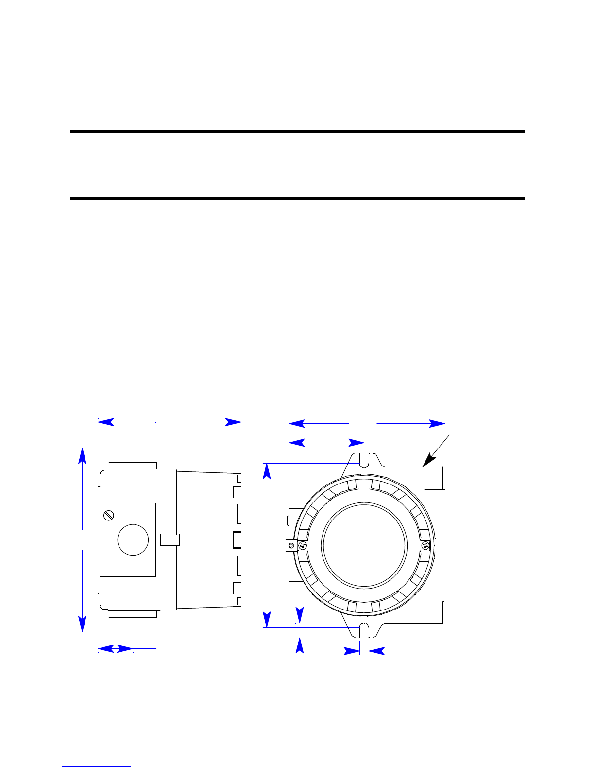
.30 (2X)
4.59
5.86
1.02
3/4 NPT
Condui t Hub,
3X
5.00
2.41
.4 7 (2 X)
5.23
Overview
This chapter describes procedures to mount the M2A Transmitter in the monitoring
environment and wire it to input power and devices.
Mounting the M2A Transmitter
1. Select a mounting site that is representative of the monitoring environment. Consider
the following when you select the mounting site.
• For the M2A junction box, select a site where the junction box is not likely to be
bumped or disturbed. Make sure there is sufficient room to perform start-up,
maintenance, and calibration proced ures. The site should be easily accessible.
• For the detector junction box, select a site where the target gas is likely to be found
first. For lighter gases, mount the detector near the ceiling; for heavier gases,
mount the detector near the floor.
• The junction boxes should be mounted no further tha n 200 feet from each other.
2. Use #10 screws through the M2A junction box’s two mounting slots to secure the
junction box to a vertical surface. Figure 6 shows the o utline and mounting
dimensions for the M2A junction box. Figure 7 shows the outline and mounting
dimensions for the detector junction box. Mount the detector junction box with the
detector facing down as shown in Figure 7.
65-2643RK-05-04 M2A Transmitter Operator’s Manual 10
Figure 6: Outline & Mounting Dimensions, M2A Junction Box
Page 16
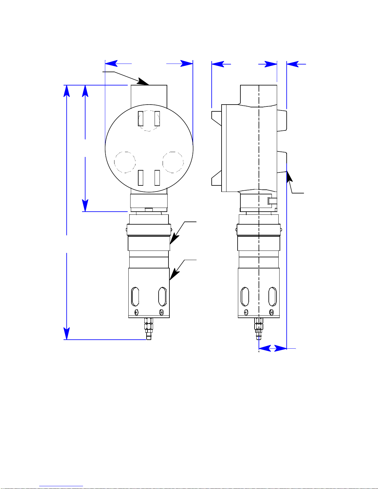
.382.70
Calibration
Adapter/
Splash
Guard
3/4 Conduit Hub
Ø3.65
Oxygen
Detector
5.25
11.40 Max
Rub ber
Space r,
3X
1.13
Figure 7: Outline & Mounting Dimensions, Detector Junction Box
3. Install 3/16 inch I.D. flexible polyurethane tubing to the fitting at the bottom of the
calibration adapter/splash guard and route it to an accessible area that is close to the
M2A junction box. See the “Parts List” on page 48 for available tubing.
11 65-2643RK-05-04 M2A Transmitter Operator’s Manual
Page 17

Wiring the M2A Transmitter
WARNING: Always verify that the power to the M2A is off before you make wiring
connections.
1. Confirm that no power is being applied to the M2A.
2. Remove the detector junction box’s cover from the junction box.
3. Remove the M2A junction box’s cover from the junction box.
4. Grasp the control PCB by its edges.
5. Gently pull until the control PCB is pulled away from the ba nana jacks. Take care not
to pull too hard and damage the cable which conn ects the control and terminal PCBs.
6. Let the control PCB hang by the cable. The terminal strips are now visible on the
terminal PCB. The control PCB may be left hanging while wiring is done. If desired,
the control PCB may be disconnected from the cable and set aside while wiring.
7. Guide a two-conductor, shielded cable or two wires in conduit through the top
conduit hub of the detector junction box. To make wiring more convenient, use wire
colors that correspond to the detector wire colors: green and white.
NOTE: Consult RKI Instruments, Inc. for cable lengths longer than 200 feet.
8. Connect the detector leads to the terminal block in the detector junction box.
9. Secure the detector junction box’s cover to the junction box.
10. Guide the other end of the two-conductor, shielded cable or two wires in conduit
through the conduit hub on the left side of the M2A junction box.
WARNING: If the top conduit hub is used for wiring, be sure to seal the threads to en sure
water does not enter the junction box. A conduit seal, which is normally
required to maintain the junction box’s hazardous location rating, will also help
to prevent water from entering through the top port.
11. To gain access to a plug-in terminal strip for wiring, pull it out of its socket by
grasping the wall between two terminal positions with needle nose pliers and pulling.
Be careful not to exert too much force on the wall to avoid damage to the terminal
strip. The detector terminal strip and the alarm 1 relay terminal strip may be removed
by grasping them with your fingers if the adjacent terminal strips have been removed.
WARNING: If the M2A is installed in a hazardous location, use appropriately rate d
conduit, conduit fittings, and appropriate construction technique that
complies with the local electrical code.
In addition, use appropriately rated conduit, conduit fittings, and
appropriate construction technique to maintain the NEMA 4
environmental rating of the junction box and avoid water entering the
junction box at the conduit hubs.
65-2643RK-05-04 M2A Transmitter Operator’s Manual 12
Page 18
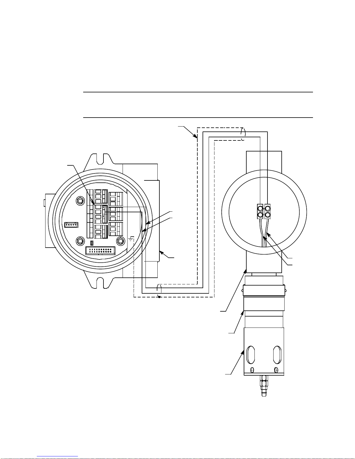
12. Pull out the detector terminal strip and connect the two wires to the terminal strip as
ALARM 2 ALARM 1
C NC NO
FAIL
C NC N O
Detector
Terminal
Strip
+ - + -
TOXIC OXY
+
+
A B C
A B C
R S 485
C NC NO
OxygenDetector
- S +
- S +
PWR/SIG
PWR/SIG
TOXIC OXY
Green
RS 485
Calibration Adapter/SplashGuard
Detector J-Box
M2A
J-Box
Green
Cable
Shield
White
White
follows (see Figure 8).
• Connect the wire corresponding to the detector’s green wire to the OXY “-”
terminal.
• Connect the wire corresponding to the detector’s white wire to the OXY “+”
terminal.
CAUTION: If shielded cable is used, leave the cable shield ’s drain wire disconnected and
insulated at the dete ctor junction bo x. You will connect the opposite e nd of the cabl e’s
drain wire to the M2A junction box’s chassis (earth) ground.
13. Reinstall the detector terminal strip into its socket.
13 65-2643RK-05-04 M2A Transmitter Operator’s Manual
Figure 8: Wiring the Detector to the M2A
Page 19

14. If shielded cable is used between the detector junction box and the M2A junction box,
connect the cable’s drain wire to an available chassis (earth) ground at the M2A
junction box. Do not connect the shield drain wire at the detector junction box.
15. Guide multi conductor shielded cable or cables or wires in conduit through the top
conduit hub of the M2A junction box. The number of cables or wires needed will
depend on whether the M2A is wired to a gas monitoring controller or just to power,
whether any relays are used, and whether the Modbus output is used.
NOTE: If the M2A is being wired to a PLC or DCS device, see “Appendix B: PLC and
DCS Device Wiring” on page 50, then continue with step 8.
Use the following recommendations to determine how to wire the M2A:
• If Modbus connections will not be used and only the PWR/SIG connections will
be used, use a two or three conductor shielded cable or two or three wires in
conduit for connections to the power/signal terminal strip depending on whether
or not the signal (S) terminal is used. The S terminal has a 4 - 20 mA output, but if
you do not need to monitor this signal and do not connect to th e S termi na l to
access this signal, the M2A will still function completely.
Table 3: Wire Size for PWR/SIG Connections
Max Distance to Controller
w/18 Gauge Wire
Max Distance to Controller
w/16 Gauge Wire
Max Distance to Controller
w/14 Gauge Wire
2,500 ft. 5,000 ft. 8,000 ft.
• If the PWR/SIG connections and one or more relays are used, route the
connections to the M2A in conduit. Use shielded cable in the conduit for the
PWR/SIG connections and unshielded cable or individual wires for the relay
connections. Make sure any wire or cable used for relay wiring is appropriately
rated for the power that it will carry.
CAUTION: If shielded cable is used for the PWR/SIG connections, leave the cable shield’s drain
wire insulated and disconnected at the M2A junction box. You will connect the
opposite end of the cable’s drain wire at the controller o r device.
• If the M2A will be wired into a Modbus network, see “Chapter 8: R S-4 85 Modbus
Output” on page 37.
65-2643RK-05-04 M2A Transmitter Operator’s Manual 14
Page 20
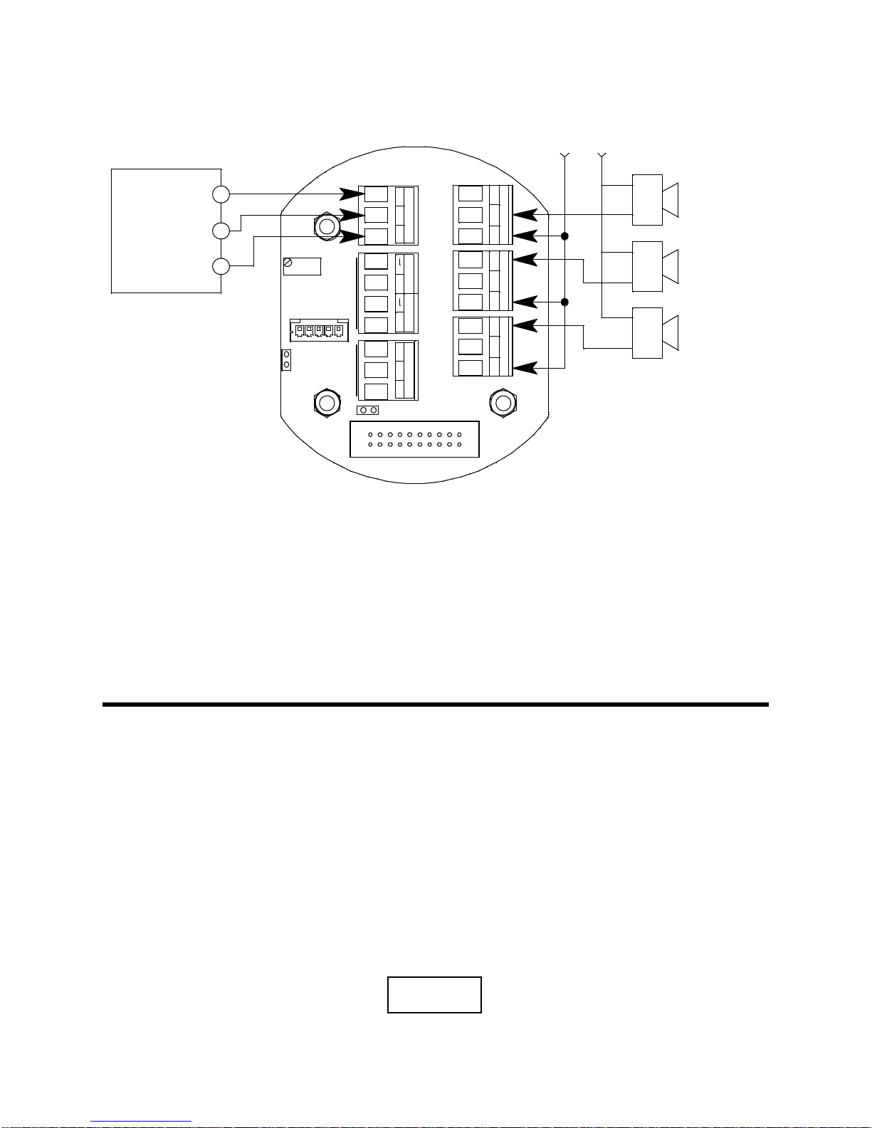
See Figure 9 below for field wiring connections to the M2A.
Alarm 1
Alarm Device
Fai l Alar m
Device
Alarm Device
Power
+
PWR/SIG
- S +
Typical Alarm
Wiring Shown
RS 485
A B C
(24 VDC) -
4 - 20 mA In (S)
(24 VDC) +
RKI Controller
Terminals
See
Detector
Wiring
TO XIC OXY
+
Alarm 2
Alarm Device
C NC NO
ALARM 1
C NC NO
ALARM 2
C NC NO
FAIL
See
Modbus
Wiring
OXYGEN
20.9 %
Start Up
Figure 9: Wiring the M2A Junction Box to a Controller and Alarm Devices
16. Re-install the control PCB (and ribbon cable if necessary). Be sure the ribbon cable is
routed down below the control PCB so it will not be damaged by the cover when it is
screwed back on.
17. Secure the M2A junction box cover to the junction box.
18. Make controller, device, and relay connecti ons as appropriate. If shielded cable is
used for t he PWR/SIG connections, connect the cable shield’s drain wire to an
available ch assis ground at th e gas monitoring controller, recor ding device, or
programmable controller.
Introducing Incoming Power
1. Complete the installation procedures described earlier in this manual.
2. Verify that all wiring connections are correct and secure.
3. Turn on the incoming power.
4. If necessary, turn on the controller or other monitoring device that is connected to the
M2A.
5. The OLED display will indicate the firmware version when the M2A is first powered
up and will then count down a one minute warm-up period before normal operation
begins. During normal operation, the display will indicate the target gas and current
gas reading. Verify that the display is indicating the target gas and current gas reading
after the warm-up period is complete and normal operation begins.
15 65-2643RK-05-04 M2A Transmitter Operator’s Manual
Page 21

NOTE: Allow the M2A’s detector to warm up for 15 minutes before you continue with
Calib?
YES/NO
the next section, “Adjusting the Fresh Air Reading.”
Adjusting the Fresh Air Reading
When the M2A is shipped from RKI Instruments, Inc., it is factory calibrated. If a full
calibration is desired at startup, see “Calibration” on page 33.
Verify that the M2A is in a fres h air environment (environm ent known to be free of
combustible or toxic gas vapors and of normal oxygen content, 20.9%).
CAUTION: If you suspect an abnormal oxygen concentration in the monitoring enviro nment,
use the calibration kit and the zero air calibration cylinder to introduce “fresh air”
to the detector and verify an accurate fresh air setting. See the “Calibration” on
page 33 for instructions on how to use a zero air cylinder when performing a fresh
air adjustment.
Non-Intrusive Fresh Air Signal Adjustment
If the M2A is installed in a classified area and non-intrusive zero adjustment is required,
follow the instructions below, but do not remove the junction box cover. Use the
magnetic wand accessory to actuate the magnetic switches instead of pushing the control
switch buttons. To actuate a magnetic switch and perform the same operation as pressing
a control switch button, touch the magnet in the end of the magnetic wand to the M2A’s
glass cover directly over the magnetic switch you wish to actuate. Touching the glass and
removing the wand is the same as pressing and releasing a button. Touching the glass and
keeping the wand in place is the same as pressing and holding a button.
WARNING: The M2A is not an active gas monitoring device during the fresh air
adjustment procedure. The 4-20 mA output signal will “freeze” at 17.4 mA
and all relays will remain in their non-alarm state while the M2A is in
Calibration Mode. The output signal will not indicate current readings
and the relays will not resume operating normally until the M2A is in
normal operation again.
NOTE: While in the calibration program, if there is no switch activity for the
calibration time-out period the unit will return to normal operation. The factory
set time-out is 15 minutes. If you want a different time-out period, see
“Viewing & Changing M2A Parameters” on page 23 for instructions to change
the calibration time-out.
1. While in normal operation, press and hold the UP/YES button for 5 seconds to enter
Calibration Mode. Release the button when the foll owing screen appears.
2. Press and release the UP/YES button to continue. The display will indicate OXYGEN CAL
Mode for a few seconds before showing FreshAir Adjust?.
3. Press and release the UP/YES button. ENTER will alternate with FreshAir on the top display
line and the current oxygen reading will be on the bottom display line.
65-2643RK-05-04 M2A Transmitter Operator’s Manual 16
Page 22

4. Press and release the ENTER button. The M2A will perform a span operation and then the
display will indicate ZERO w/Cal Gas?.
5. Press and release the DOWN/NO button. The display will indicate Leaving CAL Mode and
the M2A will return to normal operation.
17 65-2643RK-05-04 M2A Transmitter Operator’s Manual
Page 23

Chapter 4: Operation
OXYGEN
20.9 %
24.2V
v5.0L 2A
Overview
This chapter describes the M2A in normal operation. This chapter also describes the M2A
in alarm 1, alarm 2, and fail conditions and suggests responses to these conditions.
Normal Operation
Normal operation is defined as follows:
• The start-up procedure is complete.
• The M2A is not indicating an alar m 1, alarm 2, or f ail condition.
• The M2A is not in Calibration, Configuration, or Gas Type modes.
During normal operation, the M2A simultaneously displays the current gas reading, unit
of measure, and target gas.
Information Screen
The Information Screen displays the M2A’s operating voltage and firmware and hardware
information. To display the Information Screen, do the following:
1. Press and hold the DOWN/NO button for 3 seconds. The Information Screen will
appear.
2. Continue holding the DOWN/NO button to keep the Information Screen on the
display. The top line indicates the operating voltage that is connected to the M2A. The
second line indicates the firmware that is running, version 5.0 in this example, and the
M2A’s hardware version, version 2A in this example. This information may be useful
if you need to contact the factory with questions about the M2A.
3. Release the DOWN/NO button when you are done viewing the Information Screen.
The display will return to the normal operation screen within a couple of seconds.
65-2643RK-05-04 M2A Transmitter Operator’s Manual 18
Page 24

4 - 20 mA Signal Output Operation
The output at the S terminal of the power/signal terminal st rip is a 4 - 20 mA signal t hat
corresponds to the detection range of the M2A. During normal operation, this signal
tracks the gas concentration on the OLED display.
There are several circumstances where the signal output will not track the display reading
but will behave as follows:
• When the M2A is in its warm-up period, the signal output will be fixed at 17.4 mA
(20.9% oxygen).
• When the M2A’s gas type is changed, the M2A will enter Configuration Mode for you
to verify the parameter settings. When you exit Configuration Mode, the display will
indicate NEEDS CALIBRATION and will continue to indicate th is until Calibration
Mode is entered and a calibration is performed. In this situation, the signal output will
be fixed at 17.4 mA from the time Gas Type Mode is entered until the M2A is
calibrated and returns to normal operation.
• If you enter Calibration Mode, Configuration Mode, Gas Type Mode, or Modbus
Mode, the signal output will be fixed at 17.4 mA until the M2A returns to normal
operation.
• If the M2A’s input power decreases below 9.5 volts so that the M2A is in a low power
alarm, the signal output is fixed below 2.4 mA until the low power alarm is cleared.
• If the M2A goes into a fail condition, after a 30 second delay, the signal output is fixed
below 2.4 mA until the fail alarm is cleared. During the 30 second d e lay, the signal
output follows the detector output. In the case of a downscale reading, the display
and the signal output continue to track the reading down to -99% of full scale (1.15
mA).
Alarm Indications
NOTE: The M2A includes alarm on and alarm off delay settings for alarm 1 and alarm
Condition Cause Visual Indication(s)
Alarm 1
Alarm 2
1
1
2. The alarm indications described in this section operate according to the
factory set alarm settings. See Table 5 on page 24 for all the factory settings.
Table 4: Visual and Audible Alarm Indications
Decreasing gas reading at or below
the alarm 1 setpoint
Increasing gas reading at or above the
alarm 2 setpoint
• A1 LED is on
• Gas reading alternates
with ALARM-1 message
• A2 LED is on
• Gas reading alternates
with ALARM-2 message
19 65-2643RK-05-04 M2A Transmitter Operator’s Manual
Page 25

Table 4: Visual and Audible Alarm Indications
Condition Cause Visual Indication(s)
Fail • Disconnected or misconnected
detector wiring
• Display reading at -10% of full
scale or lower
• Defective components
• F LED is on
• FAIL message replaces
gas reading
NOTE: There is a 30 second
delay on the fail condition.
Low Power DC power source less than 9.5 volts. • F LED is on
• LowPower message and
actual voltage of
incoming DC power
*1If the M2A is in both an alarm 1 and an alarm 2 condition, both alarm LEDs are on and
the display alternates between the gas readin g an d the ALMS 1&2 message.
NOTE: You can select normally energized (N. EN) or normally de-energized (N. DE-
EN) alarm 1 and alarm 2 relay settings in Configuration Mode. The following
sections describe the standard factory setting for these relays which is
N. DE-EN.
The fail relay is factory set as N. EN and is not user-a djustable.
Alarm 1 Condition
Alarm 1 Condition Indications
When the gas reading reaches the alarm 1 setpoint, the M2A senses an alarm 1 condition.
The M2A alerts you to an alarm 1 condition as follows:
• The A1 LED turns on.
• The gas reading alternates with the ALARM-1 message.
• The alarm 1 relay energizes.
Responding to an Alarm 1 Condition
1. Follow your established procedure for a decreasing oxygen concentration condition.
2. Af ter the gas reading increases above the alarm 1 setpoint, press the ENTER button to
reset the alarm 1 circuit. Resetting the alarm 1 circuit turns off the A1 LED, resets the
OLED display, and de-energizes the alarm 1 relay.
NOTE: If the ENTER button is pressed while the M2A is in an alarm 1 condition, the
A1 LED will flash but all other indica tions will remain unchanged.
You cannot de-energize the alarm 1 relay until the gas reading falls below the
alarm 1 setpoint.
65-2643RK-05-04 M2A Transmitter Operator’s Manual 20
Page 26

Alarm 2 Condition
Alarm 2 Condition Indications
When the gas reading reaches the alarm 2 setpoint, the M2A senses an alarm 2 condition.
The M2A alerts you to an alarm 2 condition as follows:
• The A2 LED turns on.
• The gas reading alternates with the ALARM-2 message.
• The alarm 2 relay energizes.
NOTE: If the M2A is in bo t h an alarm 1 and alarm 2 condition, both the A1 and A2
LEDs will be on, the gas reading will alternate with the ALMS 1&2 message,
and both alarm relays will energiz e .
Responding to an Alarm 2 Condition
1. Follow your established procedure for an increasing oxygen concentration condition.
2. After the gas reading falls below the alarm 2 setpoint, press the ENTER button to reset
the alarm circuit. Resetting the alarm circuit turns off the A2 light, resets the OLED
display, and de-energizes the alarm 2 relay.
NOTE: If the ENTER button is pressed while the M2A is in an alarm 2 condition, the
A2 LED will flash but all other indica tions will remain unchanged.
You cannot de-energize the alarm 2 relay until the gas reading falls below the
alarm 2 setpoint.
Fail Condition
Fail Condition Indications
The M2A indicates a fail condition f or any of the following:
• The detector wiring is disconnected or incorrectly connected.
• The display reading is -10% of full scale or lower.
When the M2A senses a fail condition, it alerts you as follows:
• The F LED turns on.
• The gas reading is replaced by the FAIL message.
• The fail relay de-energizes.
NOTE: The fail alarm has a 30 second dela y.
Responding to a Fail Condition
1. Verify that the detector wiring is correctly and securely connected.
21 65-2643RK-05-04 M2A Transmitter Operator’s Manual
Page 27

Low Power Alarm
Low Power Alarm Indications
The M2A senses a low power condition when the DC power source is 9.5 volts or less.
WARNING: While in a low power condition, the M2A is not an active gas monitor.
When the M2A senses a low power condit ion, it alerts you as follows:
• The F LED turns on.
•The message LowPower is indicated on the top line of the OLED display and the
input voltage is displayed on the bottom line of the OLED display.
• The fail relay de-energizes.
NOTE: The low power alarm cannot be cleared using the ENTER button.
When the voltage increases to 10.0 volts, the low power alarm is cleared and the M2A will
begin its warm-up sequence.
Responding to a Low Power Condition
1. Determine and correct the cause of the low power condition.
2. When the input power increases above 10.0 volts, the M2A will begin its warm-up
sequence.
3. Verify that the M2A enters normal operation after its warm-up sequence. If necessary,
perform a fresh air adjustment. See “Adjusting the Fresh Air Reading” on page 16.
65-2643RK-05-04 M2A Transmitter Operator’s Manual 22
Page 28

Chapter 5: Configuration Mode
Enter
Config?
Overview
This chapter describes how to view and change M2A parameters using Configuration
Mode. It is accessed using the program buttons.
Configuration Mode includes a 5-minute time-out feature. If you do not press a control
button for 5 minutes, the M2A automatically returns to normal operation.
NOTE: If the M2A returns to normal operation because of a time-out, it enters a warm-
up period just as it does when it is first turned on.
If you are installing a new M2A, it has been setup at the factory. Use
Configuration Mode only if you want to change the M2A’s setup. If you want
to change the detector type see “Chapter 6: Gas Type Mode” on page 26.
Viewing & Changing M2A Parameters
1. While in normal operation, simultaneously press an d hold the UP/YES and ENTER
buttons for 5 seconds to enter Configuration Mode. Release the buttons wh en the
following screen appears.
2. If you want to exit Configuration Mode, press and release the DOWN/NO button and
the M2A will return to normal operation.
If you want to continue in Configuration Mode, press and release the UP/YES button.
The target gas and the full scale will be displayed for a few seconds before the first
adjustable pa rameter, the al arm 1 setpoint, i s displayed.
3. If you want to change the currently displayed parameter, use the UP/YES and
DOWN/NO buttons to adjust it to the desired setting, then press ENTER to continue
to the next parameter.
If the currently displayed parameter is OK, press the ENTER button to proceed to the
next parameter.
Table 5 lists the M2A parameters you can set. Table 5 also lists the factory set value for
each parameter.
23 65-2643RK-05-04 M2A Transmitter Operator’s Manual
Page 29

Table 5: Configuration Parameters
Parameter
(Factory Set Value)
ALARM-1 (level)
(19.5%)
ALARM-1 (activation)
(Decrease)
ALARM-1 (relay action)
(N. DE-EN)
ALARM-1 (relay reset)
(LATCH)
A1 OnDy (alarm 1 on delay)
(1 secs)
A1 OffDy (alarm 1 off delay)
(0 sec.)
Description
The gas reading at which the M2A initiates an alarm 1 condition.
Indicates if the alarm 1 circuit is activated by gas readings increasing
(Increase) or decreasing (Decrease) to the ALARM-1 Level.
If set as N. DE-EN, the alarm 1 relay is de-energized in normal operation
and energizes when an alarm 1 condition is initiated.
If set as N. EN, the alarm 1 relay is energized in normal operation and
de-energizes when an alarm 1 condition is initiated.
If set as LATCH, you must press the ENTER button to reset the alarm 1
circuit after the alarm 1 condition passes.
If set as SELF-RST, the M2A automatically resets the alarm 1 circuit after
the alarm 1 condition passes.
The amount of time the M2A delays activation of the alarm 1 circuit once
an alarm 1 condition is initiated. It can be set in 1 second increments
from 0 - 60 seconds, in 1 minute increments from 1 - 15 minutes, and in
15 minute increments from 15 - 60 minutes.
The amount of time the M2A delays turning off the alarm 1 circuit once an
alarm 1 condition passes. This parameter appears only if the alarm 1
relay reset setting is set to SELF-RST. It can be set in 1 second
increments from 0 - 60 seconds, in 1 minute increments from 1 - 15
minutes, and in 15 minute increments from 15 - 60 minutes.
ALARM-2 (level)
(23.5%)
ALARM-2 (activation)
(Increase)
ALARM-2 (relay action)
(N. DE-EN)
ALARM-2 (relay reset)
(LATCH)
A2 OnDy (alarm 2 on delay)
(1 secs)
A2 OffDy (alarm 2 off delay)
(0 sec.)
The gas reading at which the M2A initiates an alarm 2 condition.
Indicates if the alarm 2 circuit is activated by gas readings increasing
(Increase) or decreasing (Decrease) to the ALARM-1 Level.
If set as N. DE-EN, the alarm 2 relay is de-energized in normal operation
and energizes when an alarm 2 condition is initiated.
If set as N. EN, the alarm 2 relay is energized in normal operation and
de-energizes when an alarm 2 condition is initiated.
If set as LATCH, you must press the ENTER button to reset the alarm 2
circuit after the alarm 2 condition passes.
If set as SELF-RST, the M2A automatically resets the alarm 2 circuit after
the alarm 2 condition passes.
The amount of time the M2A delays activation of the alarm 2 circuit once
an alarm 2 condition is initiated. It can be set in 1 second increments
from 0 - 60 seconds, in 1 minute increments from 1 - 15 minutes, and in
15 minute increments from 15 - 60 minutes.
The amount of time the M2A delays turning off the alarm 2 circuit once an
alarm 2 condition passes. This parameter appears only if the al
relay reset setting is set to SELF-RST. It can be set in 1 second
increments from 0 - 60 seconds, in 1 minute increments from 1 - 15
minutes, and in 15 minute increments from 15 - 60 minutes.
arm 2
65-2643RK-05-04 M2A Transmitter Operator’s Manual 24
Page 30

Table 5: Configuration Parameters (Continued)
(Factory Set Value)
ZeroSupp
(0.5% volume)
FILTER
(5 secs)
CAL Time
(15 mins)
Auto Zero
(Enabled)
Parameter
Description
The zero suppression feature helps prevent “jumpy” readings near the
fresh air reading.
For example, if the zero suppression is 0.5%, the M2A will display a
reading of 20.9% for gas readings from 20.4% to 21.4%. It is settable
from 0 to 6% volume.
The filter feature helps “smooth out” jumpy or noisy signals from the
detector. You can set the filter from 0 seconds to 60 seconds in 5
seconds increments.
The displayed gas reading is the average reading over the previous time
period defined by the filter setting. So if the filter is set to 5 seconds, the
displayed gas reading is the average over the past 5 seconds.
The calibration time-out sets the amount of time after the last button push
while in Calibration Mode that the M2A will wait before returning to
normal operation. If the calibration time-out is set to 15 mins, then M2A
will return to normal operation automatically 15 minutes after the last
button push.
If set to Enabled, the M2A’s firmware will monitor the zero (fresh air)
reading and make automatic zero adjustments under precisely specified
conditions if it determines that a reading change is due to normal sensor
drift.
If set to Disabled, the Auto Zero function is turned off.
4. When you have scrolled through all the adjustable parameters, SAVE IT? YES/NO
appears on the display.
5. If you do not wish to save the adjustments and want to exit Configuration Mode,
press and release the DOWN/NO button. The DO OVER? YE S /NO message will
display. Press and release the DOWN/NO button. The ABORT? YES/NO message
will display. Press the UP/YES button to return to normal operat ion.
If you wish to change some of the adjustments made, press and release the DOWN/
NO button. The DO OVER? YES/N O message will display. Press and release the UP/
YES button. The Re-do Config message will display an d the M2A will return to the
first adjustable parameter. Go back to step 3 and continue.
If you wish to save the adjustme nts made, press and release the UP/YES button.
Config Saved is indicated on the display for a few seconds and the M2A returns to
normal operation.
25 65-2643RK-05-04 M2A Transmitter Operator’s Manual
Page 31
Chapter 6: Gas Type Mode
Select
GasType?
Overview
This chapter describes how to use Gas Type Mode to select the M2A’s gas typ e. The gas
type determines the target gas and detection range.
CAUTION: The target gas is factory set and does not normally need to be changed. The
standard setting for the 65-2643RK-05-04 is oxygen.
Gas Type Mode includes a 5-minute time-out feature. If you do not press a button for 5
minutes, the M2A automatically returns to normal operation .
NOTE: If the M2A enters normal operation because of a program time-out, it enters a
warm-up period just as it does when it is first turned on.
Selecting the Gas Type
1. While in normal operation or during the warm-up sequence, press and hold the UP/
YES and DOWN/NO buttons for five seconds. Release them when the following
screen appears.
2. If you want to exit Gas Type Mode, press and release the DOWN/NO button. The
display will indicate NO CHANGE and the M2A will return to normal operation.
If you want to continue in Gas Type Mode, press and release the UP/YES button. The
top display line will indicate GasType? and the bottom display line will indica te the
target gas choice.
3. Use the UP/YES or DOWN/NO button to scroll through the choices of target gas.
Table 6 below lists the choices of target gas for the M2A.
H2S 0 - 100 ppm
CO 0 - 300 ppm
Table 6: Gas Types
Gas Type
Choices
Detection Range
65-2643RK-05-04 M2A Transmitter Operator’s Manual 26
CO 0 - 200 ppm
CO 0 - 100 ppm
CL2 0 - 3.00 ppm
CL2 0 - 10.0 ppm
Page 32

Table 6: Gas Types
Gas Type
Choices
NH3 0 - 75.0 ppm
SO2 0 - 6.00 ppm
ASH3 0 - 1.50 ppm
B2H6 0 - 5.00 ppm
CLO2 0 - 1.00 ppm
F2 0 - 3.00 ppm
GEH4 0 - 1.50 ppm
HCL 0 - 15.0 ppm
HCN 0 - 15.0 ppm
HF 0 - 9.00 ppm
NO 0 - 100 ppm
O3 0 - 1.00 ppm
PH3 0 - 1.00 ppm
SIH4 0 - 15.0 ppm
Detection Range
OXYGEN 0 - 25.0% volume
4. When the desired target gas is on the display, press and release the ENTER button.
The display will ask SAVE IT? YES/NO.
5. To discard the gas type change, press and release the DOWN/NO button. The display
will ask DO OVER? YES/NO. Press the DOWN/NO button. The display will ask
ABORT? YES/NO. Press the UP/YES button. The M2A will return to normal
operation without changing the gas type.
To save the gas type, press and release the UP/YES button. The displa y will indicate
Gas Type Updated, the display will indicate the target gas and the detection range for
a few seconds, and then the M2A will enter Configuration Mode automatically so that
the parameter settings in Configuration Mode can be verified or changed.
6. While in Configuration Mode press and release the ENTER butt on to accept the
displayed parameter setting and move to the next one. Use the UP/YES and DOWN/
NO buttons to adjust a s et tin g . See “ Chapter 5: Configuration Mode” o n pag e 23 for a
complete description of Configuration Mode.
7. When you have reviewed and accepted the last item in Configuration Mode by
pressing the ENTER button, displa y will ask SAVE IT? YES/NO.
8. To save the configuration settings, press and release the UP/YES button. The display
will indicate Config Saved and the M2A will begin its warm-up sequence.
To discard the settings and review them again, press the DOWN/NO button. The
display will ask DO OVER? YES/NO. Press the UP/YES button and the display will
indicate Re-do Config, then display the target gas and the detection range for a few
seconds before returning to Configuration Mode. Repeat steps 6 - 8 until the settings
27 65-2643RK-05-04 M2A Transmitter Operator’s Manual
Page 33

are as desired.
9. After the M2A completes its warm-up sequence, the display will indicate CAL
NEEDED. Since the gas type has been changed, a successful calibration must be
performed before the M2A can enter normal operation.
10. Press and release the UP/YES button to enter Calibration Mode. Normally, you must
hold the UP/YES button for 5 seconds to enter Calibration Mode, but since a
calibration is required, only a momenta r y push is needed to enter Calibration Mode
after changing the gas type.
11. See “Calibration” on page 33 for calibration instructions.
NOTE: When calibrating an M2A after changing the gas type, the M2A will not ask if
you want to calibrate, or whether you want to perform a fresh air adjustment
zero adjustme nt . Since a complet e calibration is required, the calibrati on
sequence will proceed without asking if you want to perform certain
operations.
65-2643RK-05-04 M2A Transmitter Operator’s Manual 28
Page 34

Chapter 7: Maintenance
Overview
This chapter describes procedures for performing preventive maintenance,
troubleshooting, calibrating the M2A, and replacing field replaceable parts.
Preventive Maintenance
This section describes a recommended preventive maintenance schedule to ensure the
optimum performance of the M2A. It includes daily, monthly, and quarterly procedures.
Daily
Verify a display reading of 20.9% volu me. Investigate significant changes in the reading.
Monthly
This procedure describes a test to verify that the M2A responds properly to the target gas.
NOTE: Performing a response test on the M2A may cause alarms. If you do not want
external alarms to a ctua te, di s able any external alarms during t h e res pon s e te st
to avoid unwanted external alarm indication s .
NOTE: The following procedure assumes the use of a calibration kit which includes a
calibration gas cylinder and a fixed flo w regulator with an on/off knob.
1. D isable all external alarms if external alarm indications are not desired during the
response test.
2. Screw the calibration gas cylinder into the fixed flow regulator.
3. Use the flexible tubing coming from the calibration adapter/splash guard to connect
the regulator to the calibration adapter/splash guard.
4. Turn the regulator knob counterclockwise to open the regulator.
5. Allow calibration gas to flow for the length of time determined in “Determining
Response Time” on page 32.
6. Verify that the display reading is within ± 20% of the gas concentration.
NOTE: If the reading is not within ± 20% of the gas concentration, calibrate the M2A as
described in “Calibration” on page 33.
7. Turn the regulator knob clockwise to close the regulator.
8. Unscrew the calibration gas cylinder from the fixed flow regulator.
9. Disconnect the calibration adapter/splash guard’s flexible tubing from the regulator.
NOTE: Do not disconnect the flexible tubing from the calibration adapter/splash guard.
29 65-2643RK-05-04 M2A Transmitter Operator’s Manual
Page 35

10. If external alarms have been disabled, enable them when the display returns to a
normal fresh air reading.
11. Store the components of the calibration kit in a safe place.
Quarterly
Calibrate the M2A as described in “Calibration” on page 33. See “Calibration Frequency”
on page 32 for a discussion of calibration frequency guidelines.
Troubleshooting
The troubleshooting guide describes symptoms, probable causes, and recommended
action for problems you may encounter with the M2A.
NOTE: This troubleshooting guide describes M2A problems only. If the M2A is
connected to a controller, see the controller operator’s manual for problems you
may encounter with the controller.
Table 7: Troubleshooting the Carbon Monoxide Detector
Condition Symptom(s) Probable Causes Recommended Action
No Power The display backlight
is off and the display
screen is blank.
Frequent or
Suspect
Alarms
The M2A alerts you
to frequent or suspect
alarms while th e
fresh air readings
remain on 20.9%.
• The power wiring is
disconnected or
misconnected.
• The display cable is
disconnected or
misconnected.
•The M2A is
experiencing false
readings due to RFI
or EMI.
• The detector wiring
is disconnected,
misconnected, or
intermittent.
1. Verify that the wiring to the
power source or controller is
correct and secure.
2. Verify that the ribbon cable
connecting the terminal PCB to
the control PCB is securely
installed. This ribbon cable plugs
into a connector on the top edge
of the control PCB and on the
bottom of the terminal PC B.
3. If the power difficulties continue,
contact RKI for further
instruction.
1. Verify that the M2A wiring is
properly shielded. See “Wiring
the M2A Transmitter” on page 12.
2. Verify that the detector wiring is
correct and secure.
3. Increase the alarm on delay
setting in Configuration Mode.
4. If the frequent or suspect alarm
difficulties continue, contact RKI
for further instruction.
65-2643RK-05-04 M2A Transmitter Operator’s Manual 30
Page 36

Table 7: Troubleshooting the Carbon Monoxide Detector (Continued)
Condition Symptom(s) Probable Causes Recommended Action
Flickering
Display
Fail
Condition
The display reading
flickers often.
• M2A indicates a
fail condition.
• Controller
indicates a fail
condition.
•The M2A is
experiencing false
readings due to RFI
or EMI.
•The noise filter
setting is too low.
•The zero
suppression setting
is too low.
• The display screen
is malfunctioning.
• The detector wiring
to the terminal PCB
is disconnected or
misconnected.
• The wiring from the
M2A to the
controlle r is
disconnected or
misconnected.
•The detector fresh
air signal is low
enough to cause a
fail condition.
•The detector is
malfunctioning.
•The terminal or
display PCB is
malfunctioning.
1. Verify that the M2A wiring is
properly shielded. See “Wiring
the M2A Transmitter” on page 12.
2. Verify that the detector wiring is
correct and secure.
3. Increase the filter setting in
Configuration Mode.
4. Increase the zero suppression
setting in Configuration Mode.
5. If the display diff iculties continue,
contact RKI for further
instruction.
1. Verify that the detector wiring is
correct and secure.
2. Verify that the wiring between the
M2A and the controller is correct
and secure.
3. Calibrate the M2A.
4. If the fail condition continues,
replace the detector.
5. If the fail condition continues,
contact RKI for further
instruction.
Slow or No
Response/
Difficult or
Unable to
Calibrate
•M2A responds
slowly or does not
respond to
response test.
•Unable to
successfu l ly set
the fresh air or
zero reading
during
calibration.
•M2A requires
frequent
calibration.
Note: See “Calibration
Frequency” on page 32 for
calibration frequency
guidelines.
• The calibration
cylinder is low, outdated, or defective.
• The calibration gas
flow rate is too low.
• The calibration gas
is not an
appropriate
concentration.
•The detector is
malfunctioning.
• The terminal PCB is
malfunctioning.
• The flexible tubing
to the calibration
adapter/splash
guard has become
kinked, blocked, or
disconnected.
1. Verify that the calibration cylinder
contains an adequate supply of a
fresh test sample.
2. Verify that the regulator used for
calibration is a 0.5 LPM regulator.
3. Verify that the calibration gas
concentration is appropriate for
the transmitter. The concentration
should be in the detection range,
preferably about half of the
detection range.
4. Verify that the flexible tubing to
the calibration adapter/splash
guard is clear and connected to
the calibration adapter/splash
guard.
5. If the calibration/response
difficulties continue, replace the
detector.
6. If the calibration/response
difficulties continue, contact RKI
for further instruction.
31 65-2643RK-05-04 M2A Transmitter Operator’s Manual
Page 37

Calibration Frequency
Although there is no particular calibration frequency that is correct for all applica tions, a
calibration frequency of every 3 to 6 months is adequate for most oxygen transmitter
applications. Unless experience in a particular application dictates otherwise, RKI
Instruments, Inc. recommends a calibration frequency of every 3 months.
If an application is not very demanding, for example detection in a clean, temperature
controlled environment where combustible and toxic gases are not normally present and
calibration adjustm e nts are m in i mal at cal i brat ion, then a calibration frequency of every 6
months is adequate.
If an application is very demanding, for example if combustible and toxic gases are
present often and in significant con c entrations or the environment is not well controlled,
then more frequent calibration than every 3 months may be necessary.
Determining Response Time
Since the detector junction box is installed remotely from the M2A, the response time of
the detector will depend on the length of flexible tubing th at is attached to the calibration
adapter/splash guard. To determine the response time based on the len gth of tubing
connected:
1. Place the M2A into its calibration mode or disable external alarms.
2. Note the current gas reading displayed at the M2A.
3. Screw the regulator into the 100% nitrogen calibration cylinder.
4. Use the flexible tubing coming from the calibration adapter/splash guard to connect
the regulator to the calibration adapter/splash guard.
5. Turn the regulator’s on/off knob counterclockwise to open the regulator. Gas will
begin to flow. Take note of the time or start a stopwatch.
6. When you first start to notice a decrease in the gas reading, note how much time
passed between starting the gas flow and noticing a readi ng re sponse.
7. Turn the regulator’s on/off knob clockwise to close the regulator.
8. Unscrew the regulator from the calibration cylinder.
9. Disconnect the calibration adapter/splash guard’s flexible tubing from the regulator.
NOTE: Do not disconnect the flexible tubing from the calibration adapter/splash guard.
10. Add 1 minute to the length of time determined in step 6. This is the response time for
the detector. When performing a response test, fresh air adjustment, or zero
adjustment, gas must be applied for this length of time.
65-2643RK-05-04 M2A Transmitter Operator’s Manual 32
Page 38

Calibration
This section describes how to calibrate the M2A transmitter. It includes procedur es to
prepare for calibration, enter Calibration Mode, adjust the fresh air (span) setting, adjust
the zero setting, and return to normal operation.
WARNING: The M2A is not an active gas monitoring device during the calibration
procedure. The 4-20 mA output signal will “freeze” at 17.4 mA and all
relays will remain in their non-alarm state while the M2A is in
Calibration Mode. The output signal will not indicate current readings
and the relays will not resume operating normally until the M2A is in
normal operation again.
NOTE: The following procedure assumes the use of a calibration kit which includes a zero air
(20.9% oxygen) calibration cylinder to set the fresh air reading, a 100% nitrogen (0%
oxygen) calibration gas cylinder to set the zero reading and a fixed flow regulator with
an on/off knob. A cylinder with up to an 18% oxygen concentration may be used
instead of a 100% nitrogen cylinder to set the zero reading.
NOTE: While in the calibration program, if there is no switch activity for the
calibration time-out period the unit will return to normal operation. See
“Viewing & Changing M2A Parameters” on page 23 for instructions to set the
calibration time-out.
NOTE: The following procedure assumes that the oxygen concentration in the calibration area
is not normal, 20.9%, but is oxygen deficient. If a fresh air environment can be verified,
applying zero air to the detector is not necessary when adjusting the fresh air (span)
setting.
Non-Intrusive Calibration
If the M2A is installed in a classified area and non-intrusive calibration is required, follow
the instructions below, but do not remove the junction box cover. Use the magnetic wand
accessory to actuate the magnetic switches instead of pushing the control switch buttons.
To actuate a magnetic switch and perform the same opera tion as pressing a cont rol switch
button, touch the magnet in the end of the magnetic wand to the M2A’s glass cover
directly above the magnetic switch you wish to actuate. Touching the glass and removing
the wand is the same as pressing and releasing a button. Touching the glass and keeping
the wand in place is the same as pressing and holding a button.
Calibration Gas Response Memory Feature
The M2A has the capability to “remember” the detector’s response to the calibration gas after the
gas is removed from the detector during the fresh air or zero adjustment procedure. This feature
enables one person to perform a calibration if the detector is mounted remotely from the M2A.
When zero air is applied to the M2A during a fresh air adjustment, the M2A will freeze the display
reading at the highest response and the M2A will continue to display this reading and retain it in its
memory until the fresh air adjustment procedure is completed. When calibration gas is applied to
the M2A during a zero adjustment, the M2A will freeze the display reading at the lowest response
to the calibration gas. The calibration gas can then be removed and the M2A will continue to
display this reading and retain it in its memory until the zero adjustment procedure is completed.
33 65-2643RK-05-04 M2A Transmitter Operator’s Manual
Page 39

Adjusting the Fresh Air Reading
Calib?
YES/NO
1. While in normal operation, press and hold the UP/YES button for 5 seconds to enter
Calibration Mode. Release the button when the following screen appears.
2. If you want to continue with calibration, press and release the UP/YES button to continue. The
display will indicate OXYGEN CAL Mode for a few seconds before showing FreshAir
Adjust?.
If you want to exit Calibration Mode, press and release the DOWN/NO button. The M2A will
indicate Leaving CAL Mode and the M2A will return to normal operation.
3. To continue with adjusting the fresh air (span) reading, press and release the UP/YES button.
ENTER will alternate with FreshAir on the top display line and the current oxygen reading
will be on the bottom display line.
To skip adjusting the fresh air reading, press and release the DOWN/NO button. The display
will indicate ZERO w/Cal Gas?. Skip to the next section, “Adjusting the Zero Setting”.
4. Screw the zero air cylinder into the fixed flow regulator.
5. Use the flexible tubing coming from the calibration adapter/splash guard to connect
the regulator to the calibration adapter.
6. Turn the regulator knob counterclockwise to open the regulator.
7. Allow zero air to flow for the length of time determined in “Determining Response
Time” on pag e 32.
8. Turn the regulator knob clockwise to close the regulator.
9. Unscrew the zero air cylinder from the fixed flow regulator. Leave the calibration
adapter/splash guard’s flexible tubing connected to the regulator. The M2A will
continue to display the maximum gas response on the display and retain the response
level in its memory.
10. Press and release the ENTER button. The M2A will perform a fresh air adjustment
and the display will indicate ZERO w/Cal Gas?.
NOTE: If the fresh air adjustment fails, see “Troubleshooting” on page 30 for
recommended actions.
Adjusting the Zero Setting
1. If you want to continue with adjusting the zero setting, press and release the UP/YES
button. APPLY will alternate wit h ZERO Gas on the top display line and the current
gas reading will be on the bottom displa y line.
If you want to skip adjusting the zero reading, press a nd release the DOWN/NO
button. The display will indicate Leaving Cal Mode and the M2A will return to
normal operation.
2. Screw the 100% nitrogen gas cylinder into the fixed flow regulator.
3. Turn the regulator knob counterclockwise to open the regulator.
4. Allow calibration gas to flow for the length of time determined in “Determining
Response Time” on page 32.
65-2643RK-05-04 M2A Transmitter Operator’s Manual 34
Page 40

5. Turn the regulator knob clockwise to close it.
6. Unscrew the calibration gas cylinder from the fixed flow regulator. The M2A will
continue to display the minimum gas response on the display and retain the response
level in its memory.
7. Adjust the oxygen reading up or down to match the 100% nitrogen cylinder oxygen
concentration of 0% by using the UP/YES and DOWN/NO buttons.
NOTE: If a cylinder other than a 100% nitrogen (0% oxygen) cylinder is used to set the zero
reading, such as a cylinder with 12% oxygen, set the zero reading to match the
cylinder’s oxygen concentration.
8. The M2A will perform a zero operation. The display will indicate ZERO Gas PASS
for a few seconds, then indicate ZERO Gas SAVED before indicating Leaving CAL
Mode for a few seconds.
NOTE: If the zero adjustment fails, see “Troubleshooting” on page 30 for
recommended actions.
9. The display will now alternate between the normal operation screen and the message
REMOVE CAL GAS for 1 minute. If the calibration gas has not been removed from
the detector, remove it now to avoid unwanted alarms.
During this 1 minute period, the signal output will remain fixed at 17.4 mA and the
relays will remain in their non-alarm sta te to a v oid unwanted alarms while the
calibration gas clears from the detector. At the end of the 1 minute period, the
REMOVE CAL GAS message will st op appe ar ing and th e M2A w ill ret urn t o no rmal
operation.
10. Disconnect the calibration adap ter/splash guard’s flexible tubing from the regulator.
NOTE: Do not disconnect the flexible tubing from the calibration adapter/splash guard.
11. Store the components of the calibration kit in a safe place.
Replacing Components of the Oxygen Detector
This section includes a procedure to replace the oxygen plug-in sensor and the entire
detector assembly. In most cases, it is not necessary to replace the entire detector assembly.
Replacing the Plug-In Oxygen Sensor
1. Turn off or unplug power to the M2A.
2. Unscrew t he calibration adapter/splash guard from the detector housing cap.
3. Unscrew the detector housing cap from the detector housing body. Make su re not to
lose the cap gasket.
4. Unplug and remove the oxygen sensor.
5. Carefully plug the replacement se nsor into the two-socket pattern that is located in
the detector housing.
6. Make sure the cap gasket is in place and screw the detector housing cap back onto the
detector housing body.
35 65-2643RK-05-04 M2A Transmitter Operator’s Manual
Page 41

7. Screw the calibration adapter/splash gua rd back on to the detector housing cap.
8. Turn on or plug in power to the M2A.
CAUTION: Allow the replacement sensor to warm up for 5 minutes before you continue with the
next step.
9. Calibrate the transmitter as described in the “Calibration” on page 33 .
Replacing the Oxygen Detector
NOTE: In most cases, it is only necessary to replace the plug-in oxygen sensor.
1. Turn off or unplug power to the M2A.
2. Remove the detector junction box cover.
3. Unscrew t he calibration adapter/splash guard from the detector housing cap.
4. Disconnect the detector leads from the terminal block in the d e tector junction box.
Note the position of the color-coded leads as you remove th em.
5. Unscrew the detector from the dete ctor junction box.
6. Guide the detector leads of the replacement detector through the bottom conduit hub
of the detector junction box, then screw the mounting threads of the detector int o th e
conduit hub. If necessary for environmental conditions, apply thread sealant or teflon
tape to the hub and/or detector threads to seal them.
7. Connect the detector leads to the terminal block the same way the old detector wa s
wired (see Figure 8 on page 13).
8. Screw the calibration adapter/splash gua rd onto the new detector housing cap.
9. Reinstall the detector junction box cover.
10. Turn on or plug in power to the M2A.
CAUTION: Allow the replacement detector to warm up for 5 minutes before yo u c ontinue with
the next step.
11. Calibrate the replacement detector as described in “Calibration” on page 33.
65-2643RK-05-04 M2A Transmitter Operator’s Manual 36
Page 42

Chapter 8: RS-485 Modbus Output
Overview
This chapter describes the M2A’s RS-485 Modbus output and how to con f igure the M2A
to make use of it. It also discusses how to wire the M2A into a Modbus system.
The M2A provides an RS-485 serial communications interface. It is a Modbus Slave
Device, supporting 2-wire RS-485 Modbus RTU serial communications.
Wiring the M2A in a Modbus System
The M2A is a 2-wire Modbus RTU device. When wiring the M2A into a Modbus system,
adhere to standard Modbus wiring practices per the Modbus Over Serial Line
Specifica tion an d Impl emen tati on Guide V1.0 o r later. This docum ent can b e foun d online
at www.modb u s.org/spe c s. p h p .
The Modbus protocol supports a maximum of 247 unique slave addresses (1-247). The
M2A’s line driver provides for up to 128 M2As to be connected together without the need
for a repeater. Figure 12 & Figure 13 below illustrate typical M2A wiring configurations. If
more than 128 M2As need to be connected together, RS-485 repeater(s) should be used
such that no more than 128 M2As reside on any given network segment.
CAUTION: The network segment can only support 128 units if RKI M2As are being used. The
use of any other instruments will lower the number of units that may reside on any
given network segment.
NOTE: Only M2As produced after November 2010 have the capability to support a
128-unit segment. M2As produced before November 2010 can only support a
32-unit segment.
The MODBUS terminal strip is located on the terminal PCB (see Figure 4 on page 7). The
following signals are avail able at the Modbus terminal strip:
Table 8: Modbus Terminal Strip Signals
Modbus Terminal Label (RS-485
Name)
AD0
BD1
CCommon
Modbus Signal Name
Ground Jumper
The M2A includes a 2-pin ground header (see Figure 4 on page 7) that is used when the
M2A is used in a Modbus system. Every M2A is supplied with a ground jumper (a jumper
block) installed onto this header. If the M2A isn’t wired into a Modbus system or if it is
37 65-2643RK-05-04 M2A Transmitter Operator’s Manual
Page 43
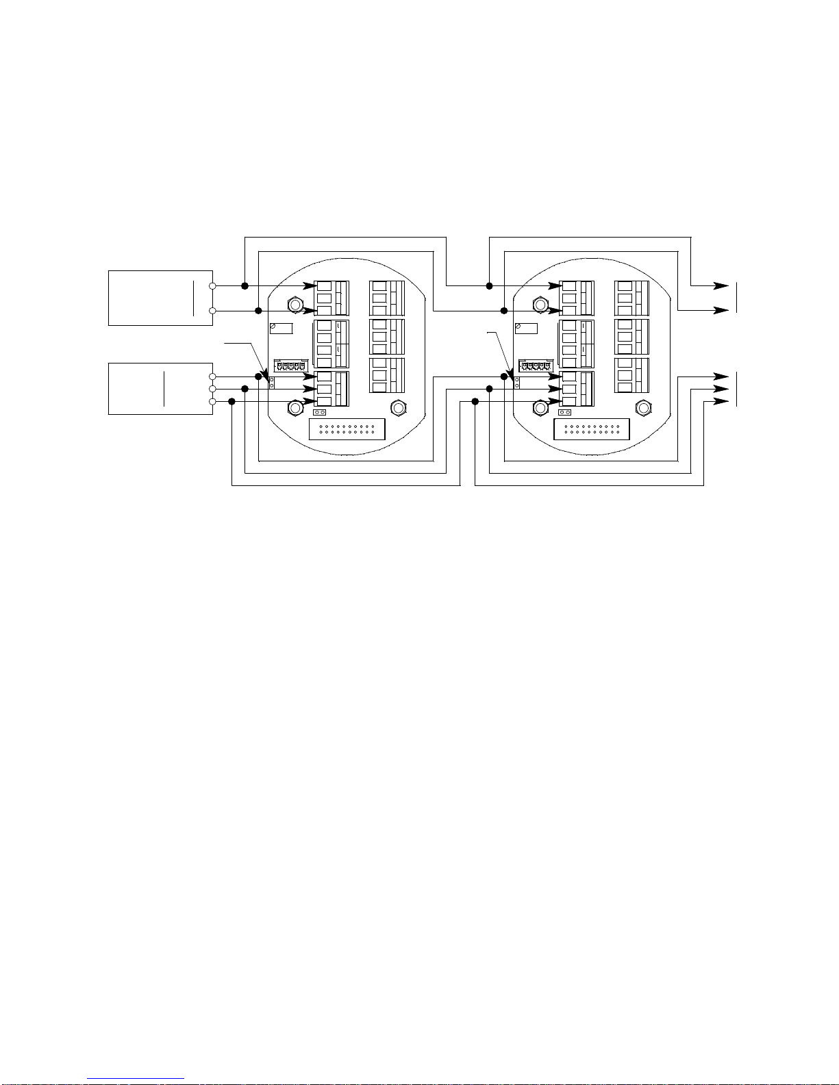
wired into one as shown in Figure 11, the ground jumper should be installed. If the M2A is
+
PWR/SIG
- S +
+
- S +
PWR/SIG
RS 485
A B C
A B C
RS 485
Power Supply
Remov e Ground Jumper
10-30 VDC
-
+
Modbus Controller
Input
Terminals
D0
D1
Common
TOXIC OXY
+
TOXIC OXY
Remove
Ground
Jumper
To
Additional
M2As
C NC NO
ALARM 1
C NC NO
ALARM 2
C NC NO
FAIL
See
Detector
Wiring
C NC NO
ALARM 1
C NC NO
ALARM 2
C NC NO
FAIL
+
See
Detector
Wiring
wired in a Modbus system as shown in Figure 10, the ground jumper should be removed.
Recommended Modbus Wiring
The recommended Modbus wiring for the M2A is illustrated in Figure 10 below. In this
configuration, 5 wires are used for wiring the M2A into a Modbus system. Figure 10 also
illustrates typical alarm device wiring. The ground jumper must be removed in this
wiring configurati on.
Figure 10: Recommended Modbus Wiring
Adding an M2A to an Existing M2 Modbus Installation with Recommended Wiring
An M2A can be wired into an existing M2 Modbus system. The shape of the terminal PCB
will be different but the wiring connections are identical a nd the gro und jumper on the
M2A must still be removed.
65-2643RK-05-04 M2A Transmitter Operator’s Manual 38
Page 44
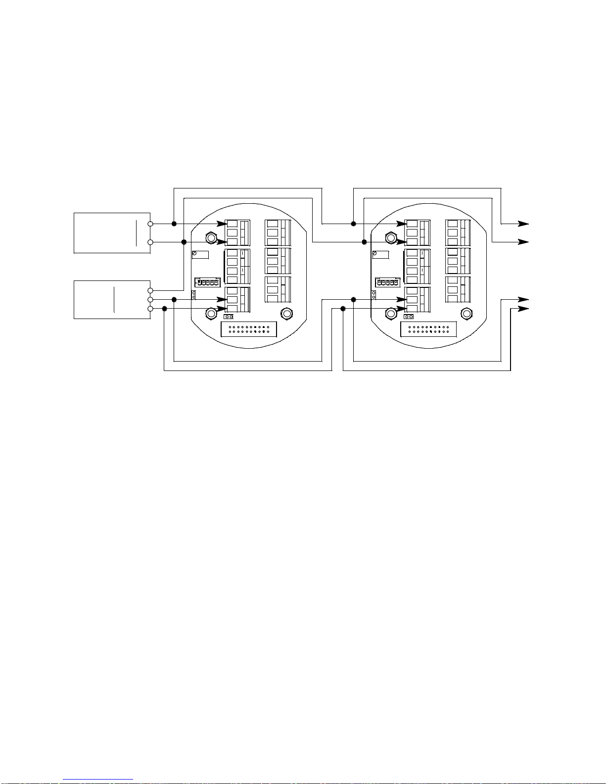
Alternate Modbus Wiring For Existing Installations
PW R/SIG
- S +
+
PW R/SIG
- S +
+
RS 485
A B C
RS 485
A B C
Power Supply
10-30 VDC
-
+
D0
Common
To
Additional
M2As
C NC NO
ALARM 1
C NC NO
ALARM 2
C NC NO
FAIL
See
Detector
Wiring
C NC NO
ALARM 1
C NC NO
ALARM 2
C NC NO
FAIL
D1
Modbus Controller
Input
Terminals
TOXIC OXY
+
TOXIC OXY
+
See
Detector
Wiring
Although the wiring shown in Fi gure 10 is recommended, it is possible to wire the M2A
into a Modbus system with only 4 wires in situations where a pre-existing system is being
replaced and wiring is already in place. This should only be done if wiring for a system
that is being replaced is already installed and it is no t practical to run another wire. See
Figure 11 below for this wiring configuration. In this configuration, the wire between the
“C” terminal on the M2A and the Common terminal on the Modbus controller is omitted.
Instead, the Common terminal on the Modbus controller is connected to the “-” of the 24
VDC power supply. The ground jumper must be installed in this wiring configuration.
Figure 11: Alternate Modbus Wiring
Adding an M2A to an Existing M2 Modbus Installation with Alternate Wiring
An M2A can be wired into an existing M2 Modbus system. The shape of the terminal PCB
will be different but the wiring connections are identical a nd the gro und jumper on the
M2A must still remain installed.
39 65-2643RK-05-04 M2A Transmitter Operator’s Manual
Page 45
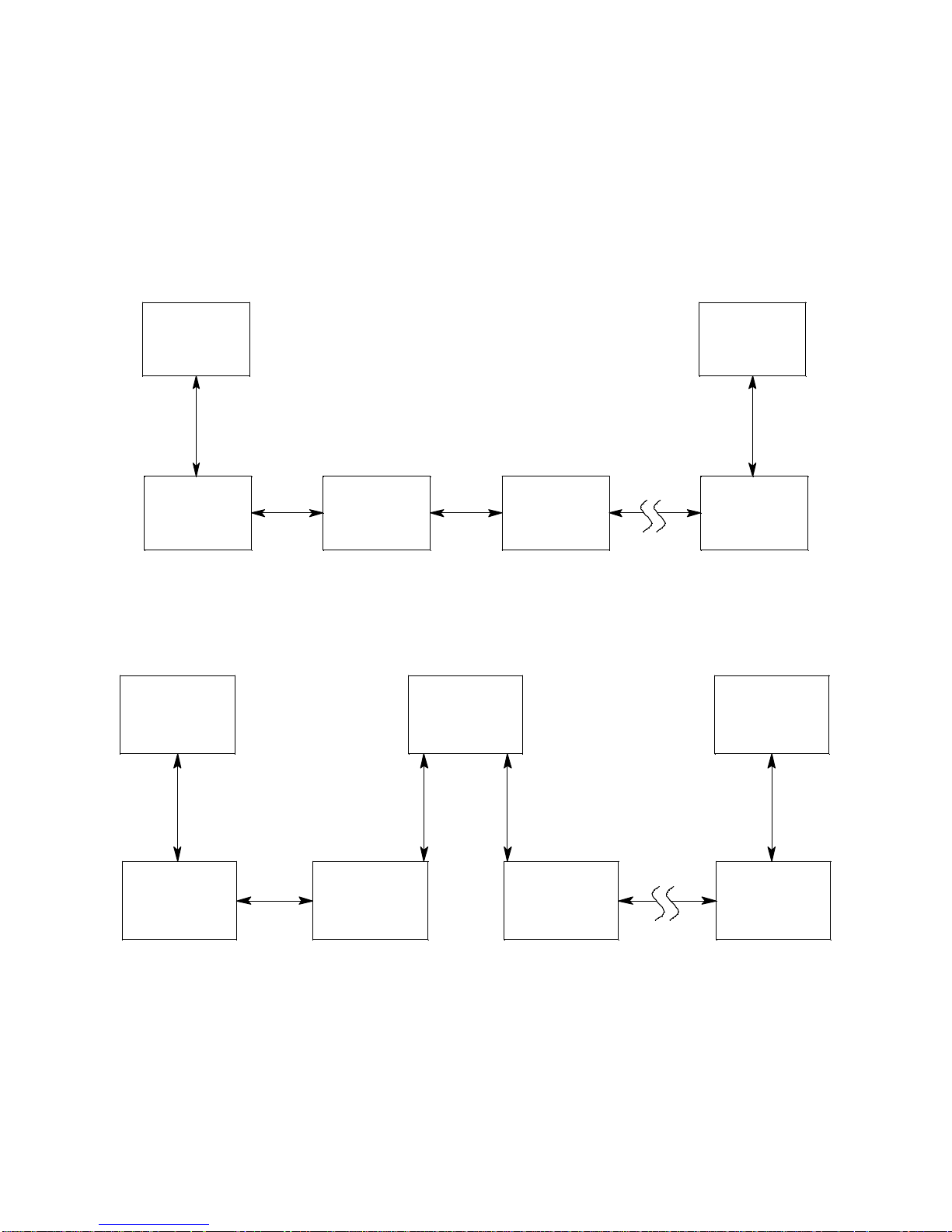
Termination Jumper
ID = 125
Modbus
Master
Up t o 128 M2Ascanbe c onnected without a repeater
RS-485 RS-485
M2A
Termination
Jumper
Not Installed
M2A
Terminat ion
Jumper
Not Installed
ID = 127 ID = 126
M2A
Terminat ion
Jumper
Installed
ID = 128
M2A
Terminat ion
Jumper
Not Installed
M2A
Termination
Jumper
Not Installed
ID = 1
ID = 4
ID = 127
M2A
Termination
Jumper
Installed
RS-485
ID = 128
Up to 128 M2As can be connected without a repeater
Modbus
Master
M2A
Termination
Jumper
Not Install ed
M2A
Termination
Jumper
Not Install ed
M2A
Termination
Jumper
Not Installed
M2A
Termination
Jumper
Not Install ed
ID = 3ID = 2
M2A
Termination
Jumper
Installed
ID = 1
RS-485
The M2A includes a 2-pin termination header (see Figure 4 on page 7) that is used when
the M2A is used in a Modbus system. Every M2A is supplied with a termination jumper
(a jumper block) installed onto this header. If the M2A is not used in a Modbus system,
this jumper has no function. When the M2A is installed in a Modbus system, this jumper
must be installed in an M2A that is at the end of a Modbus line. Any M2A in a Modbus
system that is not at the end of a line must have the terminatio n jumper removed (see
Figure 12 & Figure 13 below).
Figure 12: Multiple M2As in a Daisy Chain Configuration
65-2643RK-05-04 M2A Transmitter Operator’s Manual 40
Figure 13: Multiple M2As in a Two Branch Configuration
Page 46

Using the M2A in a 4-wire Modbus System
Set Up
Modbus?
Although the M2A is a 2-wire Modbus RTU device, it can be used with a 4-wire Modbus
controller if the system wiring is modified as follows:
• Connect the controller’s TxD0 and RxD0 wires together and use this connection as the
2-wire Modbus D0 signal.
• Connect the controller’s TxD1 and RxD1 wires together and use this connection as the
2-wire Modbus D1 signal.
• Connect these D0 and D1 signals and the common wire from the controller to the 2wire Modbus Network of M2As.
Modbus Mode
Modbus Mode allows you to configure various parameters relating to the Modbus setup
of the M2A. Modbus Mode includes a 5-minute time-out feature. If you do not press a
control button for 5 minutes, the M2A autom atically returns to normal operation.
NOTE: If the M2A returns to normal operation because of a time-out, it enters a warm-
up period just as it does when it is first turned on.
1. While in normal operation, simultaneously press and hold the DOWN/NO and
ENTER buttons for 5 seconds to enter Modbus Mode. Release the buttons when the
following screen appears.
2. To exit Modbus Mode, press and release the DOWN/NO button. The M2A will return
to normal o peration.
To continue in Modbus Mode, press and release the UP/YES button. The current
ENABLED/DISABLED setting will appear.
3. If you want to change the currently displayed parameter, use the UP/YES and
DOWN/NO buttons to adjust it to the desired setting, then press ENTER to continue
to the next parameter.
If the currently displayed parameter setting is OK, press the ENTER button to proceed
to the next parameter.
Table 9 lists the M2A Modbus Mode parameters you can set. Table 9 also lists the
factory set value for each parameter.
41 65-2643RK-05-04 M2A Transmitter Operator’s Manual
Page 47

Table 9: Configuration Parameters
Modbus Mode Parameter Available Settings & Description
Enabled/Disabled Can be set to ENABLED or DISABLED (factory setting).
Enables or disables the Modbus output.
Slave ID The Slave ID can be set to values from 1 (factory setting) to 247.
The M2A will only receive messages from the Master which are
addressed to this Slave ID (except for broadcast messages which
are received by all slaves).
Baud Rate Can be set to 1200, 2400, 4800, 9600 (factory setting), 14440, &
19200.
Parity EVEN (factory setting), ODD, NONE
Response Delay The response delay can be set from 0 (factory setting) to 20 mS.
This is an optional additional de lay inserted by the M2A prior to
returning a response message to the Master. It may be helpf ul in
some installations where the Master’s preparedness to receive
responses might be delayed.
4. When you have scrolled throug h all the adjustable parameters, SAVE IT? YES/NO
appears on the display.
5. If you do not wish to save the adjustments, press and release the DOWN/NO button.
The DO OVER? YES/NO message will display. Press and release the DOWN/NO
button. The ABORT? YES/NO message will display. Press the UP/YES button to
return to normal operation.
If you wish to change some of the adjustments made, press and release the DOWN/
NO button. The DO OVER? YES/N O message will display. Press and release the UP/
YES button. The Re-do MB Setup message will display and the M2A will return to
the first adjustable parameter. Go back to step 3 and continue.
If you want to save the adjustments made, press and release the UP/YES button.
Modbus Saved is indicated on the display for a few seconds and the M2A returns to
normal operation.
NOTE: All M2As on a Modbus network must be configured with the same baud rate
and parity, and each M2A must have a unique slave ID. For an M2A to
participate on a network, the ENABLED/DISABLED setting must be set to
ENABLE.
65-2643RK-05-04 M2A Transmitter Operator’s Manual 42
Page 48
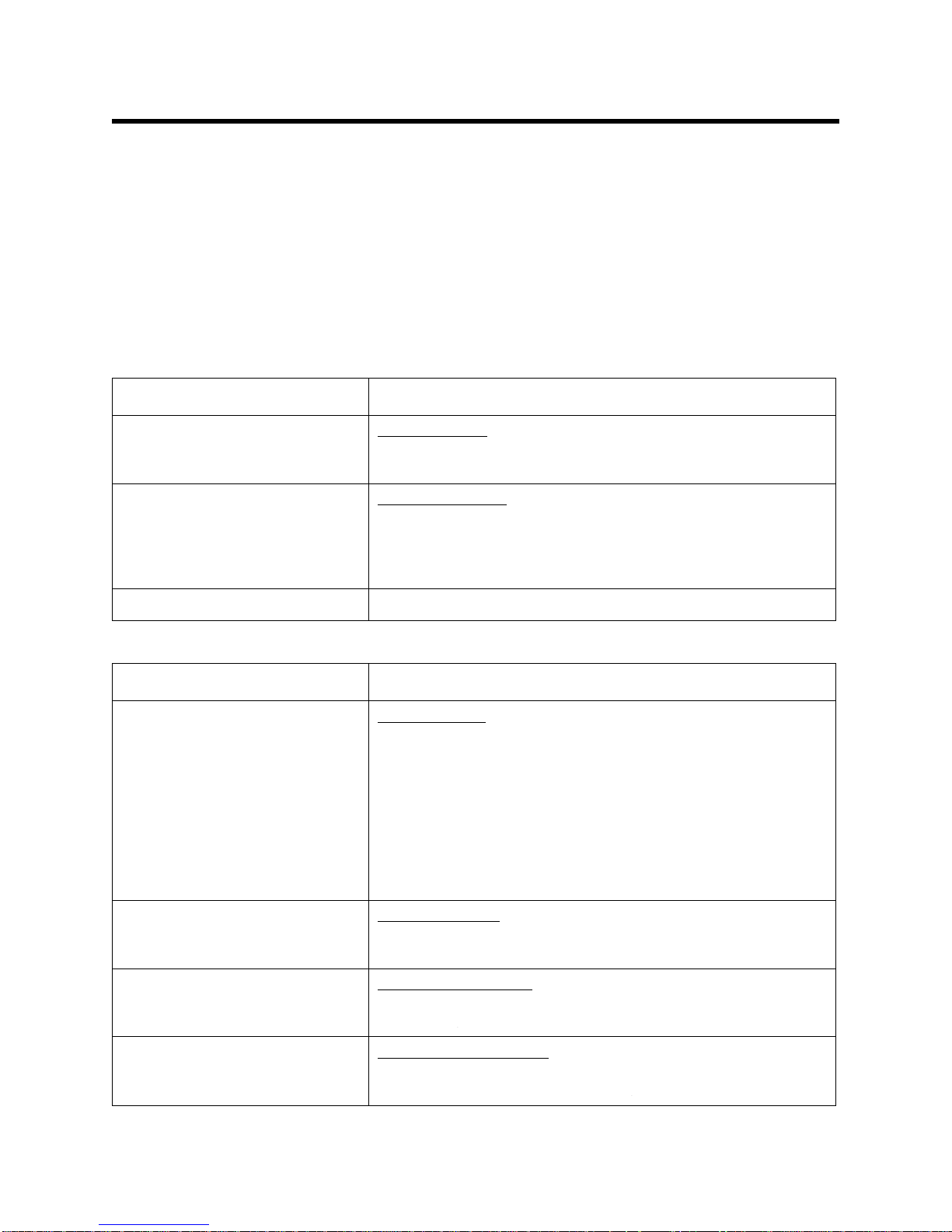
Supported Modbus Functions
The M2A supports Function Code 03: Read Holding Registers and Function Code 16:
Write Registers.
Function Code 03: Read Holding Registers
There are a total of 40 registers available to be read via this Function Code.
Registers 1 - 2
The format (bit & field assignments) for registers 1 - 2 is shown below in Table 10 Table 11.
Table 10: Register 1, Numerical Reading with Sign & Decimal Point Bit & Field Assignments
Bit(s) Value & Field
[15] Sign of Reading
0 = Positive
1 = Negative
[14:13] Format of Reading
0 = XXX (no decimal point)
1 = XX.X
2 = X.XX
3 = .XXX
[12:0] Numerical value of display readin g (8000 max)
Table 11: Register 2, Operating State, Alarms & Relays Bit & Field Assignments
Bit(s) Value
[15:12] Operating State
0 = Undefined
1 = Initialization
2 = Normal
3 = Warm-up
4 = Fail
5 = Calibration
6 = Post-Calibration
7 = Low Power
8 = Setup
[11] Gas Type Change
0=Not Changed
1=Changed
[10] Configuration Change
0=Not Changed
1=Changed
[9] Calibration Activity Flag
0=No Calibration Activity
1=Calibration Activity Has Occurred
43 65-2643RK-05-04 M2A Transmitter Operator’s Manual
Page 49

Table 11: Register 2, Operating State, Alarms & Relays Bit & Field Assignments (Continued)
Bit(s) Value
[8] Fail Status
0 = Fail Not As serted
1 = Fail Assert ed
[7:6] Alarm 2 Status
0 = No Alarm
1 = Unacknowle dged Alarm
2 = Acknowledged Alarm
3 = Unused Code
[5:4] Alarm 1 Status
0 = No Alarm
1 = Unacknowle dged Alarm
2 = Acknowledged Alarm
3 = Unused Code
[3] Overscale Status
0 = Not Overscale
1 = Overscale
[2] Fail Relay Status
0 = Not Energized
1 = Energized
[1] Alarm 2 Relay St at us
0 = Not Energized
1 = Energized
[0] Alarm 1 Relay St at us
0 = Not Energized
1 = Energized
Register 3
Register 3 is the supply voltage (0.1 volt per count).
Registers 4 - 11
The 16 bytes in these registers contain the sa me ASCII text information that is displayed
on the M2A’s OLED display (not NULL Terminated).
Register 12
Register 12 is the range (full scale readout).
Register 13
Register 13 is t he alarm 1 set point.
The decimal point location is the same as specified in Register 1.
Register 14
Register 14 is t he alarm 2 set point.
The decimal point location is the same as specified in Register 1.
65-2643RK-05-04 M2A Transmitter Operator’s Manual 44
Page 50

Registers 15 - 19
Registers 15 - 19 are the Gas Name ASCII String (NULL Terminated).
Registers 20 - 22
Registers 20 - 22 are the Gas Units String (NULL Terminated).
Register 23
Register 23 is t he alarm 1 trigger.
0=Decreasing
1=Increasing
Register 24
Register 24 is the alarm 1 normal relay state.
0=Normally De-Energized
1=Normally Energized
Register 25
Register 25 is the alarm 1 relay re set.
0=Latching
1=Self-Resetting
Register 26
Register 26 is the alarm 1 O N delay.
Integer values are in seconds.
Register 27
Register 27 is the alarm 1 OFF delay.
Integer values are in seconds.
Register 28
Register 28 is t he alarm 2 trigger.
0=Decreasing
1=Increasing
Register 29
Register 29 is the alarm 2 normal relay state.
0=Normally De-Energized
1=Normally Energized
Register 30
Register 30 is the alarm 2 relay re set.
0=Latching
1=Self-Resetting
Register 31
Register 31 is the alarm 2 O N delay.
Integer values are in seconds.
Register 32
Register 32 is the alarm 2 OFF delay.
Integer values are in seconds.
45 65-2643RK-05-04 M2A Transmitter Operator’s Manual
Page 51

Register 33
Register 33 is zero suppressi on.
Toxics and LEL: 0%-6% of full scale
Oxygen: 0%-0.7% Oxygen
The decimal point location is the same as specified in Register 1.
Register 34
Register 34 is noise filter.
Integer values in seconds.
0-60 in 5 second increments.
Register 35
Register 35 is calibration timeout in minutes (5, 10, 15, 20, 25, or 30).
Register 36
Register 36 is calibration month (upper byte) and day (lower byte).
This is zero based (e.g. January=0 and the 1st=0).
Register 37
Register 37 is the calibration year.
Register 38
Register 38 is the calibration outcome.
Upper=Gas Operation
Lower=Air Operation
Calibration Outcome Codes:
1=Sensor Missing
2=Sensor Too Weak
3=Signal Too Strong
4=Not Enou gh Span
5=Negative Re ading
6=Span Gas Value Is Not OK
7=Calculated Zero Is Too Low
8=Calculated Zero Is Too High
9=Zero Failure
10=Span Failur e
11=Calibrati on Is Overscale
12=LEL Sensor Offset Is Too High
13=LEL Null Operation Failed
14=Operat ion Not Performed
Register 39
Register 39 is the auto-zero disable.
0=AutoZero Enabled
1=AutoZero D i sabled
Register 40
Register 40 is the remote configuration register access level
0=None
1=Alarm Reset
65-2643RK-05-04 M2A Transmitter Operator’s Manual 46
Page 52

Function Code 16: Write Registers
There are 21 registers in Function Code 16 that can be used to write to the M2A. This
manual only describes Register 16 because it can be used to reset an alarm condition. For a
complete description of Function Code 16, request Appendix C from RKI Instruments,
Inc.
Register 16
Register 16 performs the same function as the ENTER button on the M2A. It is useful for
remotely silencing alarms. With the M2A in an alarm condition, bit [0] can be use d to
silence it.
Table 12: Register 16, Button Function
NOTE: Register 40 in Function Code 03, the remote configuration register, must be set
to 1 in order for Register 16 to work.
Bit Value & Field
[0] ENTER (used for “Alarm Reset”)
0=Not Pressed
1=Pressed
47 65-2643RK-05-04 M2A Transmitter Operator’s Manual
Page 53

Parts List
Table 13 lists replacement parts and accessories for the M2A Transmitter.
Table 13: Parts List
Part Number Description
06-1248RK Calibration kit sa mple t ubing (3/ 16 in . x 5/16 in.; sp ecify le ngt h when or dering )
07-0033RK Detector housing cap gasket
18-0400RK-01 Detector junction box, with spacers
18-0431RK-01 M2A junction box
45-6132RK Termination and ground jumper
65-1025RK Plug-in oxygen sensor
65-2514RK Oxygen detector
71-0387 65-2643RK-05-04 M2A Transmitter Operator’s Manual (this document)
81-0076RK-01 Zero air calibration cylinder, 34 liter steel
81-0076RK-03 Zero air calibration cylinder, 103 liter steel
81-0078RK-01 Calibration cylind e r, 100% nitrogen, 34 liter steel (used for setting oxygen zero)
81-0078RK-03 Cali bration cyl inder, 100 % nitrogen, 10 3 liter steel (used for setti ng oxygen zero )
81-1050RK Regulator, with gauge and knob, 0.5 LPM, for 17- and 34-liter steel cylinders
81-1051RK Regulator, with gauge and knob, 0.5 LPM, for 34-liter aluminum and 58- and
103-liter steel cylinders
81-1116RK Calibration adapter/splash guard
65-2643RK-05-04 M2A Transmitter Operator’s Manual 48
Page 54

Appendix A: Control Button Quick Reference Guide
The M2A’s control buttons allow access to operational modes, resetting of alarms, and
display of the Information Screen. Table 1 4 shows which button combinations perform
these functions and which parameters are available for adjustment while in the
operational modes. While in these modes, display prompts showing a “?” require you to
respond by pressing either the UP/YES (for yes) or DOWN/NO (for no) button. To
change parameter settings, use the UP/YES and DOWN/NO buttons to get the desired
setting, then press and release the ENTER button to accept the setting.
Table 14: Control Button Quick Reference Chart
Mode Entered or
Function Performed
Alarm Reset Press and
Show Information
Screen
Calibration Mode Press and Hold
Configuration Mode Press and Hold
Gas Type Mode Press and Hold
Button
Combination
Release ENTER
Press and Hold
DOWN/NO
UP/YES for 5
seconds
UP/YES &
ENTER for 5
seconds
UP/YES and
DOWN/NO for
5 seconds
Adjustable or Viewable Parameters
n/a
•Input Voltage
• M2A Version/Revision Information
• Fresh Air Adjust
• Span (or Zero for Oxygen) Adjust with
Calibration Gas
• Alarm Levels
• Increasing or Decreasing Alarms
• Normally Energized or Normally Deenergized Relays
• Latching or Self-resetting Alarms
• Alarm On Delay
• Alarm Off Delay (if self-resetting)
•Zero Suppression
• Noise Filter
• Calibration Time-out Period
Gas Type
Modbus Mode Press and Hold
49 65-2643RK-05-04 M2A Transmitter Operator’s Manual
DOWN/NO and
ENTER for 5
seconds
• Enable or Disable Modbus
•Slave ID
•Baud Rate
•Parity
• Response Delay
Page 55

Appendix B: PLC and DCS Device Wiring
The M2A can be wired to a PLC or DCS device if desired.
1. Guide multi conductor sh ield ed cable or cables or wires in conduit through the top
conduit hub of the junction box. The number of cables or wires needed will depend on
whether any relays are used and whether the Modbus output is used. Use the
following recommendations to determine how to wire the M2A:
• If Modbus connections will not be used and only the PWR/ SIG terminal strip
connections will be used, use four conductor shielded cable or four wires in
conduit for connections to the power/signal terminal strip.
Table 15: Wire Size for PWR/SIG Connections
Max Distance to Controller
w/18 Gauge Wire
2,500 ft. 5,000 ft. 8,000 ft.
• If the PWR/SIG terminal strip connections and one or more relays are used, r oute
the connections to the M2A in conduit. Use shielded cable in the conduit for the
PWR/SIG connections and unshielded cable or individual wires for the relay
connections. Make sure any wire or cable used for relay wiring is appropriately
rated for the power that it will carry.
NOTE: If shielded cable is used for the PWR/SIG connections, leave the cable shield’s
drain wire insulated and disconnected at the M2A . You will connect the
opposite end of the cable’s drain wire at the controller or device.
• If the M2A will be wired into a Modbus network, see “Chapter 8: R S-4 85 Modbus
Output” on page 37.
Max Distance to Controller
w/16 Gauge Wire
Max Distance to Controller
w/14 Gauge Wire
65-2643RK-05-04 M2A Transmitter Operator’s Manual 50
Page 56
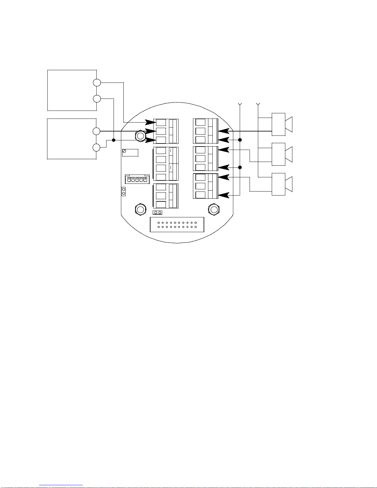
See Figure 14 below for field wiring connections to the M2A.
Fail Alarm
Device
Alarm 1
Alarm Device
- S +
Alarm Device
Power
+
PWR/SIGRS 485
A B C
TypicalAlarm
WiringShown
24 VDC -
24 VDC
Power Supply
24 VDC +
(24 VDC) -
4-20mA In (S)
See
Modbus
Wiring
Controller
(PLC, DCS)
See
Detector
Wiring
TOXIC OXY
+
Alarm 2
Alarm Device
C NC NO
ALARM 1
C NC NO
ALARM 2
C NC NO
FAIL
Figure 14: PLC and DCS Device Wiring
51 65-2643RK-05-04 M2A Transmitter Operator’s Manual
Page 57

Appendix C: Function Code 16 Registers
The M2A supports Function Code 16 that allows writing to the M2A. There are 21
registers in this Function Code.
Register 1
Register 1 is the alarm 1 set point.
Value must be an integer. Any decimals are omi tted.
Register 2
Register 2 is the alarm 1 trigger.
0=Decreasing
1=Increasing
Register 3
Register 3 is the alarm 1 relay state.
0=Normally De-Energized
1=Normally Energized
Register 4
Register 4 is the alarm 1 relay reset.
0=Latching
1=Self-Resetting
Register 5
Register 5 is the alarm 1 ON delay.
Integer value is in seconds.
Register 6
Register 6 is the alarm 1 OFF delay.
Integer value is in seconds.
Register 7
Register 7 is the alarm 2 set point.
Value must be an integer. Any decimals are omi tted.
The decimal point location is the same as specified in Register 1 of Function Code 03.
Register 8
Register 8 is the alarm 2 trigger.
0=Decreasing
1=Increasing
Register 9
Register 9 is the alarm 2 relay state.
0=Normally De-Energized
1=Normally Energized
65-2643RK-05-04 M2A Transmitter Operator’s Manual 52
Page 58

Register 10
Register 10 is the alarm 2 relay re set.
0=Latching
1=Self-Resetting
Register 11
Register 11 is the alarm 2 O N delay.
Integer value is in seconds.
Register 12
Register 12 is the alarm 2 OFF delay.
Integer value is in seconds.
Register 13
Register 13 is the zero suppression.
Toxics and LEL: 0%-6% Full Scale
Oxygen: 0%-0.7% Oxygen
Value must be an integer. Any decimals are omi tted.
Register 14
Register 14 is the noise filter.
Integer value is in seconds (0-60 in 5 second increments).
Register 15
Register 15 is the calibration timeout.
Value is in minutes (5, 10, 15, 20, 25, or 30).
Register 16
Register 16 is explained in “Supported Modbus Functions” in the M2A manu al.
Register 17
Register 17 is the calibration month (MSB) and day (LSB).
This is zero-based (e.g. January=0 and the 1st=0).
Register 18
Register 18 is the calibration year.
Register 19
Register 19 is for clea ring change f lags. Wh en parameters are changed at the M2A, a flag is
raised at the controller. This register can be used to clear those flags.
Table 16: Register 19, Clear Change Flags
Bit(s) Value & Field
[15:2] Unused
[1] Write “1” to this bit to clear “Gas Type Changed” flag
[0] Write “1” to this bit to clear “Configuration Changed” flag
53 65-2643RK-05-04 M2A Transmitter Operator’s Manual
Page 59

Register 20
Register 20 is the AutoZero Disable.
0=AutoZero Enabled
1=AutoZero D i sabled
Register 21
Register 21 is the Remote Configuration Regi ster.
0=No Remote Configuration
1=Reset Alarm
65-2643RK-05-04 M2A Transmitter Operator’s Manual 54
 Loading...