

Three Phase
Voltage Relay
Specifications
Electrical
Line Voltage:
110VAC to 480VAC, 3Ø
Frequency: 50/60Hz
Line Voltage Ranges:
120 Series - 110VAC to 120VAC, 3Ø
208 Series - 208VAC, 3Ø
240 Series - 220VAC to 240VAC, 3Ø
400 Series - 440VAC to 480VAC, 3Ø
Undervoltage:
Adj. to 12% below minimum nominal
Overvoltage:
Adj. to 12% above maxmum nominal
Phase Rotation: A - B - C
Phase Loss:
Complete loss to 65% of nominal
Overvoltage Protection (Max.):
120 Series - 150VAC
208 Series - 300VAC
240 Series - 300VAC
400 Series - 550VAC
Drop-out Delay: 0.2 sec., fixed
Power Consumption: 2VA
Ordering Information
PVM - 240A - 200P
R-K Model
3Ø Input Voltages
120A - 110 to 120VAC
208A - 208VAC
240A - 220 to 240VAC
480A - 440 to 480VAC
Note: PVM-240A-400P covers 208 to 240VAC (Adj. Code "400P" only)
Connections
The PVM-Ps should be connected
to the line voltage on the load side of the
last line fuse before the motor and on the
line side of the starter (MS).
M = Motor
MS = Motor Starter
OL = Overloads
Fuses = ≤1 amp (optional)
L1
L2
L3
3
2
Start
Stop
MS
4 5
1
MS
OL
Fuses
6
7
8
OL
MS
Output Contacts:
5 Amps @ 240VAC
125VA @ 120/240VAC
100,000 Full Load Cycles
10,000,000 Mechanical Cycles
Physical
Mounting: Plug-In
Termination: 8 Pin
Packaging: Dust Cover
Weight: 4.5 oz. Approx.
Ambient Temperatures
Operating: 0°C to 65°C
U.L. Operating: 0°C to 40°C
Storage: -30°C to 85°C
Sockets
120 thru 240 Series:
IDEC: SR2P-05, SR2P-06
480 Series:
Custom: OT08
Adjustments
100P - Fixed
(Specify Voltages)
200P - Adjustable
400P - Undervoltage Only
De-Energized
Energized
De-Energized
Dimensions
M
3.2"
.5" 1.8"
Overvoltage
Undervoltage
2.4"
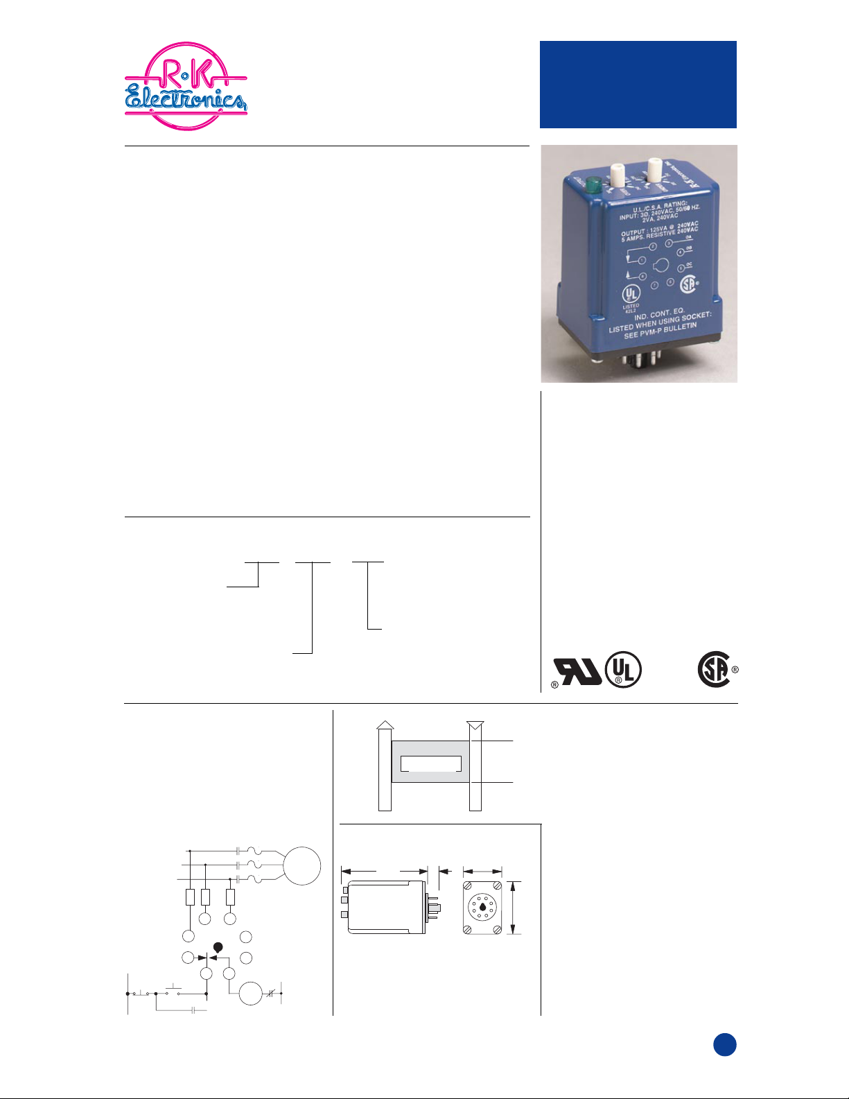
PVM-P
• Plug-In Package
• Adj. Overvoltage
• Adj. Undervoltage
• Phase Loss
(Single Phasing)
• Phase Rotation
• Status LED
• Drop-Out Delay
• Automatic Reset
• 240 Volt Control
Contact Rating
• 5 Amp, SPDT
with
appropriate
socket
Operation
The PVM-P’s output contacts
energize when:
1. All the phases are present;
2. The voltages are within set points;
3. The phases are in proper rotation.
If any of these conditions shift
beyond the setpoints, the output
contact will de-energize after a .2
second fixed time delay period.
Single phase conditions will only be
detected if there is a substantial loss
of voltage in one phase. In some
applications, motors that continue to
rotate after the loss of a phase may
re-generate voltages that simulate
the line conditions. Consider R-K’s
PVC or PVR series if loss of phase
is critical in your applications.
6/25/00
T6
 Loading...