

Page 1

The PDC has been designed to operate as an alternating Duplex Pump Down
Controller with high alarm. The PDC also has the capability of sensing one or two
damaged fl oat switches and adjusting its operation accordingly.
When the level rises above the “Cut-Off” fl oat, the input closes to the PDC, the LED
is illuminated, but no pump outputs are initiated. As the level continues to rise above
the “Lead” fl oat, the LED is illuminated and the output contact to start pump #1 is
closed. If the level begins to lower below the “Lead” fl oat, the “Lead” fl oat LED goes
out, but pump #1 continues to run until the “Cut-Off” fl oat opens. This is the end of a
pumping cycle.
Since a pumping cycle has been completed, the PDC will automatically switch the
lead pump to pump #2 (Alternating Operation). This provides for distributed running
time on both pumps, helps to ensure that the impellers are cleared periodically and
the seals are wetted, extending the life of the pump.
Normally Open (NO) contact
or Solid State (NPN)
5 Sec., Fixed
5 Sec., Fixed
DuplexPump Down
115A
- 115VAC
230A - 208 to 230VAC
4.280"
2"
3.479"
4.158"
3.75"
0°C to 65°C
C
1
2
4
Inputs
Contact
Load
Voltage
Alarm
Voltage
AL2L1
1 2 3 4C
Input
Voltage
1 2 A
Output
Contacts
3
3
S
Operation
Controller with High Alarm
PDC
• Pump Down
• De-Bounced Inputs
• High Alarm Output
• Lost Input
Compensation
• Removable T
Blocks
• Low Level Cut-Off
erminal
Specifi cations
Electrical
• Staggered Starting
• Indicating LEDs
• Manual or Auto
Alarm Reset
Physical
• Float Sequence Error
Alarm
Ambient Temperatures
Ordering InformationDimensions
Connections
•
11/25/02
P9
Page 2
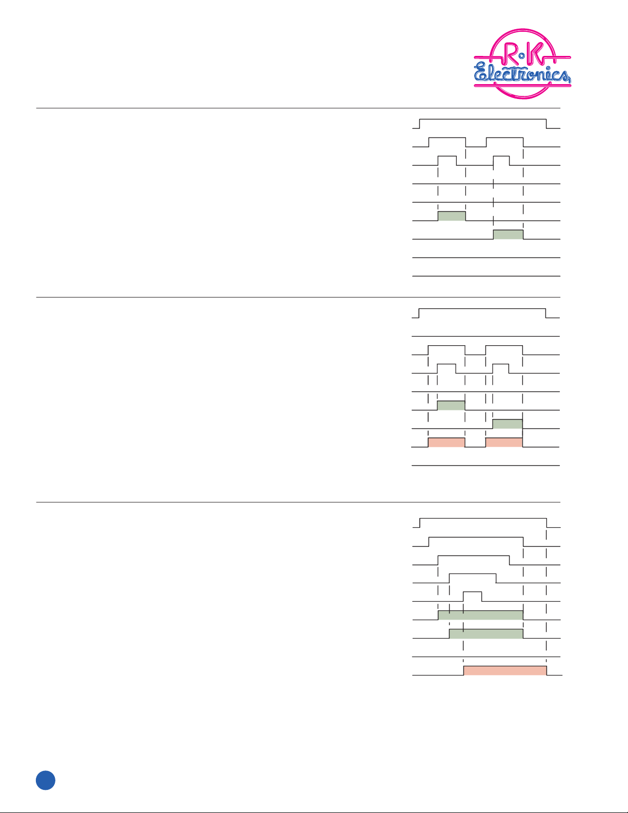
Duplex Pump Down
Input Voltage
Cut-Off Float
Lead Float
Lag Float
High Alarm Float
Pump #1
Pump #2
Sequence Error
High Alarm
Input Voltage
Cut-Off Float
Lead Float
Lag Float
High Alarm Float
Pump #1
Pump #2
Sequence Error
High Alarm
Input Voltage
Cut-Off Float
Lead Float
Lag Float
High Alarm Float
Pump #1
Pump #2
Sequence Error
High Alarm
PDC
Normal Operation:
Lost Cut-Off Float Operation:
Controller with High Alarm
High Alarm Operation:
P10
11/25/02
•
 Loading...