

Page 1
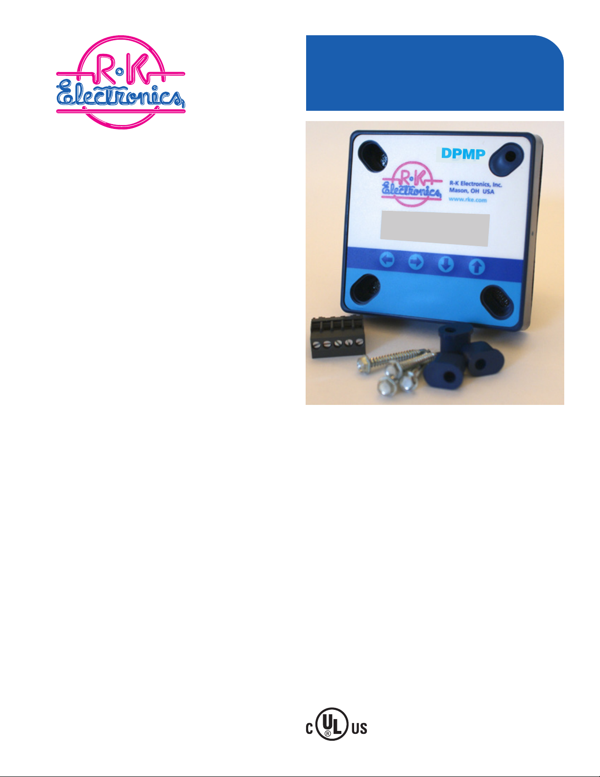
DPMP
DPMP
L1 L2 L3
460 460 460 ON
Digital Phase
Monitor
Digital Voltage Monitor
Panel Mounting (On the Door)
Single & Three Phase
200-240VAC, Single Phase
200-600VAC, Three Phase
All Digital Settings
11.16.16
Page 2

Purpose
The purpose of the DPMP is to
monitor the line voltage supplying single and three phase
systems, providing the opportunity to disconnect equipment if the voltages are outside
of the selectable operational
parameters.
Operation
If the voltages and rotation are
within the selectable set-up
parameters, the DPMP will energize the internal relays, transferring the output contacts. If
the voltages and/or rotation
are outside any of the set-up
parameters, the DPMP internal
relays will not energized.
If the line voltage does not
meet all of the set-up parameters, the Default screen will
toggle between the voltage
screen showing the actual
voltages and words describing
the fault.
During transitions to relays energized or relays de-energized,
the remaining time in seconds
is displayed above the present
relay condition (“ON” or “o”).
General Operational Specications
Line Voltages Monitored: 200 to 240VAC, 1Ø, 50/60Hz
200 to 600VAC, 3Ø, 50/60Hz
Faults: Overvoltage
Undervoltage
Phase Loss
Phase Rotation
Phase Imbalance
Frequency Out of Range
Set-Up: Membrane Buttons & Digital Display
• Nominal Line Voltage
• Over/Undervoltage percentage (7% to 15%)
• Trip Time Delay (2 seconds to 10 seconds)
• Re-Start Time Delay (Manual Reset to 4 minutes)
• Phase Imbalance Percentage (3% to 10%)
Screens: Manufacture Name and Firmware Version
Average Voltage, Frequency, Imbalance, Relay Status
A-B, B-C & C-A Voltages, Relay Status
Nominal Voltage Selection
(Pay attention to 1Ø and 3Ø at the end of the voltages)
Over/Undervoltage Percentage Selection
Trip Time Delay
Re-Start Time Delay
Phase Imbalance Percentage Selection
History with Last 4 Faults
(Wraps back to Manufacture Name and Firmware Version)
Default Set-Up
The default set-up for the DPMP as shipped from R-K Electronics is:
Line Voltage: 480VAC, 3Ø
Over & Undervoltage: ±5%
Trip Time Delay: 5 seconds
Re-Start Time Delay: 5 seconds
Phase Imbalance: 5%
Custom Set-Up
The DPMP uses 4 membrane buttons to allow the customer to change the set-up
criteria for their particular line voltage and preferred parameters. The following
listings show the arrangement and selections available by moving through the
menu choices. The membrane buttons allow for movement right or left with
wrap around to selection criteria and up and down within a selection for specic
parameters.
You can select the set-up parameters with only the supply voltage connected.
Example: From the Default screen (A-B, B-C & C-A voltages with relay status)
pressing the right Arrow will take you to the line voltage selection parameters. If
you want to change the nominal voltage to a dierent voltage, press the Up or
Down arrows. Once you have the line voltage (and number of phases) that you
want displayed on the screen:
1. Pressing either the Right or Left arrow will set the new line voltage parameter
into memory and take you to the next screen, or
2. After 30 seconds of no action, the new voltage parameter will be set into
memory and the screen will go back to the default screen.
2
Page 3

Example: If you want to change the Re-Start Delay to 3 minutes (default is 5 seconds)
and you are on the Default screen:
1. Press the Right arrow until you get to the Re-Start Delay screen
2. Press the Up button until you have 3 Minutes on the screen
3. Pressing either the Right or Left arrow will set the new Re-Start Delay into memory
and take you to the next screen, or
4. After 10 seconds of no action, the new Re-Start Delay will be set into memory and
the screen will go back to the Default screen.
Screens
Manufacturer’s Screen
R-K Electronics
DPMP v0.0.00
Average Voltage Screen
VAvg Imb Hz
460 0 60 o
Default –
The Default screen shows the real time voltage detected on each of the 3 phases:
A-B B-C C-A
460 459 461 ON
Voltage Selection Screen (Vertical Format)
200, 1Ø; 208, 1Ø; 220, 1Ø; 230, 1Ø; 240, 1Ø;
200, 3Ø; 208, 3Ø; 220, 3Ø; 230, 3Ø; 240, 3Ø; 380, 3Ø; 415, 3Ø; 440, 3Ø;
460, 3Ø; 480, 3Ø; 575, 3Ø; 600, 3Ø;
Over/Undervolage Percentage Screen (Vertical Format)
7%, 8%, 9%, 10%, 11%, 12%, 13%, 14% & 15%
Trip Time Delay Screen (Vertical Format)
2S, 3S, 4S, 5S, 6S, 27S, 8S, 9S & 10S
Re-Start Time Delay Screen (Vertical Format)
Manual, 2S, 3S, 4S, 5S, 6S, 7S, 8S, 9S,10S, 30S, 1M, 2M, 3M & 4M
Phase Imbalance Percentage Screen (Vertical Format)
3%, 4%, 5%, 6%, 7%, 8%, 9% & 10%
Fault Screen (Vertical Format)
“0” most recent fault, “1” previous fault, “2” third oldest fault & “3” fourth oldest fault
Fault words:
“Phase A Loss” (There is no voltage sensed on 3-L1/S)
“Voltage Low” (Average line voltage is less than selected Undervoltage percentage)
“Voltage High” (Average line voltage is more than selected Overvoltage percentage)
“Imbalance” (One Phase is lower than the average voltage by more than
the Imbalance percentage)
“Phase Loss” ( One phase is more than 30% below the Line Voltage selection)
“Bad Rotation” (The phase rotation sequence is reversed)
“Bad Freq” Line frequency out of allowable range of 45 to 65Hz)
3
Page 4

DPT
Digital
P
ercentage Timer
Specifications
Electrical
Supply 'Voltage:
24VAC, 120VAC & 240VAC, 1Ø
Frequency; 50/60Hz
Display: 16 Character, 2 Line, LCD
Back Lighting
Adjustments:
Membrane Buttons & Display
Total Cycle Times: 15 & 30 Min
On Tme Percentages:
5% to 95%, 5% Increments
Manual: On or Off
Running Hours:0 to 99,999 Hrs.
Output Rating @ 25°C:
10 Amps @ 120VAC
6 Amps @ 277VAC
1/8 HP @ 120/277 VAC
5 Amps @ 30 VDC
• Digital Dispaly:
- R
emaining Time
- Time & Percentage
Settings
- Running Hours
- Output Relay Status
• Multiple Mounting
Dimensions
• SPDT Contacts
• Gasketed Cover
DPT - 120A - 15/30 -
Supply Voltage
24A - 24VAC
1
20A - 120VAC
240A - 240VAC
Special
xxxx - Special
The DPT is a Digital PercentageTimer.
Operational information is displayed for
easy viewing: tiime remaining till relay
transfer, relay status, running hours &
set-up parameters.
With the supply voltage active, The DPT
will activate the relay output for the
percentage of time selected in set-up.
For total cycle time, you can select either
15 or 30 minutes. On time can be
selected in 5% increments for 5% to
95%.
Manual selection of either continuous On
or Off is available.
Running hours are accumulated based
on the output relay being energized.
Operation
Physical
Mounting: Panel Mounting
4 - Inserts for 2 mounting dim
Termination: Pluggable Block
Packaging: Gasketed Face
Weight: 1 Pound
Am
bient:Temperatures:
Operating : -20°C to 60°C
Storage: 40°C to 85°C
Dimensions
Connections
Ready to
Submit
Timing
1
5/30 - 15 & 30 Minutes
Gasket
Supply
Voltage
NOCNC
MS
.
.
Listed
42L2
Specications
Supply Voltage: 24VAC, 120VAC or 208/240VAC, 1Ø
Part Number:
12 VDC Supply: DPMP-12D-B
24 VDC Supply: DPMP-24D-B
24 VAC Supply: DPMP-24A-B
120 VAC Supply: DPMP-120A-B
240 VAC Supply: DPMP-240A-B
Display: 16 Character, 2 line; Back Lighting
Voltage Accuracy: Approx ±1%
Buttons: (4) Right & Left, Up & Down
Line Voltage Ranges: 200 to 240VAC, 1Ø
200 to 600VAC, 3Ø
Frequency Range: 45 to 65Hertz for all voltages
Over & Undervoltage: 8% to 15%
Phase Imbalance: 3% to 10%
Phase Loss: ≥30% low voltage in any one phase
Phase Rotation: A-B-C
Re-Start Time Delay: 1 second to 4 minutes
Manual Reset Option
Trip Time Delay: 1 second to 30 seconds
Output: SPDT Contact, 10A @ 120VAC
Mounting: Panel Mounting
Body: 2-7/8” Circular Hole (2-1/2” conduit punch)
Holes: (4) Mounting Holes, #10
Termination: Pluggable Terminal Blocks
Packaging: Approx. 3.88”H x3.88W x3.6”D (Front to back of terminal blocks)
Nema 12
Dimensions
L1 L2 L3
460 460 460 ON
3.88"
Connections
L1
L2
L3
L3
NC
L2
DPMP
L1
NO
0.71"
MS
2"
2.9" 2.81"
2.875"
L1
L2
3.88"
.88"
L3
L1
L2
NC
NO
0.2" Dia.
2.5"
2.5"
2.81"
MS
3" Dia.
2.875"
–
Supply
Voltage
+
MS
4
–
Supply
Voltage
+
MS
 Loading...