

Page 1

IM9000F02-E2
REX-F9000
Communication
Instruction Manual
RKC INSTRUMENT INC.
®
High Resolution
Temperature Controller
Page 2

All Rights Reserved, Copyright ¤ 1999, RKC INSTRUMENT INC.
.
z
MELSEC : MITSUBISHI product
z
C200HS: OMRON product
z
Company names and product names used in this manual are the trademarks or registered trademarks of
the respective companies.
Page 3
IM9000F02-E2
i - 1
Thank you for purchasing the RKC product.
Before operating this instrument, please carefully read this manual and fully understand its contents.
And always keep it around you to make it available easily anytime.
SYMBOL
: This mark is used when careful operation or handling is especially needed.
: This mark is used when a supplemental description of operation or handling is
needed.
: This mark is used when detailed or related information needs to be referred to.
z
If failure or error of this instrument could result in a critical accident of the
system, install an external protection circuit to prevent such an accident.
z
Do not turn on the power supply until all of the wiring is completed. Otherwise
electric shock, fire or malfunction may result.
z
Use this instrument within the scope of its specifications. Otherwise fire or
malfunction may result.
z
Do not use this instrument in the places subject to flammable or explosive
gas.
z
Do not touch high-voltage blocks such as power supply terminals, etc.
Otherwise electric shock may result.
z
Never disassemble, repair or modify the instrument. This may cause electric
shock, fire or malfunction.
CAUTION
: If there are possible dangers such as electric shock, fire (burns), etc. which may
result in operator's loss of life or injury, precautions to avoid such dangers are
described.
: In case instrument damages may be caused if operating procedures are not
strictly followed, precautions to avoid such damages are described.
: This mark is used when great care is needed especially for safety.
WARNING
!
WARNING
!
Page 4

IM9000F02-E2
i - 2
z
This is a Class A instrument. In a domestic environment this instrument may cause radio
interference, in which case the user is requir ed t o t ake adequate measures.
z
This instrument is protected from electric shock by reinforced insulation.
So please arrange reinfor ced insulation to the wire for input signal ag ainst the wires for
instrument power supply, source of power and loads as far as possible.
z
This instrument is manufact ur ed on the assumption that it is used in the condition of being
mounted on the instrumentation panel. Therefore, take the necessary measures on the
equipment side mounted with this instrument so that the operator or other personnel are
not accessible to high-voltage blocks in this instrum ent such as power supply terminals,
etc.
z
Always observe precautions described in this manual. Otherwise serious injury or accident
may result.
z
Conduct all of the wiring in accordance with the local codes and regulations.
z
Install a protection device such as a fuse, etc. in the power supply, input or output line, if
necessary.
z
Do not allow metal fragment s or lead wire scraps to fall inside this instrument . This may
cause electric shock, fire or malfunction.
z
Firmly tighten each terminal screw at the specified torque. Otherwise electric shock or f ire
may result.
z
Do not place any obstacle around this instrument in order not to impede r adiation of heat.
And do not close ventilation holes.
z
Do not connect wires to unused terminals.
z
Before cleaning the instrument , always turn off the power supply.
z
Remove stains from this instrument using a soft, dry cloth. Do not use a volatile solvent
such as thinner in order to avoid deformation or discolor at ion.
z
Do not rub nor strike the display unit of this instrument with a hard object.
NOTICE
z
This manual is prepared especially for readers who already have a fundamental knowledge of
electricity, control, computer and communication.
z
This manual is subject to change without prior notice.
z
Examples of figures, diagrams and numeric values used in this manual are for a better
understanding of the text, but not for assuring the resultant operation.
z
This manual may not be reproduced or copied in whole or in part without RKC's prior consent.
z
RKC assumes no responsibility for any of the following damage which the user or third party may
suffer.
x Damage incurred as a result of using this product.
x Damage caused by product failure which cannot be predicted by RKC.
x Other indirect damage.
z
In order to use this instrument continuously and safely, periodic maintenance is required. Some of
components and parts used in this instrument have a limited service life, or deteriorate over time.
z
This manual is carefully prepared. However, if any mistake or omission is found, please contact
RKC.
CAUTION
Page 5

IM9000F02-E2
i - 3
CONTENTS
Page
1. SPECIFICATION...................................................................1
2. CONNECTION.......................................................................3
3. SETTING FOR COMMUNICATION ......................................6
3. 1
Preparation for setting communication parameters........................................6
3.2 Transfer to parameter group 24 (PG24) ..........................................................7
3.3 Communication parameter selection...............................................................8
3.4 Device address setting....................................................................................9
3.5 Communication speed setting.......................................................................11
3.6 Communication data configuration setting....................................................13
3.7 Interval time setting.......................................................................................15
3.8 Protocol setting..............................................................................................17
3.9 Cautions for communicatin............................................................................19
4. RKC STANDARD COMMUNICATION................................22
4.1 Communication protocol................................................................................22
4.1.1 Polling...............................................................................................................22
4.1.2 Selecting...........................................................................................................27
4.2 Communication identifier...............................................................................31
5. LADDER COMMUNICATION..............................................36
5.1 Communication protocol................................................................................36
5.1.1 Communication data configuration ...................................................................36
5.1.2 Data format.......................................................................................................38
5.1.3 Data read..........................................................................................................39
5.1.4 Data write.........................................................................................................40
5.1.5 Reversal of read/write data bytes......................................................................41
5.1.6 REX-F9000 no response ..................................................................................43
5.1.7 Example of text sent by PLC.............................................................................43
Page 6

IM9000F02-E2
i - 4
Page
5.2 Communication identifier...............................................................................44
5.3 Example of sequence program .....................................................................46
5.3.1 MELSEC Series (MITSUBISHI)........................................................................46
5.3.2 C200HS (OMRON)...........................................................................................48
6. TROUBLESHOOTING .......................................................50
7. ASCII 7-BIT CODE TABLE.................................................52
Page 7

IM9000F02-E2
1
1. SPECIFICATION
(1) Interface :
Based on EIA standard RS-485
(2) Connect ion m et hod :
2-wire system, half-duplex multidrop connection
(3) Com m unicat ion dist ance :
1 km (max.)
*However, the maximum communication distance varies slightly
with the surroundings such as cables etc.
(4) Synchronous met hod :
Start/stop synchronous type
(5) Com m unication speed :
1200 bps, 2400 bps, 4800 bps, 9600 bps, 19200 bps
(6) Dat a type : RKC standard communication :
Start bit : 1
Data bit : 7 or 8
Parity bit :Unused or Used (Odd number or even number)
Stop bit : 1 or 2
Ladder communication :
Start bit : 1
Data bit : 8 (Fixed)
Parity bit :None
Stop bit : 1
(7) Pr ot ocol : RKC standard communication :
ANSI X3.28 subcategory 2.5, A4
Polling/selecting type
Ladder communication :
Non-protocol type
(8) Er r o r cont rol (Only RKC standard communication) :
Vertical parity (With parity bit selected)
Horizontal parity (BCC check)
(9) Maximum connection : RKC standard communication :
32 sets including a host computer
Ladder communication :
32 sets including a programmable controller
Page 8
1. SPECIFICATIONS
IM9000F02-E2
2
(10) Communication code : RKC standard communication :
ASCII 7-bit code
Ladder communication :
Text : BCD code
Control code : STX(02H), CR(0DH), LF(0AH)
* Code in brackets ( ) are in hexadecimal.
(11) Terminal resister :
100 : or more (Externally connected)
(12) Xon/ Xoff control :
None
(13) Signal logic :
Signal voltage Logic
V (A) > V (B) 0 (Space status)
V (A) < V (B) 1 (Mark status)
Page 9

IM9000F02-E2
3
2. CONNECTION
Up to 32 REX-F9000 including the host computer (or programmable controller [hereinafter, the
"PLC"]) can be connected if multidrop connected by RS-485.
Terminal No. and signal details
Terminal
No.
Signal
name
Name
Signal direction
REX-F9000 Host computer
or PLC
7
SG Signal ground
8
T/R(A) Send data/Receive data
9
T/R(B) Send data/Receive data
WARNING
!
In order to prevent electric shock or instrument failure, turn off power for this
instrument and peripheral equipment before connecting or disconnecting.
Page 10

2. CONNECTION
IM9000F02-E2
4
Connecting method
z
When RS-485 is used as a host computer or PLC interface
It is necessary that a circuit to transfer send and receive be built-in the host computer (or PLC).
SG
T/R
(B)
T/R(A
)
SG
T/R
(B)
T/R(A
)
RD (RXD
)
:
Receive data
SD (TXD
)
:
Send data
Host com
p
uter or PLC
RS-485
SG
T/R
(B)
T/R(A
)
y
y
y
Up to 31
Paired wire
Send/receive
selection signal
Twisted pair wire
(with shield)
*R: Use a terminal resistor with a combin ed resistance of m ore than 100 :.
*R
REX-F9000
REX-F9000
SD (TXD) and RD (RXD): Negative l ogic
7
8
9
7
8
9
z
When RS-232C is used as a host computer or PLC interface
Communication level converter (RS-232C/RS-485) is used.
Communication
level converter
Paired
wire
*R
*R : Use a terminal resistor with a combined resistance of
more than 100 :.
Twisted pair wire
(with shield)
or
PLC communication
module
Host computer
RS-232C
RS-485
REX-F9000
T/R(B)
SG
T/R(A)
T/R(B)
SG
T/R(A)
7
8
9
When the host computer is for Windows 95/NT, use a communication level converter of
the automatic send/receive select type.
Recommended : CD485, CD485/V manufact ur ed by Data Link, Inc. or equivalent.
CAUTION
Page 11

2. CONNECTION
IM9000F02-E2
5
Connection example
z
1-channel type
When up to 32 REX-F9000 controllers including host computer (or PLC) are connected.
or
0 1 2 3029284
Host computer or PLC
BRA-100B-2BRA-100B-2BRA-100B-2
Communicat ion level converter
RS-232C
RS-485
RS-485
RS-485
REX-F9000REX-F9000REX-F9000
Device
address
Host computer or PLC
3
z
2-channel type
For the 2-channel type REX-F9000 controller, set independent device addresses to CH1 and
CH2.
575610
Device
address
or
RS-485
RS-232C
RS-485
CH2CH1
RS-485
BRA-100B-2BRA-100B-2
BRA-100B-2
REX-F9000REX-F9000
REX-F9000
Communi cat ion level converter
Host computer or PLC
5958 6160
325476
Host computer or PLC
For details of the communication level converter and junction branch box
BRA-100B-2
, see
each Instruction Manual.
Page 12

6
IM9000F02-E2
3. SETTING FOR COMMUNICATION
In order to make communication between the REX-F9000 and the host computer (or PLC), it is
necessary to set the device address, communication speed, communication data configuration, interval
time and protocol. Communication settings are made in parameter group 24 (PG24).
3.1 Preparation for setting communication parameters
The setting of parameter group 24 (PG24) can be changed only in control stop mode. Before the
SETUP mode is selected, it is necessary to set the mode selection of "Control RUN/STOP" to
"STOP."
c
Press the MODE key to set the instrument to the mode transfer.
d
Press the MODE key to display "Control RUN/STOP."
e
Press the DOWN key to control is changed from execution
(RUN) to STOP.
:
Bright lighting
: Dim lighting
SET
MODE
MONI CH
CH
PV
SV
SET
MODE MONI CH
CH
PV
SV
SET
MODE MONI CH
CH
PV
SV
Page 13

3. SETTING FOR COMMUNI CATI ON
IM9000F02-E2
7
3.2 Transfer to parameter group 24 (PG24)
c
Press the SET key to set the instrument to the SV setting mode.
d
Press the SET key for more than 5 sec in SV setting mode to set
the instrument to operator set mode.
e
Press the SET key for more than 5 sec in operator set mode to
set the instrument to setup mode.
f
Press the UP key a few times to display "PG24."
:
Bright lighting
: Dim lighting
SET
MODE MONI CH
CH
PV
SV
SET
MODE MONI CH
CH
PV
SV
SET
MODE MONI CH
CH
PV
SV
SET
MODE MONI CH
CH
PV
SV
Page 14
3. SETTING FOR COMMUNI CATI ON
IM9000F02-E2
8
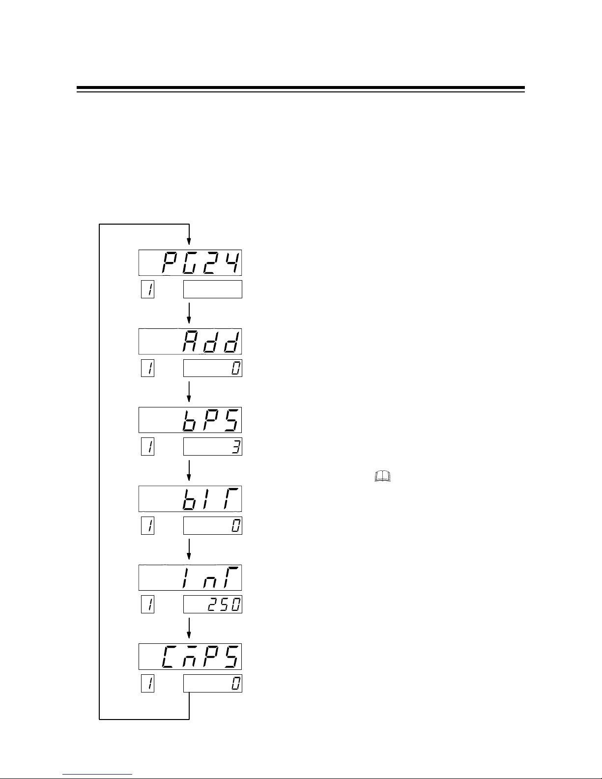
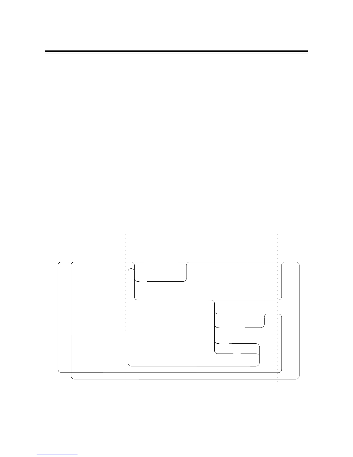
3.3 Communication parameter selection
Communication parameter in parameter group 24 (PG24) are selected in the order of device
address (Add), communication speed (bPS), communication data configuration (bIT), interval time
(InT) and protocol selection (CMPS). Each communication parameter is selected by pressing the
SET key.
Display sequence
In order to set the CH2 monitor,
communication parameter, press
the CH key to change CH1 to
CH2. The setting procedure is
the same as the CH1 setting.
CH
PV
SV
CH
PV
SV
CH
PV
SV
CH
PV
SV
CH
PV
SV
CH
PV
SV
Press the SET key.
Press the SET key.
Press the SET key.
Press the SET key.
Press the SET key.
Press the SET key.
Protocol selection
(CMPS)
Interval time
(InT)
Data configuration
(bIT)
Communication speed
(bPS)
Device address
(Add)
Parameter group 24
(PG24)
Page 15

3. SETTING FOR COMMUNI CATI ON
IM9000F02-E2
9
3.4 Device address setting
Set the desired device address by using the corresponding numeric value from 0 to 99.
Press the UP or DOWN key to change the numeral, and also press the SHIFT key to shift the digit.
Symbol and symbol name
Setting range
Range :
0 to 99
Factory set value :
0
Setting procedure
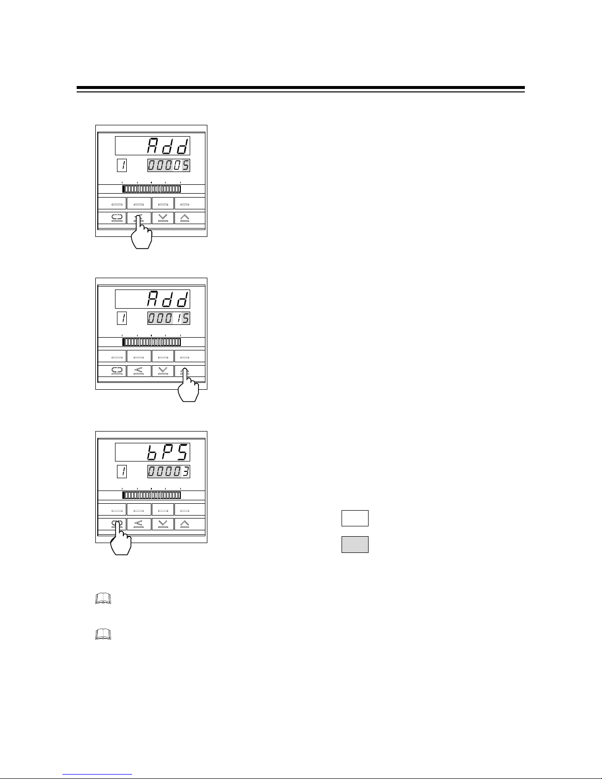
For the 2-channel type REX-F9000, set independent device addresses to CH1 and CH2.
Example :
When setting device address t o 15.
c
Change the controller to parameter group 24 (PG24), and then
display the device address (See P.8).
d
Set the devise address. Press the UP key to enter "5" in the
lowest
digit.
:
Bright lighting
: Dim lighting
SET
MODE MONI CH
CH
PV
SV
CAUTION
SET
MODE MONI CH
CH
PV
SV
(
Add) : Device address
Page 16
3. SETTING FOR COMMUNI CATI ON
IM9000F02-E2
10
e
Press the SHIFT key to brightly light the tens digit.
f
Press the UP key to enter "1" in the tens digit.
g
Press the SET key to select the next communication parameter.
As a result, the set device address is registered.
:
Bright lighting
: Dim lighting
For the 1-channel type, if the key is not operated for more than 1 minute, the present display
automatically returns to the PV/SV display.
For the 2-channel type, if the key is not operated for more than 1 minute, the present display
automatically returns to the CH1PV/CH2PV display.
SET
MODE MONI CH
CH
PV
SV
SET
MODE MONI CH
CH
PV
SV
SET
MODE MONI CH
CH
PV
SV
Page 17

3. SETTING FOR COMMUNI CATI ON
IM9000F02-E2
11
3.5 Communication speed setting
Set a communication speed of 1200 bps, 2400 bps, 4800 bps, 9600 bps or 19200 bps by using
numerals from 0 to 4. Press the UP or DOWN key to change the numeral.
Symbol and symbol name
Setting items
Set value Communication speed Factory set value
0
1200 bps
1
2400 bps
2
4800 bps
3
3
9600 bps
4
19200 bps
Setting procedure
z
Set the same communication speed to both the REX- F9000 and connecti ng host
computer (or PLC).
z
For the 2-channel type REX-F9000, set the comm unicat ion speed t o CH1 and CH2.
Example
: When sett ing communication speed to "2 : 4800 bps."
c Select the communication speed display. (See P.8.)
:
Bright lighting
: Dim lighting
CAUTIONS
SET
MODE MONI CH
CH
PV
SV
(bPS) : Communication speed
Page 18

3. SETTING FOR COMMUNI CATI ON
IM9000F02-E2
12
d
Press the DOWN key to enter "2" in the lowest digit. As a
result,
a communication speed of 4800 bps is set.
e
Press the SET key to change to the next communication
parameter. As a result, the set communication speed is
registered.
:
Bright lighting
: Dim lighting
For the 1-channel type, if the key is not operated for more than 1 minute, the present display
automatically returns to the PV/SV display.
For the 2-channel type, if the key is not operated for more than 1 minute, the present display
automatically returns to the CH1PV/CH2PV display.
SET
MODE MONI CH
CH
PV
SV
SET
MOD MONI C H
CH
PV
SV
Page 19

4. ADJUSTMENT
IM9000F02-E2
13
3.6 Communication data configuration setting
Set the data configuration during communication. Press the UP or DOWN key to change the
numeral.
Symbol and symbol name
Setting items
z
RKC standard communication :
Set the desired numeric value from 0 to 11.
Set value Parity bit Data bit Stop bit Factory set value
0
None 8 1
1
None 8 2
2
Even 8 1
3
Even 8 2
4
Odd 8 1
5
Odd 8 2
0
6
None 7 1
7
None 7 2
8
Even 7 1
9
Even 7 2
10
Odd 7 1
11
Odd 7 2
z
Ladder communication :
The following numeric value is fixed.
Parity bit : None
Data bit : 8
Stop bit : 1
If the protocol is for ladder communication, it becomes invalid even when the communication
data bit configuration is selected.
(bIT) : Communication data configuration
Page 20

3. SETTING FOR COMMUNI CATI ON
IM9000F02-E2
14
Setting procedure
For the 2-channel type REX-F9000, set the same communication data configuration to
CH1 and CH2.
Example
: When setting communication data configuration to "1 : 8 dat a bits, no parity bit
and 2 stop bits."
c
Select the data configuration during communication. (See P.8.)
d
Press the UP key to enter "1" in the lowest digit. As a result,
communication data configuration is set to "8 data bits, no
parity bit and 2 stop bits."
e
Press the SET key to change to the next communication
parameter.
As a result, the set communication data configuration is
registered.
: Bright lighting
: Dim lighting
For the 1-channel type, if the key is not operated for more than 1 minute, the present display
automatically returns to the PV/SV display.
For the 2-channel type, if the key is not operated for more than 1 minute, the present display
automatically returns to the CH1PV/CH2PV display.
CAUTION
SET
MODE MONI CH
CH
PV
SV
SET
MODE MONI CH
CH
PV
SV
SET
MODE MONI CH
CH
PV
SV
Page 21

3. SETTING FOR COMMUNI CATI ON
IM9000F02-E2
15
3.7 Interval time setting
Set the interval time. Press the UP or DOWN key to change the numeral, and press the SHIFT key
to
shift the digit.
Symbol and symbol name
Setting range
Range :
0 to 250 ms
Factory set value :
250
Setting procedure
For the 2-channel type REX-F9000, set the same interval time to CH1 and CH2.
Example :
When setting interval time to 200 ms.
c
Select the interval time display. (See P.8.)
d
Press the SHIFT key to brightly light the tens digit.
:
Bright lighting
: Dim lighting
CAUTION
SET
MODE MONI CH
CH
PV
SV
(InT) : Interval time
SET
MODE MONI CH
CH
PV
SV
Page 22

3. SETTING FOR COMMUNI CATI ON
IM9000F02-E2
16
e
Press the DOWN key to enter "0" in the tens digit.
f
Press the SET key to change to the next communication
parameter. As a result, the set interval time is registered.
:
Bright lighting
: Dim lighting
For the 1-channel type, if the key is not operated for more than 1 minute, the present display
automatically returns to the PV/SV display.
For the 2-channel type, if the key is not operated for more than 1 minute, the present display
automatically returns to the CH1PV/CH2PV display.
SET
MODE MONI CH
CH
PV
SV
SET
MODE MONI CH
CH
PV
SV
Page 23

3. SETTING FOR COMMUNI CATI ON
IM9000F02-E2
17
3.8 Protocol setting
The protocol is selected. Either RKC standard communication or ladder communication is
selected.
Press the UP or DOWN key to change the numeral.
Symbol and symbol name
Setting items
Set value Protocol type Factory set value
0
RKC standard communication
0
1
Ladder communication
Setting procedure
For the 2-channel type REX-F9000, set same prot ocol select ion to CH1 and CH2.
Example :
When setting protocol to "1 : Ladder communication."
c Select the protocol selection display. (See P.8.)
:
Bright lighting
: Dim lighting
CAUTION
SET
MODE MONI CH
CH
PV
SV
(CMPS) : Protocol selection
Page 24

3. SETTING FOR COMMUNI CATI ON
IM9000F02-E2
18
d
Setting a numeric value of "1" by pressing the UP key changes
the protocol to ladder communication.
e
Press the SET key to change to the next communication
parameter. As a result, the set data construction is registered.
:
Bright lighting
: Dim lighting
For the 1-channel type, if the key is not operated for more than 1 minute, the present display
automatically returns to the PV/SV display.
For the 2-channel type, if the key is not operated for more than 1 minute, the present display
automatically returns to the CH1PV/CH2PV display.
SET
MODE MONI CH
CH
PV
SV
SET
MODE MONI CH
CH
PV
SV
Page 25

3. SETTING FOR COMMUNI CATI ON
IM9000F02-E2
19
3.9 Cautions for communication
Send/receive selection
z
When host computer is selected from data sending to data recei ving
When switching the host computer into reception from transmission, it must be confirmed that
the data was surely put on line. This is not observe the transmission buffer of host computer
itself, but confirming with shift register.
Next, the REX-F9000 side secures the maximum time until the transmission line changes to the
data receiving side (until the REX-F9000 is ready to send data) after the host computer has
received the stop bit corresponding to the final character. This maximum time corresponds to
interval time. If no interval time is set, the REX-F9000 side may be set to the send state even
when the host computer side is not set to the receive state. As a result, no communication is
conducted correctly. In addition, set the interval time so as to match the host computer.
z
When host computer is selected from data receiving to data sending
Polling procedure "Response wait time after BCC send" or selecting procedure "Response wait
time after [ACK] or [NAK] send" is processing time required during REX-F9000 data sending.
Therefore, select the host computer from receiving to sending after the lapse of the above time.
As for the necessary processing time, refer to the table of page 21.
Page 26

3. SETTING FOR COMMUNI CATI ON
IM9000F02-E2
20
RS-485 (2-wire system) send/receive timing
The transmission and reception of RS-485 communication are operated by a transmitting wire.
Therefore, the timing of switching should be acted correctly. Send/receive example in the host
computer and REX-F9000 is show in the following.
z
Polling procedure
E
O
T
E
N
Q
A
C
K
N
A
K
S
T
X
B
C
C
or
……
……
c
d
e
Host
com puter
REX-F9000
Send
data
(Poss ib le/
Imp ossible)
Send
data
(Poss ib le/
Imp ossible)
Sending
status
Possible
Impossible
Possible
Impossible
Sending
status
c
(Response send time after calling [ENQ] receive) + (Interval time)
d
Response send time after BCC send
e
(Response send time after acknowledgment [ACK] receive + (Interval time) or
(Response send time after negative acknowledge [NAK] receive + (Interval time)
z
Selecting procedure
S
T
X
B
C
C
A
C
K
N
A
K
or
………
c
d
Host
com puter
REX-F9000
Send
data
(Possible/
Impossible
)
Sending
status
Sending
status
Send
data
(Possible/
Impossible)
Po ssible
Impossible
Po ssible
Impossible
c (Response send time after BCC receive) + (Interval time)
d Response wait time after acknowledgment [ACK] send or
Response wait time after negative acknowledge [NAK] send
Page 27

3. SETTING FOR COMMUNI CATI ON
IM9000F02-E2
21
Send/receive processing times
The processing time shown in the following is required for the REX-F9000 during data sending
and receiving.
z
Polling procedure
Time (ms)
MIN TYP MAX
Response send time after calling [ENQ] receive - - 7.0
Response send time after acknowledgment [ACK] receive - - 7.0
Response send time after negative acknowledge [NAK]
receive
- - 7.0
Response send time after BCC send - - 1.0
* Data link is terminated sending [EOT], if no response within about 3 sec after BCC send.
Response wait time is the time when the interval time is set to 0 ms.
z
Selecting procedure
Time (ms)
MIN TYP MAX
Response send time after BCC receive 2.0 3.0 7.0
Response wait time after acknowledgment [ACK] send - - 1.0
Response wait time after negative acknowledge [NAK] send - - 1.0
* Response wait time is the time when the interval time is set to 0 ms.
Procedure details
Procedure details
Page 28
22
IM9000F02-E2
4. RKC STANDARD COMMUNICATION
4.1 Communication protocol
The REX-F9000 uses the polling/selecting method to establish a data link. The basic procedure is
followed ANSI X3.28 subcategory 2.5, A4 basic mode data transmission control procedure (Fast
selecting is established for selecting).
z
In the polling/selecting method, the REX-F9000 is controlled completely by the host computer
is permitted. Since the host computer invites information message sending from and receiving
to the REX-F9000, send the data in accordance with the polling or selecting procedure.
(Centralized control method)
z
The code use in communication is 7-bit ASCII code including transmission control character.
The transmission control characters are [EOT] (04H), [ENQ] (05H), [ACK] (06H), [NAK]
(15H), [STX] (02H) and [ETX] (03H). The figure in the parenthesis is indicating hexadecimal
number.
4.1.1 Polling
Polling is an action that host computer requesting one of the REX-F9000 which selected among
multidrop connected, to transmit the data. The procedure is as the following.
Host
computer
send
Host
computer
send
Host com
p
uter send
REX-F9000
send
REX-F9000 send
E
O
T
E
O
T
[
Data
]
[
BCC
]
[
ID
]
(1)
(2)
(5)
(3)
(4)
(9)
(7)
(10)
[
Address
]
[
ID
]
No response
No
response
Indefinite
Time
out
ID: Identifier
E
O
T
E
O
T
S
T
X
A
C
K
N
A
K
E
T
X
E
N
Q
(8)
(6)
Page 29

4. RKC STANDARD COMMUNICATION
IM9000F02-E2
23
Polling procedure
(1) Initialize of data link
Host computer sends [EOT] for initializing of data link before polling sequence.
(2) Polling sequence send
Host computer sends polling sequence with a format shown below.
c
Device address [Number of digits: 2]
This data is a device address of the REX-F9000 for polled and must be the same as the
device address set value in item "
3.4 Device address setting
" (P. 9).
d
Identifier [Number of digits : 2] ( See P. 31. )
This is for identifying data requested for the REX-F9000. Always attach the [ENQ] code to
the end of the identifier.
e
[ENQ]
This is the transmission control character which indicates the end of the polling sequence.
Then, the host computer waits for response from the REX-F9000.
(3) REX-F9000 data send
If the polling sequence is received correctly, the REX-F9000 sends data in the following
format.
defcg
BCCETXDataIdentifierSTX
c
[STX]
This is the transmission control character which indicates the start of the text (identifier and
data).
Continued on the next page.
dec
Identifier
Device
address
ENQ
1
ENQ
M02
Example:
Page 30

4. RKC STANDARD COMMUNICATION
IM9000F02-E2
24
dddd
Identifier [Number of digits: 2] ( See P. 31. )
This is for identifying data (measured value, status and set value) sent to the host computer.
eeee
Data [Number of digits: 7]
Data indicated by the identifier belonging to the REX-F9000. It is expressed in decimal
ASCII code including a minus sing (-) and a decimal point. No zero suppression is made.
ffff
[ETX]
A transmission control character used to indicate text end.
gggg
[BCC]
BCC (Block Check Character) for error detection using horizontal parity. BCC is calculated
by horizontal parity (even number).
<Algorithm>
Take off exclusive "OR" of all character from next [STX] through [ETX].
Not including [STX].
Example:
In the case of the data are :
BCC
E
T
X
000.3201M
S
T
X
50H31H 03H30H30H30H2EH33H32H30H4DH
In the parenthesis are
indicat ed with hexadecimal
number.
BCC = 4DH 31H 30H 32H 33H 2EH 30H 30H 30H 03H = 50H
Value of BCC becomes 50H
(4) REX-F9000 data send end (EOT send)
If the following cases, the REX-F9000 sends [EOT] to terminate the data link.
z
When there is no specified identifier.
z
When there is an error in the data
type.
z
After all the data has been sent.
(5) REX-F9000 no response
The REX-F9000 is set to no response when the polling sequence is not received correctly. If
necessary, take time out recovery etc. for the host computer.
Page 31

4. RKC STANDARD COMMUNICATION
IM9000F02-E2
25
(6) Acknowledgment [ACK]
Send [ACK] when the host computer could receive data items correctly.
Next, the REX-F9000 sends the identifier data following the identifier just sent in succession
shown in "
Communication identifier list
" (P. 31).
If data send from the REX-F9000 is suspend, send [EOT] to terminate the data link.
(7) Negative acknowledge [NAK]
If the host computer cannot receive send data correctly from the REX-F9000, it sends [NAK] to
the controller. Then, the REX-F9000 re-sends the same data to the host computer.
As the number of re-send times is not specified, take the necessary measures on the host
computer side if no recovery is made.
(8) No response from host computer
When the host computer is set to no response after the REX-F9000 sends data, the REX-F9000
sends [EOT] as time-out processing to terminate the data link (time-out time : approx. 3 sec).
(9) Indefinite response from host computer
When the response from the host computer is indefinite, the REX-F9000 sends [EOT] to
terminate the data link.
(10) Data link termination [EOT]
If it is necessary to suspend communication with the REX-F9000 or to terminate the data link
due to no response from the controller, the host computer sends [EOT].
Page 32

4. RKC STANDARD COMMUNICATION
IM9000F02-E2
26
Polling procedure example
(When the host computer requests data)
z
Normal transmission
E
O
T
04H030H131HM4DH131H
E
N
Q
05H
S
T
X
02HM4DH131H030H232H333H.2EH030H030H030H
E
T
X
03H
B
C
C
50H
REX-F9000 data send
REXF-9000 data send
IdentifierPolling
address
Host computer send
Host computer send
Host computer send
A
C
K
06H
S
T
X
02HA41HA41H030H030H030H030H030H030H030H
E
T
X
03H
B
C
C
33H
E
O
T
04H
z
For the presence of error in data
E
O
T
04H
S
T
X
02H
N
A
K
15H
0
30H131H
1
31H
M
4DH
E
N
Q
05H
M
4DH131H030H232H333H.2EH
0
30H030H
E
T
X
03H
B
C
C
50H
Error data
REX-F9000 data send
REX-F9000 data send
Host computer sendHost computer send
Host computer send
IdentifierPolling
address
S
T
X
02HM4DH131H030H232H333H.2EH030H030H030H
E
T
X
03H
B
C
C
50H
A
C
K
06H
Page 33

4. RKC STANDARD COMMUNICATION
IM9000F02-E2
27
4.1.2 Selecting
Selecting is an operation in which the host computer selects one from among the REX-F9000s
multidrop connected and then of recommending data receive. The procedure is as the following.
Due to adopted fast selecting in REX-F9000s therefore becomes the type to send the data which
connected to selecting sequence.
Selecting procedure
(1) Initialize of data link
Host computer sends [EOT] for initializing of data link before selecting sequence.
(2) Selecting address send
Send the selecting address selected as the selecting sequence from the host computer.
[Device address] (Number of digits : 2)
This data is a device address of the REX-F9000 to be selected and must be the same as the
device address set value in item "
3.4 Device address setting
" (P. 9).
[ Identifier ]
REX-F9000 send
Host
computer
send
Host com
p
uter send
[ Data ]
[ BCC ]
(1)
(2)
(5)
(3)
(4)
(6)
[
Address
]
No response
E
O
T
S
T
X
A
C
K
N
A
K
E
T
X
(7)
E
O
T
Page 34

4. RKC STANDARD COMMUNICATION
IM9000F02-E2
28
(3) Data send
Host computer to send the data with a format indicated below continuing the selecting
sequence.
dc
BCCETXDataIdentifierSTX
* For [STX], [ETX] and [BCC], see item "4
.1.1 Polling"
(P. 22).
c
Identifier [Number of digits : 2] ( See P. 31. )
This identifies the data (set value) which is sent by the host computer.
d
Data [Number of digits : 7]
This is the data indicated by the identifier of the REX-F9000. It is expressed in decimal
ASCII code including a minus sign ( - ) and a decimal point. Even zero suppressed data or
data whose figures below the decimal point are omitted can be received (However, the
maximum number of digits is 7).
Example : When data is -1.5
-001.5 → Receivable -1.50 → Receivable
-01.5 → Receivable -1.500 → Receivable
-1.5 → Receivable
In addition, the REX-F9000 determines the receive data during selecting as follows.
Example : When setting data is between -10.00 to +10.00
When data is receivable: When data is not receivable:
-.5 → -0.5 - → Not receivable (NAK answer)
-.058 → -0.05 . → Not receivable (NAK answer)
.03 → 0.03 -. → Not receivable (NAK answer)
+0 → Not receivable (NAK answer)
(4) Acknowledgment [ACK]
If the REX-F9000 correctly received data sent from the host computer, send [ACK]. Then, if there
is data to be sent next on the host computer side, send the data.
After the data has been sent, send [EOT] to terminate the data link.
Page 35

4. RKC STANDARD COMMUNICATION
IM9000F02-E2
29
(5) Negative acknowledge [NAK]
The REX-F9000 sends [NAK] in the following cases. Then the appropriate recovery processing
steps, such as data resend on the host computer side should be taken.
z
When an error occurs on the line (parity, framing error, etc.).
z
When a BCC check error occurs.
z
When there is no identifier.
z
When receive data is not in the specified configuration
(Text is not in the "Identifier + data construction.")
z
When the number of receive data digits exceeds 7.
z
When normally receive data exceeds the setting range.
(6) No response
If the selecting address is not received correctly, the REX-F9000 is set to no response, if [STX],
[ETX] and [BCC] is not received correctly, the REX-F9000 is also set to no response.
(7) Data link termination [EO T ]
When terminating the data link because there was no more to be sent on the host computer side
or the REX-F9000 was set to no response, send [EOT] from the host computer.
Page 36

4. RKC STANDARD COMMUNICATION
IM9000F02-E2
30
Selecting procedure example
(When the host computer sends a set value)
z
Normal transmission
Host computer send
E
O
T
04H
......................0
30H232H
S
T
X
02H
Send data
Host computer send
Send dataSelecting
address
REX-F9000 send
REX-F9000 send
Host computer send
E
O
T
04H030H131H
S
T
X
02HS53H131H030H232H333H.2EH030H030H030H
E
T
X
03H
B
C
C
4EH
A
C
K
06H
S
T
X
02HP50H131H030H333H030H.2EH030H030H030H
E
T
X
03H
B
C
C
4FH
A
C
K
06H
z
For the presence of error in data
E
O
T
04H030H131H
S
T
X
02H
Resend data
Error data
REX-F9000 send
REX-F9000 send
Send dataSelecting
address
Host computer sendHost computer send
Host computer send
S
53H131H030H
3
33H.2EH030H030H030H
E
T
X
03H
B
C
C
4EH
N
A
K
15H
S
T
X
02HS53H131H030H232H333H.2EH030H030H030H
E
T
X
03H
B
C
C
4EH
A
C
K
06H
S
T
X
02HA41H
1 .....
31H
Page 37

4. RKC STANDARD COMMUNICATION
IM9000F02-E2
31
4.2 Communication identifier
Communication identifier list
Before changing data corresponding to the identifiers from "XI (input type)" to "WB (alarm 2
hold action selection)," always turn the "Control RUN/STOP" mode to "STOP."
The number of digits is 7 for all data. [Except for model code (ID)]
(Attributes RO: Read only, R/W: Read/Write)
Name
Iden-
tifier
Data range Attribute
Factory set
value
Model code
ID
---- RO ----
Measured value (PV)
M1
---- RO ----
Alarm 1 output
*
1
AA
0: OFF 1: ON RO ----
Alarm 2 output
*
2
AB
0: OFF 1: ON RO ----
Manipulated output value
(MV)
O1
-5.0 to +105.0% RO ----
Burnout
B1
0: OFF 1: ON RO ----
Error code
ER
0 to 255 *
3
RO ----
PID/AT transfer
G1
0 : PID 1 : AT R/W 0
AUTO/MANUAL
transfer
J1
0 : AUTO
1 : MANUAL
R/W 0
Control RUN/STOP
SR
0 : RUN 1 : STOP R/W 0
Set value (SV)
S1
Setting limiter (low limit) to
setting limiter (high
limit)
R/W 0.000
Alarm 1 setting
A1
Process alarm :
0.000 to 50.000 qC
R/W 5.000
Alarm 2 setting
A2
Deviation alarm :
-19.999 to +19.999 qC
Proportional band
P1
0.001 to 50.000 qC
* 0.000 can't be set.
R/W 30.000
Integral time
I1
0.1 to 3600.0 sec
* 0.0 can't be set.
R/W 240.0
R/WDerivative time
D1
0.0 : Derivative action OFF
0.1 to 3600.0 sec
60.0
Continued on the next page.
Page 38

4. RKC STANDARD COMMUNICATION
IM9000F02-E2
32
(Attributes RO: Read only, R/W: Read/Write)
Name
Iden-
tifier
Data range Attribute
Factory set
value
Control response
parameter
CA
0 : Slow
1 : Medium
2 : Fast
R/W 0
PV bias
PB
-19.999 to +19.999 qC R/W 0.000
Sensor bias
PC
-1.9999 to +1.9999 : R/W 0.0000
Digital filter
F1
0.0 : OFF
0.1 to 100.0 sec
R/W 0.0
Output limiter (high limit)
OH
Output limiter (low limit) to
+105.0 %
R/W 100.0
Output limiter (low limit)
OL
-5.0 % to
output limiter (high
limit)
R/W 0.0
AT bias
GB
-19.999 to +19.999 qC R/W 0.000
Alarm 1 differential gap
*
1
HA
0.000 to 50.000 qC R/W 2.000
Alarm 1 timer setting
*
1
TD
0 to 600 sec R/W 0
Alarm 2 differential gap
*
2
HB
0.000 to 50.000 qC R/W 2.000
Alarm 2 timer setting
*
2
TG
0 to 600 sec R/W 0
Analog output
specification
selection
*
4
LA
0 : Measured value (PV)
1 : Deviation (DEV)
2 : Set value (SV)
*
5
4 : Manipulated output
value(MV)
R/W 0
Analog output scale high
*
4
HV
*
6
R/W 50.000
Analog output scale low
*
4
HW
R/W 0.000
R/WBar-graph display selection
DA
0 : Manipulated output
value(MV)
[1 dot : 5 %]
1 : Deviation (DEV)
[0.01 qC/dot]
2 : Deviation (DEV)
[0.1 qC/dot]
0
Page 39

4. RKC STANDARD COMMUNICATION
IM9000F02-E2
33
Continued on the next page.
Page 40

4. RKC STANDARD COMMUNICATION
IM9000F02-E2
34
(Attributes RO: Read only, R/W: Read/W rite)
Name
Iden-
tifier
Data range Attribute
Factory set
value
Input type
XI
0 : Pt100 : (3-wire system)
1 : Pt100 : (4-wire system)
2 : JPt100 : (3-wire system)
3 : JPt100 : (4-wire system)
R/W
See *
7
0
Decimal point position
selection
XU
0 : No digit below decimal-point
1 : 1 digit below decimal-point
2 : 2 digits below decimal-point
3 : 3 digits below decimal-point
R/W
See *
7
3
Power supply frequency
JT
0 : 50 Hz
1 : 60 Hz
2 : Auto setting
R/W
See *
7
0
Setting limiter (high limit)
SH
Setting limiter (low limit) to
50.000 qC
R/W
See *
7
50.000
Setting limiter (low limit)
SL
0.000 qC to
setting limiter (high limit)
R/W
See *
7
0.000
Output cycle time
T0
0.1 to 100.0 sec R/W
See *
7
0.1
Direct/reverse action
selection
XE
0 : Direct action
1 : Reverse action
R/W
See *
7
1
Power feed forward
PF
0 : OFF 1 : ON R/W
See *
7
1
Alarm 1 type selection
XA
See *
8
R/W
See *
7
0
Alarm 1 energize/deenergize selection
NA
0 : Energize
1 : De-energize
R/W
See *
7
0
Alarm 1 action selection at
abnormality
OA
0 : Normal action
1 : Forced alarm output ON
R/W
See *
7
0
Alarm 1 hold action
selection
WA
See *
9
R/W
See *
7
0
Alarm 2 type selection
XB
See *
8
R/W
See *
7
0
Alarm 2 energize/deenergize selection
NB
0 : Energize
1 : De-energize
R/W
See *
7
0
Alarm 2 action selection at
abnormality
OB
0 : Normal action
1 : Forced alarm output ON
R/W
See *
7
0
Continued on the next page.
Page 41

4. RKC STANDARD COMMUNICATION
IM9000F02-E2
35
(Attributes RO: Read only, R/W: Read/W rite)
Name
Iden-
tifier
Data range Attribute
Factory set
value
Alarm 2 hold action
selection
WB
See *
9
R/W
See *
7
0
Set data lock level
selection
LK
See *
10
R/W 0
Mode lock level selection
LM
See *
11
R/W 0
*1 : This is an identifier which enables communication when there is an alarm 1.
*
2
:
This is an identifier which enables communication when there is an alarm 2.
*3 : Any number other than "0" indicates errors (RAM write error, etc.) detected by the REX-F9000 self-
diagnosis function. If two or more errors occur simultaneously, the sum total of all error Nos. is sent.
Contact your nearest RKC sales agent or RKC sales office.
Error code Details
-
MCU abnormality
-
MCU power supply voltage abnormality
-
Software abnormality
16
Input circuit abnormality
8
EEPROM error
4
Adjusted data destruction
2
Sensor break
1
Other abnormality
*4 : This is an identifier which enables communication when there is an analog output.
*
5
:
Do not set "3."
*6 : Analog scale range : The analog output scale differs depending on the analog output specification.
Analog output specification Analog output scale range
0 : When measured value (PV) is selected.
0.000 to 50.000 qC
1 : When deviation (DEV) is selected.
-19.999 to +19.999 qC
2 : When set value (SV) is selected.
0.000 to 50.000 qC
3 : When manipulated output (MV) is selected. -5.0 to +105.0%
*7: Data can be written only in STOP mode.
*8: Alarm type
Set value Type
0 No alarm
1 Set value high alarm
2 Set value low alarm
3 Process high alarm
4 Process low alarm
5 Deviation high a larm
6 Deviation low alarm
7 Deviation high/low alarm (Absolute value setting)
8 Band alarm (Absolute value setting)
Continued on the next page.
Page 42

4. RKC STANDARD COMMUNICATION
IM9000F02-E2
36
*9: Hold action type
Set value Type
0 No hold action
1 Hold action is taken when the power is turned on.
2 Hold action is taken when the power is turned on or the setting changed.
*10: Set data lock level
Set value Set data lock level
0 Set value (SV) and parameter can't be set.
1 Only set value (SV) can be set.
2 Only parameter group (PG) can't be set.
*11: Mode lock level
Set value PID/AT AUTO/MANUAL Control RUN/STOP
0
uuu
1
u
-
u
2-
uu
3- -
u
4
uu
-
5
u
--
6-
u
-
7---
- : Unsettable (Mode lock)
u
: Settable (Mode unlock)
Page 43

36
IM9000F02-E2
5. LADDER COMMUNICATION
5.1 Communication protocol
Ladder communication is a communication means provided for connecting with the PLC. The
REX-F9000 uses the ignored process for the ladder communication protocol.
z
Definition of prot ocol
Read
: Based on a data request from the PLC, data is sent to the PLC from the REX-F9000.
Write
: Based on a data request from the PLC, data is received by the REX-F9000.
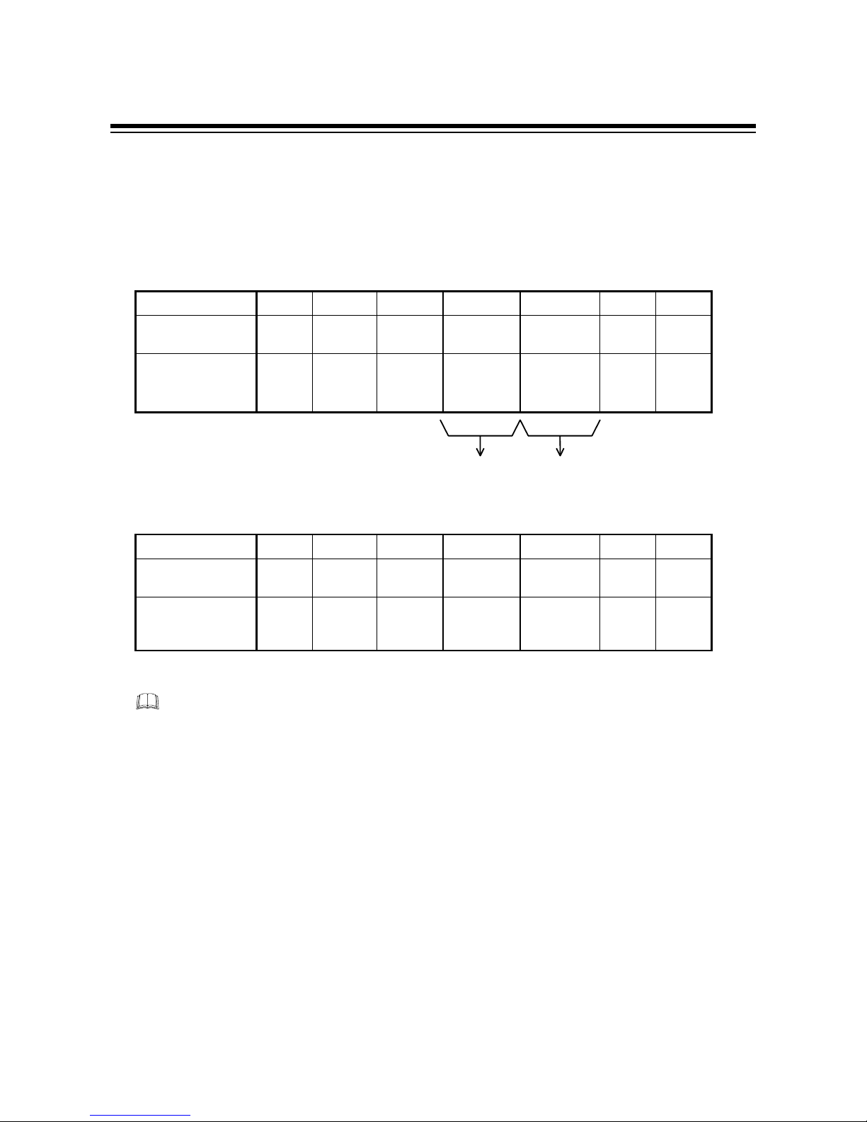
5.1.1 Communication data configuration
PLC o REX-F9000 (During data send from PLC)
cd efghi
Number of bytes
1122211
Number of BCD
digits
2244422
Details
STX
(02H)
ADR ID CMD DAT CR
(0DH)LF(0AH)
REX-F9000 o PLC (During data receive by PLC)
c d efgfg h i
Number of
bytes
1 1 22222 1 1
Number of
BCD digits
2 2 44444 2 2
Details
STX
(02H)
ADR ID CMD DAT CMD DAT CR
(0DH)LF(0AH)
c
STX
This is the transmission control character which indicates the start of the text (identifier and
data). Set to STX (02H) fixed.
d
ADR [Device address]
This data corresponds to the device address to select one REX-F9000 from among many
REX-F9000s to which the PLC is multi-drop-connected. This should be the same as the
device address set value in "
3.4 Device address setting
" (P.9).
......
......
.......
Page 44

5. LADDER COMMUNICATION
IM9000F02-E2
37
e
ID [Identifier]
These are numbers used for the PLC to identify data to be requested or set to the REXF9000.
These are numbers of four figures in the communication identifier list (P.44).
f
CMD [Command]
These are commands used for the PLC to identify the details of processing and the data sing
to be requested to the REX-F9000.
PLC o REX-F9000 (During data send fr om PLC)
Command
(CMD)
Details Identifier transfer order
(0000)
0001
Read request
Upper byte o Lower byte
0010 Write request, write data +(Positive)
0011 Write request, write data - (Negative)
0100 Read request (Byte inversion)
1000 Write request, write data +(Positive) Lower byte o Upper byte
1100 Write request, write data - (Negative)
Other Usage inhibited
REX-F9000 o PLC (During data receive by PLC)
Command
(CMD)
Details Identifier transfer order
0000 Read response, read data +(Positive) *1
0001 Read response, read data - (Negative) Upper byte o Lower byte
0010 Write response, write result data + (Positive)
0011 Write response, write result data - (Negative)
0100 Read response, read data - (Negative) Lower byte o Upper byte
1000 Read request, write result data + (Positive)
1100 Read request, write result data - (Negative)
Other Abnormal response
*
1
: Data transfer order is in accordance with the command from the PLC connected to the REX-F9000.
Page 45
5. LADDER COMMUNICATION
IM9000F02-E2
38
gggg
DAT [Data]
Details of
p
rocessin
g
by PLC
Communication direction Details of send/ receive data
Polling
PLC o REX-F9000 Number of read data (Maximum 30)
*For data read REX-F9000 o PLC Read data
*Data such as measured value (PV), etc.
Selecting
PLC o REX-F9000 Write data
*For data write REX-F9000 o PLC Data after write execution
hhhh, iiii
CR, LF [Delimit]
Control characters to indicate the end of a text. The REX-F9000 judges that the text ends if
it receives CR (0DH) and LF (0AH) in succession.
5.1.2 Data format
The data (DAT) format is expressed as internal data excluding the decimal point.
Example :
Data name Actual data Internal data
Manipulated output
value (MV)
-5.0 to +105.0 -0050 to +1050
Proportional band 0.001 to 50.000 0001 to 5000
PV bias -19.999 to +19.999 -1999 to +1999
Alarm 1 setting Process alarm : 0.000 to 50.000
Deviation alarm : -19.999 to +19.999
Process alarm : 0000 to 5000
Deviation alarm : -1999 to +1999
Page 46

5. LADDER COMMUNICATION
IM9000F02-E2
39
5.1.3 Data read
Reads identifiers requested from the PLC by the corresponding number of data items. A response
from REX-F9000 is returned as 4-digit BCD data excluding the sign data and decimal point.
Number of data which can be read at a time : 1 to 30.
PLC send data
Number of bytes
11 2 2 2 11
Number of BCD
digits
22 4 4 4 22
Details
STX
(02H)
Device
addres
s
(ADR)
Identifier
(ID)
0001 Read
data
CR
(0DH)LF(0AH)
Command Data (DAT)
(CMD)
REX-F9000 response under normal operation
Number of
bytes
1122222
Number of
BCD digits
2244444
Details
STX
(02H)
Device
address
(ADR)
Identifie
r
(ID)
0000 dddd1 0000 dddd2
Command Data (DAT) Data corresponding
(CMD) to identifier + 1
2211
4422
0000 ddddn CR LF
Data corresponding to
identifier + n - 1 (n : Number of read data)
If there is no identifier requested by the PLC, the REX-F9000 returns the "0000" data.
.....
.....
.....
.....
.....
.....
This numeric value changes
depending on the data sign
(+ or -). (0 or 1)
Page 47
5. LADDER COMMUNICATION
IM9000F02-E2
40
5.1.4 Data write
Writes the specified data in the specified identifier. Write data is specified by 4-digit BCD data
excluding the sign data and decimal point.
The number of data which can be written at a time is 1.
PLC send data
Number of bytes
11 2 2 2 11
Number of BCD
digits
22 4 4 4 22
Details
STX
(02H)
Device
address
(ADR)
Identifie
r
(ID)
0010
or
0011
dddd CR
(0DH)LF(0AH)
Command Setting data
(CMD)
REX-F9000 response
Number of bytes
11 2 2 2 11
Number of BCD
digits
22 4 4 4 22
Details
STX Device
address
(ADR)
Identifie
r
(ID)
0010
or
0011
dddd CR LF
The original data is returned by ignoring data write for either of the following cases.
z
The data range is exceeded, or
z
a write inhibit identifier is specified.
Page 48

5. LADDER COMMUNICATION
IM9000F02-E2
41
5.1.5 Reversal of read/write data bytes
There are two methods of sending word data : One is to send the data from the upper byte and the
other is to send the data from the lower byte.
The following two items can be inverted : Identifier (ID) and data (DAT).
Only the data (DAT) can also be inverted by setting.
Number of bytes
11 2 2 2 11
Number of BCD
digits
22 4 4 4 22
Details
STX
(02H)
Device
addres
s
(ADR)
Identifie
r
(ID)
Command
(CMD)
Data
(DAT)
CR
(0DH)LF(0AH)
These two items can be inverted
.
Inverting method
Reversal of Identifier (ID) and data (DAT)
The usual data transfer order is reversed by the command (CMD).
PLC o REX-F9000 (During data send fr om PLC)
Command
(CMD)
Details Identifier transfer order
(0000)
0001
Read request
Upper byte o Lower byte
0010 Write request, write data + (Positive)
0011 Write request, write data - (Negative)
0100 Read request (Byte inversion)
1000 Write request, write data + (Positive) Lower byte o Upper byte
1100 Write request, write data - (Negative)
Other Usage inhibited
Continued on the next page.
Page 49

5. LADDER COMMUNICATION
IM9000F02-E2
42
REX-F9000 o PLC (During data receive by PLC)
Command
(CMD)
Details Identifier transfer order
0000 Read response, Read data + (Positive) *1
0001 Read response, Read data - (Negative) Upper byte o Lower byte
0010 Write response, Write result data + (Positive)
0011 Write response, Write result data - (Negative)
0100 Read response, Read data - (Negative) Lower byte o Upper byte
1000 Write request, Write result data + (Positive)
1100 Write request, Write result data - (Negative)
Other Abnormal response
*1 : Data transfer order is in accordance with the command from the PLC connected to the REX-F9000.
Only data is inverted
Change can be made by specifying "0011" to the data number (ID) and setting data on "0 : High
orderoLow order " or "Other than 0 : Low orderoHigh order."
Number of bytes
11 2 2 2 11
Number of BCD
digits
22 4 4 4 22
Details
STX
(02H)
Device
addres
s
(ADR)
0011
Command
(CMD)
Set 0 or any
number other
than 0.
CR
(0DH)LF(0AH)
Identifier (ID) Data (DAT)
[Example]
The following procedure is executed for send/r eceive data of 1234h.
z
When sending data from the upper byte
When REX-F9000 sends data : Sends data in order of 12h and 34h.
When REX-F9000 receives data : When REX-F9000 receives data in order of 12h and 34h,
it
recognizes the data as 1234h.
z
When sending data from the lower byte
When REX-F9000 sends data : Sends data in order of 34h and 12h.
When REX-F9000 receives data : When REX-F9000 receives data in order of 12h and 34h,
it
recognizes the data as 3412h.
*This setting is held even if the power is turned on again.
Page 50

5. LADDER COMMUNICATION
IM9000F02-E2
44
5.1.6 REX-F9000 no response
The REX-F9000 issues no-response for any of the following cases.
z
The device address sent from the PLC does not match the device address of the
REX-F9000.
z
"CR" and "LF" can't be normally received.
z
When there is an error in the data type.
z
When a communication error occurs.
5.1.7 Example of text sent by PLC
Example of text
It is assumed that the address No. is 00 and that data notation is hexadecimal.
z
When reading measured value (PV)
PLC send
Measured value
(PV)
Identifier
Device
address
LFCR00230000010000STX
REX-F9000 response
Number of
read data
Identifier
CommandDevice
address
LFCR00010000010000STX
z
When writing set value (PV)
Set value
(SV)
Identifier
Device
address
LFCR00300010010500STX
Wr ite data
Command
Identifier
Device
address
REX-F9000 response
LFCR00300010010500STX
PLC send
Page 51

5. LADDER COMMUNICATION
IM9000F02-E2
45
5.2 Communication identifier
In RKC standard communication described above, each item is expressed by an identifier
combined with a number and a letter (M1, S1 ...) but in ladder communication, each item is
expressed only by a number.
(Attributes RO: Read only, R/W: Read/W rite)
Upper Lower
Measured value
(PV)
01 00
Within input range 1/100
qC
RO ----
Undefined
01 01
---------- ------ ---- ----
Manipulated
output
value (MV)
01 02
-0050 to +1050 1/10 % RO ----
Undefined
01 03
---------- ------ ---- ----
Alarm 1 output *1
Alarm 2 output
01 04
------ RO ----
Burnout
(Measured value)
Set value (SV)
01 05
Setting limiter (low limit
)
to
setting limiter (high limit)
1/100qCR/W 0000
Alarm 1 setting
01 06
Process alarm :
0.000 to 50.000 1/100qCR/W 0500
Alarm 2 setting
01 07
Deviation alarm :
-19.999 to +19.999
Undefined
01 08
01 09
Proportional band
01 10
0001 to 5000 qC R/W 3000
Undefined
01 11
---------- ------ ---- ----
Integral time
01 12
0001 to 3600 sec R/W 0240
Derivative time
01 13
0000 to 3600 sec R/W 0060
PID/AT transfer
01 14
0 : PID
1 : AT (Autotuning)
------ R/W 0000
AUTO/MANUAL
transfer
01 15
0 : AUTO
1 : MANUAL
------ R/W 0000
The amount of
manual output
01 16
Output limiter (low limit
)
to
output limiter (high limit)
1/10 % R/W
*2
----
#1 : Engineering unit
#2 : Attribute
Continued on the next page.
Identifier
Item
------ ---- ----
----------
Details of data #1 #2
Factory set
value
Page 52

5. LADDER COMMUNICATION
IM9000F02-E2
47
(Attributes RO: Read only, R/W: Read/W rite)
Upper Lower
PV bias
01 17
-1999 to +1999 1/100qCR/W 0000
Undefined
01
to
01
18
to
99
---------- ------ ---- ----
Control
RUN/STOP
00 00
0 : RUN 1 : STOP ------ R/W 0000
Reversing the
usual
data transfer order
*3
00 11
0: Upper byteoLower byte
Any number other than 0 :
Lower byteoUpper byte
------ R/W 0000
#1 : Engineering unit
#2 : Attribute
*1 : 0 0 0 0
"0" Fixed
When burnout occurred = 1
When the alarm 2 occurred = 1
When the alarm 1 occurred = 1
*2 : Data can be written only in manual mode.
*3 : Specified when only the data (DAT) block is inverted. If the inversion of transfer order is specified by the
command (CMD), this setting becomes invalid.
Identifier
Item Details of data #1 #2
Factory set
value
Page 53

5. LADDER COMMUNICATION
IM9000F02-E2
48
5.3 Example of sequence program
5.3.1 MELSEC Series (MITSUBISHI)
The ladder communication send/receive program using the MITSUBISHI MELSEC Series
(A2CCPU24) is described below.
Send data creation program (example)
M000
Send data
creation switch
D11H0002MOVP
D12H0100MOVP
D13H0001MOVP
D14H0001MOVP
D15H0A0DMOVP
Data setting
(Number of read data = 1)
Termination char acter
setting (CR, LF)
Command ( CMD) setting
Identifier setting
(Measured value)
STX setting
Address setting = 01
Send program (example)
Y1F0SET
K6D10H0K61TOP
Send request
resetting
Send request setting
Transfer t o send
buffer
Data length sett ingD10K5MOVP
Send completion
X1E0
Send
request
Send
completion
Send start
switch
Y1F0X1E0M001
Y1F0RST
Page 54

5. LADDER COMMUNICATION
IM9000F02-E2
47
Receive program (example)
ZD20MOVP
Receive data read
completion setting
Transfers receive data
from receive buffer
Stores character length
in index register
Acquisition of r eceive
character length
K1D20H80K61FROMP
Receive data
read request
X1E1
K0Z
Y1F1
D21H81K61FROMP
X1E0, X1E1, Y1F0, Y1F1 and K61 in the above program differ depending on the
programmable controller used to communication module address.
For details on setting the PLC, see the manual for "MITSUBISHI MELSEC Series."
Page 55

5. LADDER COMMUNICATION
IM9000F02-E2
48
5.3.2 C200HS (OMRON)
The communication send/receive program using the OMRON C200HS is described below.
The following types of OMRON C200HS with the built-in RS-232C post can perform nonprotocol communication.
z
C200HS-CPU21
z
C200HS-CPU23
z
C200HS-CPU31
z
C200HS-CPU33
Send data creation program (example)
Data setting (DAT)
Number of read data = 1
STX setting
Address setting = 01
Termination char acter
(CR, LF)
Command setti ng
(CMD)
Identifier setting
[Measured value (PV)]
MOV
#0D0A
D1004
MOV
#0001
D1003
MOV
#0001
D1002
MOV
#0100
D1001
MOV
#0201
D1000
Send data
creation switch
30000
Send program (example)
RSET
30001
TXD
D1000
#0000
#0010
30001 26405
Send start reset switch
Send data head register
Control data
Number of send data bytes
Send ready
flag
Send start
switch
Page 56

5. LADDER COMMUNICATION
IM9000F02-E2
49
Receive program (example)
Receive data head register
Control data
Number of stored data bytes
RXD
D1100
#0000
#0256
26406
Receive completion
flag
For details on setting the PLC, see the manual for "OMRON C200HS."
Page 57

50
IM9000F02-E2
6. TROUBLESHOOTING
The causes of and measures to be used for faulty controller status during communication are
described in the following. For trouble other than the below, contact us or your nearest RKC agent
after confirming Model No. and specifications.
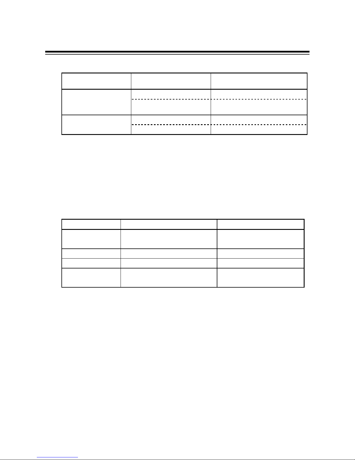
RKC standard communication
Details Cause Measures
Trouble with and imperfect contact of
communication cable and connector
Check communication cables and connectors.
Device address designation differs Make reassignment after checking the device
address by referring to
"
3.4 Device address setting
" (P.9).
Incorrect communication speed Set the communication speed suitable for the
host computer by referring to
"
3.5 Communication speed setting
"
(P.11).
Incorrect data configuration setting Make reassignment after checking the data
configuration by referring to
"
3.6 Data configuration setting"
(P.13).
No response
Transmission line is not set to the receive
state after data send
Check a program on the host computer side.
Incorrect identifier Make re-setting after checking the identifier
by
EOT return
The identifier of a function not added to
the REX-F9000 is specified
referring to
"
Communication identifier list
" (P.31).
BCC error Check BCC of the transmission data.
Data exceeds the setting range Check a data range.
NAK return
The identifier of a function not added to
the REX-F9000 is specified
Make re-setting after checking the identifier
by
referring to
"
Communication identifier list
" (P.31).
Page 58

6. TROUBLESHOOTING
IM9000F02-E2
51
Ladder communication
Details Cause Measures
Trouble wit and imperfect contact
communication cable and connector
Check communication cables and
connectors.
Device address designation differs Make reassignment after checking
the
device address by referring to
"
3.4 Device address setting
"
(P.9).
Incorrect communication speed
Set the communication speed suitable
for the PLC by referring to
"
3.5 Communication speed
setting
" (P.11).
No response Incorrect data configuration setting
Make reassignment after checking
the
data configuration by referring to
"
3.6 Data configuration setting"
(P.13).
Transmission line is not set to the
receive state after data send
Check the program on the PLC side.
The specified identifier is not defined. Check the identifier.
The number of read data exceeds the
specified number.
Check the number of data.
No command length is correct
*Command length must be 10 bytes including
CR and LF.
Check the PLC side program.
No settings are written Write data is out of the range Check a setting range.
An unsettable identifier (measured
value,
etc.) was specified.
Check whether they are identifiers
corresponding to settable items.
All return characters
other than STX, device
address, identifier, CR
and LF are set to F.
Characters other than BCD codes (0 to
9) were used for communication data
(excluding STX, CR and LF)
Make conversion to BCD coded
characters.
Page 59

52
IM9000F02-E2
7. ASCII 7-BIT CODE TABLE
b700001111
b600110011
b501010101
b5 to b7b4b3b2b1 01234567
00000NULDLE SP 0 @ P ‘ p
00011SOHDC1 ! 1 A Q a q
00102STXDC2 ” 2 B R b r
00113ETXDC3 # 3 C S c s
01004EOTDC4 $ 4 D T d t
01015ENQNAK % 5 E U e u
01106ACKSYM & 6 F V f v
01117BELETB ’ 7 G W g w
10008 BS CAN ( 8 H X h x
10019 HT EM ) 9 I Y i y
1010A LF SUB * : J Z j z
1011B VT ESC + ; K [ k {
1100C FF FS , < L ¥ l |
1101DCR GS - = M ] m }
1110E SO RS . > N ^ n ˜
1111F SI US / ? O _ o DEL
Page 60

IM9000F02-E2 JUL.1999
RKC INSTRUMENT INC.
HEADQUARTERS: 16-6, KUGAHARA 5-CHOME, OHTA-KU TOKYO 146-8515 JAPAN
PHONE: 03-3751-9799 (+81 3 3751 9799)
E-mail: info@rkcinst.co.jp
FAX: 03-3751-8585 (+81 3 3751 8585)
 Loading...