

Page 1
A
A
e
e
e
y
e
r
(1)
(1)
(
*
(
)
*
X
35
4
6
)
A
A
)
17
23
1
26 25
26 25 27
25
26 25
26 25
27
26 25
27
20 19
Resin Pressure Digital Controller
HA430/HA930
Thank you for purchasing this RKC product. In order to achieve maximum performance and ensure
proper operation of your ne w instrument, carefully r ead all the instructions in this manual. Pleas e
place the manual in a convenient location for easy reference.
For detailed handling procedures an d key operations, refer to separate
HA430/HA930 Operatio n Man ual (IMR01 N12-E ).
The manual can be downloaded from the official RKC website:
http://www.rkcinst.com/english/manual_load.htm.
To prevent injury to persons, damage to instrument and equipment, a
suitable external protection device shall be requir ed.
All wiring must be completed before power is turned on to prevent electric
shock, fire or damage to instrument and equipment.
This instrument must be used in accordance with the specifications to
prevent fire or damage to instrument and equipment.
This instrument is not intended for use in locations subject to flammable or
explosive gases.
Do not touch high-voltag e connections such as power supply terminals,
etc. to avoid electric shock.
RKC is not responsible if this instrument is repaired, modified or
disassembled by other than factor y-approved personnel. Malfunction can
occur and warranty is void under these conditions.
!
WARNING
Instruction
Manual
IMR01N11-E7
This product is intended fo r use with in dustrial machines , test and measurin g equipmen t. (It is no t
designed for use with medica l equipm ent and nuc lear ener gy.)
T his is a Class A instrument. In a domestic enviro nment, this instrument may cause radio
interference, in which case the user may be required to take additional measures.
This instrument is protected from electric shock by reinforced insulation. Provide reinforced
insulation between the wire for the input signal and the wires for instrument power supply, source
of power and loads.
Be sure to provide an appropriate surge control circuit respectively for the following:
CAUTION
If input/output or signal lines within the building are longer than 30 meters.
If input/output or signal lines leave the building, regardless the length.
This instrument is designed for installation in an enclosed instrumentation panel. All high-voltage
connections such as power supply terminals must be enclosed in the instrumentation panel to
avoid electric shock by operating personnel.
All precautions described in this manual should be taken to avoid damage to the instrument or
equipment.
All wiring must be in accordance with local codes and regulations.
All wiring must be completed before power is turned on to prevent electric shock, instrument failure,
or incorrect action. The power must be turned off before repairing work for input break and output
failure including replacement of sensor, contactor or SSR, and all wiring must be completed before
power is turned on again.
To prevent instrument damage as a result of failure, protect the power li ne and the inpu t/output
lines from high currents with a suitable overcurrent protection device with adequate breaking capacity
such as fuse, circuit brea ker, etc .
Prevent metal fragments or lead wire scraps fro m fall ing in side i nstr umen t case to a void e lectric
shock, fire or malfunctio n.
Tighten each terminal screw to the specif ied t orqu e found in th e manu al to avoi d ele ctric s hock,
fire or malfunction.
For proper operation of this instrument, provide adequate ventilation for heat dispensation.
Do not connect wires to unused terminals as this will interfere with proper operat ion of the
instrument.
Turn off the power supply before cleaning the instrument.
Do not use a volatile solvent such as paint thinner to clean the instrument. Deformation or
discoloration will occur. Use a soft, dry cloth to remove stains from the instrument.
To avoid damage to instrument display, do not rub with an abrasive material or push front panel
with a hard object.
Do not connect modular connectors to telephone line.
When high alarm with hold action/re-hold action is used for Event functio n, alarm does not turn
on while hold action is in operation. Take measures to prevent overheating which may occur if
the control device fails.
NOTICE
This manual assumes that the reader has a fundamental knowledge of the principles of
electricity, process contr ol, c omput er te chnol ogy a nd co mmunic ation s.
The figures, diagrams and numeric values used in this manual are only for purpose of illustration.
RKC is not responsible for any damage or injury that is caused as a result of using this
instrument, instrument failure or indirect damage.
RKC is not responsible for any damage and/or injury resulting from the use of instruments made
by imitating this instru ment.
Periodic maintenance is required for safe and proper operation of this instrument. Some
components have a li mited serv ice l ife, or char acter istic s tha t cha nge ov er t ime.
Every effort has been made to ensure accuracy of all information contained herein. RKC makes
no warranty expressed or implied, with respect to the accuracy of the information. The
information in this manual is subject to change without prior notice.
No portion of this document m ay be reprinted, modified, copied, transmitted, digi tized, stored,
processed or retrieved thro ugh any mec hanical, ele ctronic, opti cal or other means with out prior
written approval from RKC.
Mounting brackets: 2 [HA430], 4 [HA930]
Instruction Manual: 1 (IMR01N11-E7)
Product Check
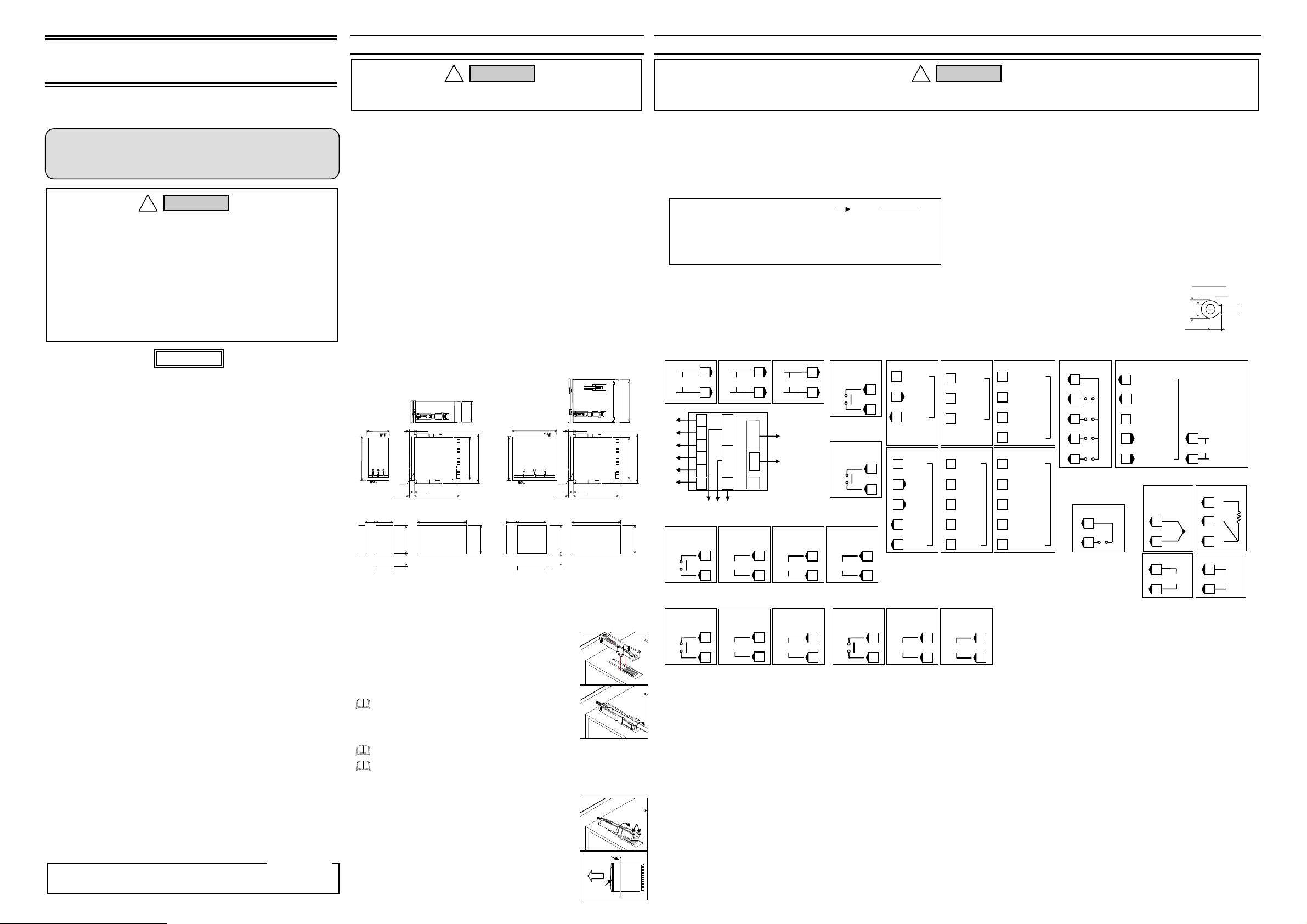
1. MOUNTING
To prevent electric shock or i nstrument failure, always t urn off the
power before mounting or removing the instrument.
Mounting Cautions
(1) This instrument is intended to be used under the following environmental conditions.
(IEC61010-1) [OVERVOLTAGE CATEGORY II, POLLUTION DEGREE 2]
(2) Use this instrument within the following environment conditions:
Allowable ambient temperature: 10 to 50 C (14 to 122 F)
Allowable ambient humidity: 5 to 95 %RH
Install ation e nviro nment cond ition s: Indoor us e, Al titud e up t o 200 0 m
(3) Avoid the following conditions when selecting the mounting location:
Rapid changes in ambient temperature
which may cause condensation.
Corrosive or inflam mable gas es.
Direct vib ration o r shock to th e mainfra me.
Water, oil, chemicals, vapor or steam
splashes.
(4) Mount this instrument in the panel considering the following conditions:
Provide adequate ventilation space so that heat does not build up.
Do not mount this instrument directly above equipment that generates large amount of heat
(heaters, transformers, semi-conductor functional devices, large-wattage resistors.)
If the ambient temperature rises above 50 C (122 F), cool this instrument with a force d air fan,
cooler, etc. Cooled air should not blow direct ly on this instrumen t.
In order to improve safety and the immunity t o withsta nd noise , mount thi s instru ment as far
away as possible from high voltage equipment, power lines, and rotating machinery.
High voltage equipment: Do not mount within the same panel.
Power lines: Separate at least 200 mm.
Rotating machinery: Separate as far as possible.
For correct functioning mount this instrument in a horizontal position.
(5) In case this instrument is connected to a supply by means of a permanent connection, a switch or
circuit-breaker shall be included in the installation. This shall be in close proximity to the equipment
and within easy reach of the operator. It shall be marked as the disconnecting device for the
equipment.
Dimensions
HA430
(Unit: mm)
48
11.1
96
25
*1
10.1
0.6
45
0
0.8
100
Close mounting
L
0
92
L = 48×n-3
30
n: Number of units
0.6
0
Individual mounting
*1 Rubber
*2 If the HA430s or HA930s have water proof/dustproof, protection will be com promised and not meet IP65 by clos
mounting.
*3 When controllers are closely mounted, ambient temperature must not exceed 50 °C (122°F).
For mounting of the HA430 or HA930, panel thickness must be between 1 to 10 mm.
When mounting multiple HA430s or HA930s close together, the panel strength should be checked t o ensure prope
support.
Mounting Procedures
1. Prepare the panel cutout as specified in Dimensions.
2. Insert the instrument thr ough the panel cu tout.
3. Insert the mounting brac ket into the mounti ng groove of the inst rument.
Do not push the mounting bracket forward. (Fig. 1)
4. Secure the bracket to the instrument by tightening the screw.
Take care to refrain from moving the bracket forward.
Only turn about one full revolution after the screw touches the panel.
5.
If the screw has been rotated too tight , the scr ew may turn
idle. In such a case, loosen the screw once and tighten it
again until the instrumen t is firmly fixed.
6. The other mounting bracket should be installed in the same way
described in 3. to 5.
When the instrument is moun ted, always secure with two mounting brac kets so that upper
and lower mounting brackets are posit ioned di agonally .
The waterproof/dustproof ( optional) on the front of the in strument conforms to IP65 whe n
mounted on the panel. For effective waterproof/dustproof, the gasket must be securely
placed between instrument and pa nel wi thou t a n y ga p. I f g as ket is d am ag ed , pl ea se co nt ac t
RKC sales office or the agent.
Removal Procedures
1. Turn the pow er OFF.
2. Remove the wiring.
3. Loosen the screw of the mounting bracket.
4. Hold the mounting bra cket by th e edge () and tilt it () to remove from
the case. (Fig. 3)
5. The other mounting bracket should be removed in the same way as
described in 3. and 4.
6. Pull out the instrument from the mounting cutout while holding the front
panel frame of this instrument. (Fig. 4)
WARNING
!
(Absolute humidity: MAX. W. C 29 g/m
Excessive dus t, salt o r iron part icles.
Excessive induction noise, static electricity,
magnetic fields or noise.
Direct air flow from an ai r condit ioner.
Exposure to di rect sun light.
Excessive heat accumulation.
HA930
(Unit: mm)
44.8
91.8
2, *3
110.8
0.8
0
92
2 to 6)
96
96
Individual mounting
0.8
25
92
0
(Fig. 2)
3
dry air at 101.3 kPa)
11.1
*1
10.1
Close mounting
0.8
0
92
L = 96×n-4
30
n: Number of units
Front panel
frame
100
L
Panel
Pull out
0.8
0
2, *3
91.8
91.8
0.8
0
92
2to 6
Fig.1
Fig.2
Fig. 3
Fig. 4
110.8
2. WIRING
To prevent electric shock or instr ument failure, do not turn on the po wer until all wiring is completed. Mak e sure that the wiring is correct
before applying power to th e instrume nt.
Wiring Cautions
For thermocouple input, use the appropriate compensation wire.
For RTD input, use low resistance lead wire with no difference in resistance between the three
lead wires.
Use a special shielded cable for connection with the pressure sensor.
When using our CZ-100P or CZ-200P:
The rated output (mV/V) of pre ssure se nsor is wh en the cab le is at a le ngth of 5 m.
If the cable is extended, correct the rated output using the following equation.
Set the correction value thus calculated to “Gain setting.”
For the Gain setting screen, refer to HA430/HA930 Operation Manual (IMR01N12-E).
Correction equation:
e1: Rated output in standard-cable length 5 m (mV/V is described on the nameplate of the sensor)
e2: Rated output after extension
K: Correction factor* 1.96 10
1.40 10
* When using 0.5 mm
L: Extended cable length (m)
To avoid noise induction, keep input signal wire away from instrument power line, load lines
and power lines of other electric equipment.
Signal connected to Voltage input and Current input shall be low voltage defined as “SELV”
circuit per IEC 60950-1.
If there is electrical noise in the vicinity of the instrument that could affect operation, use
a noise filter.
e1 e2 (1 K L)
4
/m [Non-explosionproof specification type],
4
/m [Explosionproof specification type]
2
4-core shielded cable (standard-cable) or equal.
e2
e1
1 K L
Terminal Configuration (All the terminal configuration of HA430 and HA930 is the same.)
OUT5
OUT4
Sensor
(Optional
OUT1
4
(7) Communication 2 (Optional)
RS-232C
SG
3
26
SD
4
27
RD
RS-422A
5
6
SG
T (A)
27
T (B)
R (A)
28
29
R (B)
7
8
Voltage pulse/
Voltage/Current
OUT1
11
12
(1) Power supply
(1)
(2)
(3)
(4)
(5)
(6)
(4) Output 3
(5) Output 2 1
C
L
100-240 V
N
Relay contact
OUT3
NO
Relay contact
OUT2
NO
1
2
1
2
3
4
5
6
7
8
9
10
11
12
(8)(7) (9)
3, 4
7
8
9
10
C
L
24 V
N
25
26
27
28
29
30
31
32
33
34
35
3
Terminal numbers 13, 22: Unused
Voltage pulse/
Voltage/Current
OUT3
DC
1
24 V
2
13
14
15
16
(10)
17
18
19
20
(11)
21
22
23
2
Triac
OUT3
7
8
Voltage pulse/
Voltage/Current
OUT2
9
Triac
OUT2
10
1
2
7
8
9
10
(2) Output 5
Relay contact
NO
(3) Output 4 4
Relay contact
NO
power supply
24 V DC
(6) Output 1 1
Relay contact
NO
Specifications
Power supply voltage:
90 to 264 V AC [Power supply voltage range], 50/60 Hz (Rating: 100 to 240 V AC)
21.6 to 26.4 V AC [Power supply voltage range], 50/60 Hz (Rating: 24 V AC)
21.6 to 26.4 V DC [Power supply voltage range] (Rating: 24 V DC)
Power consumption:
HA430: 16.5 VA max. (at 100 V AC) 22.5 VA max. (at 240 V AC)
HA930: 17.5 VA max. (at 100 V AC) 24.0 VA max. (at 240 V AC)
Input 1: Pressure sensor input
Input 2: TC input, RTD input, Voltage input, Current input
Optional input: Remote input (Not isolation type), Event input
Power supply for strain gauge type of pressure sensor:
Sensor power supply output (Optional): OUT3 is used
15.0 VA max. (at 24 V AC) 430 mA max. (at 24 V DC)
16.0 VA max. (at 24 V AC) 470 mA max. (at 24 V DC)
Relevant sensor: Strain gauge type pressure sensor
Rated voltage (EXC): 8 V DC 3 %
Temperature drift: 80 ppm/C
Rated current 30 mA max.
Rated voltage: 24 V DC 5 %
Rated current: 24 mA max.
WARNING
!
- Shorten the distance between the twisted powe r supply wire pit ches to achie ve the most effectiv
noise reduction.
- Always install the noise filter on a grounded panel. Minimize the wiring distance between the noise
filter output and the instrument power supply terminals to achieve the most effective nois
reduction.
- Do not connect fuses or switches to the noise filter output wiring as this will reduce th
effectiveness of the noise filter.
Allow approximately 5 seconds for contact output when the i nstrument is turned on. Use a dela
relay when the output line is used for an external interlock circuit.
Power supply wiring must be twisted and have a low voltage drop.
This instrument with 24 V power supply is not provided with an overcurrent protection device.
For safety install an overcu rrent pr otectio n device (such as fu se) wit h adequate breakin g capaci ty
close to the instrument.
- Fuse type: Time-lag fuse (Approved fuse according CSA C22.2 No.248.14 or UL248-14)
- Fuse rating: Rated current: 1.0 A
For an instrument with 24 V power supply input, supply power from “SELV” circuit defined as IEC
60950-1.
A suitable power supply should be considered in the end-use equipment. The power supply must be
in compliance with a limited-energy circuits (maximum available current of 8 A).
Use the solderless terminal appropriate to the screw size.
- Screw size: M3×6 (With 5.8×8 square washer)
- Recommended tightening torque: 0.4 N・m (4 kgf・cm)
- Specified solderless terminals: With isolation
- Applicable wire: Solid/twisted wire of 0.25 to 1.65 mm
Make sure that during fi eld wiring parts of cond uctors can not
come into contact with adjacent conductive par ts.
5
(8) Input
RS-485
SG
T/R (A)
27
T/R (B)
DeviceNet
V
CAN-H
Drain
28
CAN-L
29
V
PROFIBUS
VP
RxD/TxD-P
RxD/TxD-N
28
DGND
CC-Link
DA
DB
DG
28
SLD
29
FG
Contact
30
DI1
31
DI2
32
DI3
33
DI4
34
(Optional
(9) Input 5
Contact
36
(Optional)
DI5
2
(10) Pressure sensor input (Input 1)
Strain gauge input
CAL
14
CAL
15
SHD (E)
16
EXC (A)
EXC (C)
18
(11) Input (Input 2)
TC
20
TC2
21
Voltage/Current
20
IN2
21
OUT1 and OUT2 are not isolated from each other except for relay ortriac output.
Triac
OUT1
11
12
Output 1 to Output 3:
Relay contact output: 250 V AC, 3 A (Resistive load), 1a contact
Electrical life: 300,000 times or more (Rated load)
Voltage pulse output: 0/12 V DC (Allowable load resistance 600 or more)
Current output: 0 to 20 mA DC, 4 to 20 mA DC
(Allowable load resistance 600 or less)
Voltage output: 0 to 5 V DC, 1 to 5 V DC, 0 to 10 V DC
(Allowable load resistance 1 k or more)
Triac output: Allowable load current: 0.4 A Minimum load current: 30 mA
Load voltage: 75 to 250 V AC
Output 4 and Output 5:
Relay contact output: 250 V AC, 1 A (Resistive load), 1a contact
Electrical life: 300,000 times or more (Rated load)
Control method: Brilliant PID control
(Direct action or Reverse action is available)
llowable ambient temperature: 10 to 50 C (14 to 122 F)
llowable ambient humidity: 5 to 95 %RH
Absolute humidity: MAX. W.C 29 g/m
Operating environment: There should be neither corrosive gases nor much dust.
Weight: HA430: Approx. 360 g HA930: Approx. 460 g
2
Remote input is not isola ted from pressure sensor in put (strai n gauge input).
3
OUT3 can be used as a sensor power supply (optional) for the pressure sensor
with amplifier or 2-wire pressure transmitter.
4
11
When OUT3 is used for a sensor power supply (optional), OUT4 and OUT5 are
not available.
5
When the CC-Link communication (o ptional) i s specifie d, these term inals are
12
not available.
3
5.5 MA
4 mm
24
dry air at 101.3 kPa
3.2 MIN
SIG (D)
SIG
2
RTD
A
RTD2
B
21
B
Remote
19
RS
20
(B)
Page 2
r
A
A
t
t
r
p
(
)
r
A
A
A
AREA
A
A
T
A
T
k
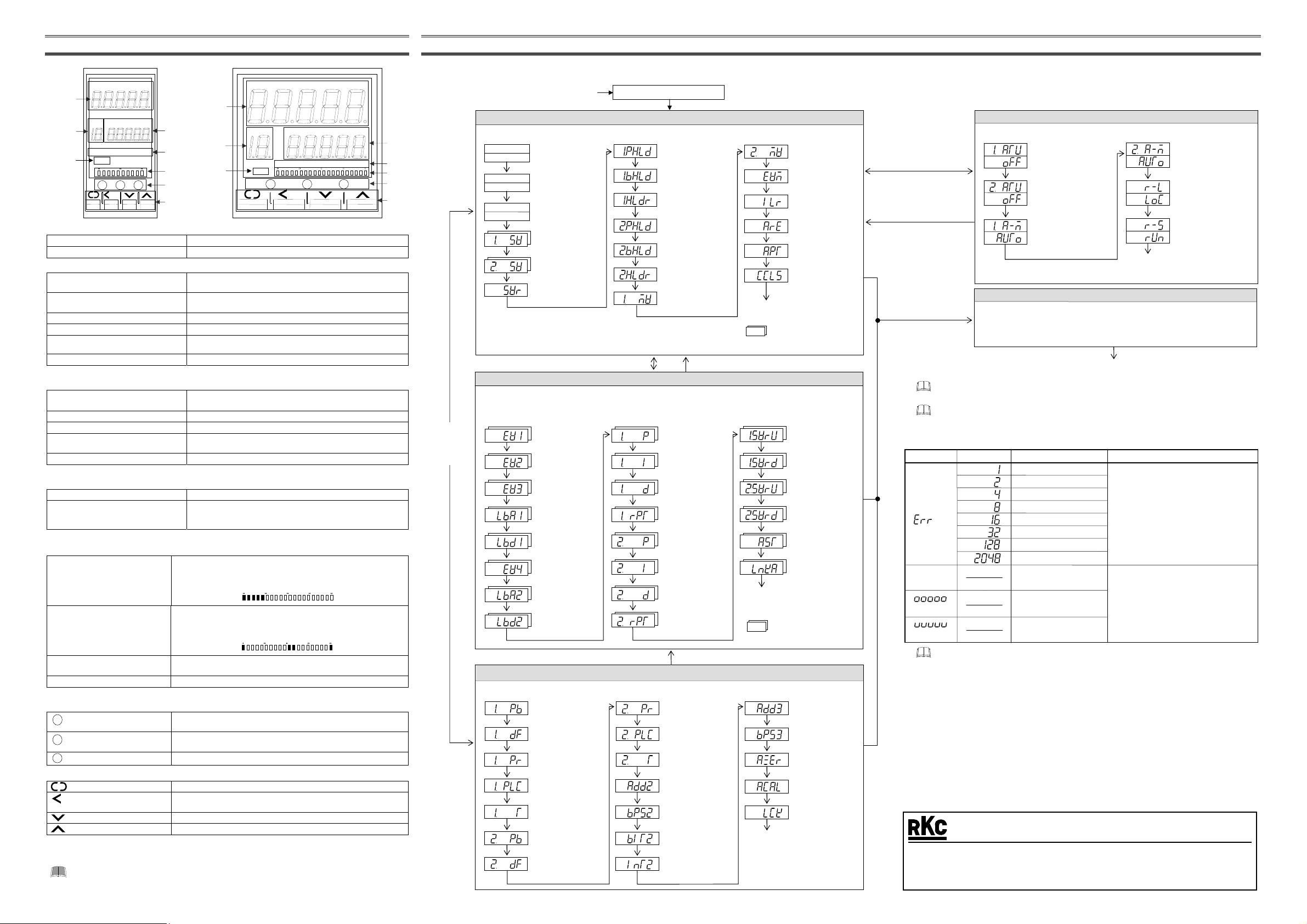
3. PARTS DESCRIPTION
(2)
(1)
(8)
(1) Area display
Area (AREA) lamp [Green] Lights when memory area number is displ ayed.
Memory area display Displays memory area numbe r (1 to 16) .
(2) Upper display
Measured value 1 (PV1) lamp [Green]
Measured value 2 (PV2) lamp * [Green]
Manual (MAN) mode lamp [Green] Lights when operated in manual mode.
Remote (REM) mode lamp [Green] Lights when remote setting function is activated.
Autotuning (AT) lamp [Green]
Measured value (PV1/PV2) display Displays PV1, PV2 or various parameter symbols.
* This lamp is activated only with 2-input controller .
(3) Lower display
Measured value 2 (PV2) lamp * [Green]
Set value (SV) lamp [Green] Lights when set value (SV) is displayed on the SV display unit.
Manual (MAN) mode lamp * [Green] Lights when operated in manual mode.
Autotuning (AT) lamp * [Green]
Set value (SV) display Displays SV, PV2 or various parameter set values.
* This lamp is activated only with 2-input controller .
(4) Output/Alarm lamp
Output (OUT1 to OUT5) lamp [Green] Lights when the output corresponding to each lamp is ON.
Alarm (ALM) lamp [Red]
(5) Bar graph display *
One of the displays shown in the table below can be selected for the bar-graph.
Manipulated output value (MV)
display
Deviation display
Measured value display
Set value display Displays the set value (SV). Scaling is available within the input range.
* The number of dots: 10 dots (HA430), 20 dots (HA930)
(6) Direct key
Auto/Manual transfer key Switching the Auto/Manual control mode between Auto (PI control)
A/M
Remote/Local transfer key Swit ching the Remote/Local control mode between Remote control
R/L
R/S
RUN/STOP transfer key Switching the RUN/STOP mode between RUN and STOP.
(7) Operation key
SE
MODE
(8) Infrared port
Used when sending and receiving data between this controller and the PDA installed with the RKCIR software.
To avoid damage to the instrument, never use a sharp object to press keys.
HA430
PV1 PV2 MAN REM AT
PV1
HA930
PV2 MAN
REM
(2)
PV2 MAN REM AT SV
OUT1 OUT2 OUT3 OUT4 OUT5 ALM
/M R/L R/S
SET
MODE
(3)
(4)
(5)
(1)
(8)
(6)
(7)
Lights when measured value 1 (PV1) is displayed on the PV1/PV2
display unit.
Lights when measured value 2 (PV2) is displayed on the PV1/PV2
display unit.
Flashes when autotuning is activ ated.
(After autotuning is completed: AT lamp will go out)
AREA PV2 MAN REM AT SV
OUT1 OUT2 OUT3 OUT4 OUT5 ALM
/M R/L R/S
SE
MODE
Lights when measured value 2 (PV2) is displayed on the SV
display unit.
Flashes when autotuning is activ ated.
(After autotuning is completed: AT lamp will go out)
Lights when alarm (Event function)
The type of alarm which is on can be checked on the event
monitor display.
Displays the manipulated output value (MV). When manipulated output
value (MV) is at 0 % or less, the left-e nd dot of the bar-gra ph flashes.
When MV exceeds 100 %, the right-end dot flashes.
[Example]
0 50
is turned on.
100
Displays the deviation betwee n the measured value (P V) and the set
value (SV). When the Deviation display is se lected, the dots at both
ends of bar-graph light.
[Example]
0
Displays the measured value (PV). Sca lin g is a vail able wit hi n t he inp ut
range.
mode and Manual mode.
and Local control.
Set (SET) key Used for parameter calling up and set value registration.
Shift key
Shift digits when settings are changed. Used to selection operation
between modes.
Down key Decrease numerals.
Up key Increase numeral s.
T
(3)
(4)
(5)
(6)
(7)
4. OPERATION FLOW OF EACH MODE
In order to make this instrument operable aft er being mount ed on equ ipment and then wired, it needs to be set with operat ing condit ions such as the set va lue (SV), input/ output function, contro l function, etc. specif ic to each customer. In addit ion, the following
operational flowchart illustrates key operation in each mode or each setting item. When actually setting these operating conditions specific to the customer, refer to the HA430/HA930 Operation Manual (IMR01N12-E).
Press the
shift key while
pressing the
SET key
Power ON
In this mode, it is possible to set SV which is the desired value for control and also to monitor PV, SV, MV, etc.
PV1 value
SV1 value
PV2 value
SV2 value
PV1 value
PV2 value
PV1/SV1 monitor
SET key
PV2/SV2 monitor
SET key
PV1/PV2 monitor
SET key
Input 1_SV setting
SET key
Input 2_SV setting
SET key
Remote input value
monitor
SET key
1
Remote input: Displays the remote set value.
2
Manual operation: Manipulated output value (MV1) o f Input 1 can be s et.
In the monitoring statu s, MV scaling valu e is displayed on the SV display.
3
Manual operation: Manipulated output value (MV2) o f Input 2 can be s et.
Press and hold the SET key for 2 seconds
In this mode, it is possible to set parameters relating to control such as PID constants, event set values, etc. Up to
16 individual sets of SVs and parameters in Parameter setting mode can be stored and used in Multi-memory area
function.
Event 1 set value
SET key
Event 2 set value
SET key
Event 3 set value
SET key
LBA1 time
SET key
LBA1 deadband
SET key
Event 4 set value
SET key
LBA2 time
SET key
LBA2 deadband
SET key
In this mode, it is possible to set setting items not corresponding to the memory area, setting lock levels, etc.
Input 1_PV bias
SET key
Input 1_digital filter
SET key
Input 1_PV ratio
SET key
Input 1_PV low input
cut-off
SET key
Input 1_proportional
cycle time
SET key
Input 2_PV bias
SET key
Input 2_digital filter
SET key
Input type/Input range Display
SV Setting & Monitor Mode
1, 2
SET key
3
SET key
SET key
SET key
SET key
SET key
SET key
Parameter Setting Mode
SET key
SET key
SET key
SET key
SET key
SET key
SET key
SET key
Setup Setting Mode
SET key
SET key
SET key
SET key
SET key
SET key
SET key
PV1 peak hold
value monitor
PV1 bottom hold
value monitor
PV1 hold reset
PV2 peak hold
value monitor
PV2 bottom hold
value monitor
PV2 hold reset
Input 1_MV monitor
Return to PV1/S V1 mon ito r
Press the shift key while pressing the SET key
Input 1_proportional
band for PI/PID
control
Input 1_integral time
for PI/PID con tr ol
Input 1_derivative
time for PID control
Input 1_control
response parameter
Input 2_proportional
band for PI/PID
control
Input 2_integral time
for PI/PID con tr ol
Input 2_derivative
time for PID control
Input 2_control
response parameter
Press and hold the SET key for 2 seconds
Return to first parameter setting
item of Parameter settin g mode
Input 2_PV ratio
Input 2_PV low input
cut-off
Input 2_proportional
cycle time
Device address
(Slave address)
Communication
speed
Data bit configuration
Return to first parameter setting
item of Setup setting mode
Interval time
Input 2_MV monitor
SET key
Event monitor
SET key
Interlock release
SET key
Memory area
selection
SET key
Memory area soak
time monitor
SET key
CC-Lin
communication status
SET key
: Parameters related to
Multi-memory area function
_
setting change
Input 1
rate limiter (up)
SET key
Input 1
_
setting change
rate limiter (down)
SET key
SET key
SET key
_
setting change
Input 2
rate limiter (up)
_
setting change
Input 2
rate limiter (down)
rea soak time
SET key
Link area number
SET key
: Parameters related to
Multi-memory area function
Infrared communication
address
SET key
Infrared communication
speed
SET key
uto-zero
(Pressure sensor)
SET key
uto calibration
(Pressure sensor)
SET key
Set lock level
SET key
Operation Mode
In this mode, it is possible to selects the operation modes of the instrument.
Press and hold the shift key for
1 second
Press the shift key while
pressing the SET key
Input 1_PID/AT transfer *
SET key or Shift key
Input 2_PID/AT transfer *
SET key or Shift key
Input 1_Auto/Manual
transfer
SET key or Shift key
Input 2_Auto/Manual
transfer
SET key or Shift key
Remote/Local transfer
SET key or Shift key
RUN/STOP transfer
SET key or Shift key
Return to Input 1_PID/AT transfer
* Factory shipment: No transfer from PID to AT can be made ( PID only )
Press the shift key while
pressing the SET key fo
2 seconds
In this mode, it is possible to set operating conditions suc h as the Input/Output
Engineering Mode
function, control function, etc. specific to each customer. For details, refer to
HA430/HA930 Operation Manual (IMR01N12-E).
This instrument returns to the PV1/SV1 monitor screen if no ke y operation is performed fo
more than 1 minute.
Parameters which are not related to existing functions on the controller are not displayed.
(Except Engineering mode)
Return to PV1/SV1 monitor of SV setting & Monitor mode
Press the shift key while pressing the SET key
Display of self-diagnostic error and overscale/undersc ale
Upper display
Measured
value (PV)
[Flashing]
Lower display
[Flashing]
[Flashing]
If two or more errors occur simultaneously, the error code numbers are totaled and displayed
as one number.
Description Solution
djusted data error
EEPROM error
/D conversion error
RAM check error
Turn off the power at once. If error occu rs
after the power is turned on a gain, please
contact RKC sales office or the agent.
Hardware configuration error
Software configuration error
Watchdog timer error
Program busy
Displays when the measured value (PV)
Input error
Over-scale
Underscale
exceeds the input error determination poin
(high or low limit) or display range limi
(19999 to 99999). Check the sensor o
input lead.
* Input error determination point (high limit):
Input scale high (5 of input span)
Input error determination point (low limit):
ut scale low
In
5 of input span
Operation of various functions
For the operation of various functions, refer to the HA430/HA930 Operation Manual (IMR01N12-E).
For the communication function, refer to the following manuals.
HA430/HA930 Communication Instruction Manual [RKC communication/Modbus] (IMR01N13-E)
HA430/HA930 PROFIBUS Communication Instruction Manual (IMR01N14-E)
HA430/HA930 DeviceNet Communication Instruction Manual (IMR01N15-E)
HA430/HA930 CC-Link Communication Instruction Manual (IMR01N21- E)
For an instrument with Z-1145 specification, refer to the following instruction manuals.
HA430/HA930 Z-1145 Specification (IMR01N26-E)
The above manuals can be downloaded from the official RKC website:
http://www.rkcinst.com/english/manual_load.htm.
Modbus is a registered trademark of Schneider Electric.
DeviceNet is a registered trademark of Open DeviceNet Vender Association, Inc.
CC-Link is a registered trademark of Mitsubishi Electric Co. Ltd.
RKC INSTRUMENT INC.
®
The first edition: AUG. 2003 [IMQ00]
The seventh edition: FEB. 2012 [IMQ00]
HEADQUARTERS: 16-6, KUGAHARA 5-CHOME, OHTA-KU TOKYO 146-8515 JAPAN
PHONE: 03-3751-9799 (+81 3 3751 9799)
E-mail: info@rkcinst.co.jp
FAX: 03-3751-8585 (+81 3 3751 8585)
MAY 2013
 Loading...