


RJ MOBILITY LTD.
METEOR & MINI-METEOR
TECHNICAL MANUAL
PROVIDING
ACTIVE USER
INDEPENDENCE
This Technical Manual will ensure that
the wheelchair is maintained to the
required standard and is for use by
trained personnel only.

This Technical Manual contains important information regarding maintenance of the Meteor
and Mini-Meteor wheelchairs thus ensuring their safe operation. Please make sure that y ou
understand all instructions thoroughly.
It is recommended that maintenance is undertaken at six monthly intervals for a wheelchair
that is in constant daily use.
The safety of the wheelchair user is paramount. If there is any doubt as to the
suitability of re-using existing parts they should be discarded and replaced with
manufacturer approved parts.
User Manuals should be stamped at correct intervals following completion of maintenance
work.
This product is manufactured to comply with the essential
requirements of the Medical Devices Directive 93/42 EEC.
If you fail to understand anything or have any questions concerning maintenance and
operating instructions please contact:
RJ MOBILITY LTD.
Boy Lane, Wheatley
Halifax HX3 5AF
England
Tel: +44(0) 1422 358888
Fax: +44(0) 1422 355924
-1-

CONTENTS
Section
1 USER CATEGORIES
2 SPECIFICATIONS
3 WHEELCHAIR DIAGRAM
4 MAINTENANCE CHECKS
5 TOOL REQUIREMENTS
6 UPHOLSTERY
7 ARMRESTS
8 FOOTRESTS
9 BRAKES
10 BACKREST AND PUSH HANDLES
11 FRAME AND CROSS BRACES
12 CASTORS
13 QUICK RELEASE WHEEL
-2- MMMTECHA.

SECTION 1. USER CATEGORIES
1.1 USER CATEGORIES FOR THE
METEOR AND MINI-METEOR
LIGHTWEIGHT ACTIVE USER WHEELCHAIR
A1 Occupant with all limbs intact and having the ability to co-ordinate both arms and
hands with sufficient strength to self-propel and control the wheelchair safely and
maintain an upright seating position.
A3 Occupant with sufficient upper body control who can maintain an upright seating
position.
-3-

SECTION 2. SPECIFICATIONS
Meteor Mini-Meteor
40cm (16inch) Seat Width 25cm (10inch) Seat Width
1 Overall length 97cm (38inch) 74cm (29inch)
2 Overall width 64cm (25inch) 47cm (18.5inch)
3 Folded length 68cm (27inch) 68cm (27inch)
4 Folded width 23cm (9inch) 23cm (9inch)
5 Folded height 71cm (28inch) 56cm (22inch)
6 Maximum weight 15.61kg (31.5 lb) 13.9kg (30.5 lb)
7 Weight less wheels, 8.3kg (18 lb) 7.5kg (16.5 lb)
footrests and backrest
8 Seat plane angle 5 degrees 5 degrees
9 Seat widths available 36-46cm (14-18inch) 25-33cm (10-13inch)
10 Seat depths available 33, 36, 38, 40, 43, 46cm 28, 33, 36, 38cm
(13, 14, 15, 16, 17, 18inch) (11,13,14, 15inch)
11 Seat height at front 47cm (18.5inch) 43cm (17inch)
12 Backrest angle 5 degrees from vertical 5 degrees from vertical
13 Backrest height 26cm (10inch) 28cm (11inch)
14 Footrest to seat 33-43cm (13-17inch) 32-37cm (12
1
/2-14inch)
15 Leg to seat angle 90 degrees 90 degrees
16 Armrest to seat 25cm (10inch) 25cm (10inch)
17 Front of armrest to backrest 28cm (11inch) 28cm (11inch)
18 Rear wheel diameter 61cm (24inch) 51cm (20inch)
19 Tyre pressures 50psi/340KPA 50psi/340KPA
20 Maximum user weight 102kg (16 stone/224 lbs) 75kg (12 stone/165 lbs)
21 Minimum turning radius 75cm (30inch) 55cm (22inch)
-4-

SECTION 3. WHEELCHAIR DIAGRAM
3.1 METEOR LIGHTWEIGHT ACTIVE USER ADULT WHEELCHAIR
3.2 MINI-METEOR LIGHTWEIGHT ACTIVE USER
CHILD'S WHEELCHAIR
-5-
1 REMOVABLE BACKREST
2 SKIRT GUARD
3 FOOTREST RELEASE
LEVER
4 BRAKE LEVER
5 FOOTREST HEIGHT
ADJUSTER
6 FLIP-UP FOOTREST
7 FRONT CASTOR
8 ANTI-TIP ROLLER
9 TIPPING LEVER
10 BACKREST LOCK
LEVER
11 QUICK RELEASE REAR
WHEEL
1 REMOVABLE BACKREST
2 SKIRT GUARD
3 FOOTREST RELEASE
LEVER
4 BRAKE LEVER
5 FOOTPLATE HEIGHT
ADJUSTER
6 FLIP-UP FOOTPLATE
7 FRONT CASTOR
8 ANTI-TIP ROLLER
9 TIPPING LEVER
10 BACKREST LOCK
LEVER
11 QUICK RELEASE REAR
WHEEL

SECTION 4. MAINTENANCE CHECKS
4.1 Open the wheelchair, all movements should be free throughout the folding range.
4.1.1 Examine the seat and backrest fabrics for wear, damage or staining.
Examine retaining screws for tightness and general condition. (See Section 6)
4.1.2 Examine armrest attachment blocks for security, if fitted. (See Section 7)
4.1.3 Examine footrest hanger for effective locking. Check that footrests remain vertical
when raised. (See Section 8)
4.1.4 Examine brake assemblies for wear, damage or misalignment. (See Section 9)
4.1.5 Check security of push handle assembly if fitted. Check that hand grips are not
damaged and are securely fitted to the push handle. (See Section 10)
4.1.6 Ensure that tube plugs and ends are fitted to the front of the seat tubes, armrest front,
tipping levers and top of footrest hanger.
4.1.7 Ensure that seat tube cradles are secure in the wheelchair frame.
4.2 Lift the front of the wheelchair and rest the backrest frame on the floor.
4.2.1 Examine the structure of the frame for damage. (See Section 11)
4.2.2 Check the pivot points for undue slackness, caused by loose nuts and bolts, or worn
parts. (See Section 11)
4.2.3 Check castors for free rotation of the wheel and the complete assembly.
Examine castors for wear in the bearings.
Examine locating spindle for signs of bending, at the point where it is attached to the
frame. (See Section 12)
4.2.4 Check rear wheels for free rotation.
Examine wheels for wear in the bearings.
Examine wheels for loose spokes, buckled or damaged rims and handrims.
Check for ease of wheel removal and replacement. (See Section 13)
-6-

-7-
SECTION 5. TOOL REQUIREMENTS
Spanners:15/16 inch or 24mm AF Castors (See Section 12)
5/16 inch AF Cross Brace (See Section 11)
10mm AF Wheels (See Section 13)
19mm AF Wheels (See Section 13)
22mm AF Socket and Driver Wheels (See Section 13)
22mm AF Open Ended Wheels (See Section 13)
7/16 inch AF General
7/16 inch AF Socket and Driver General
Torque wrench (minimum operating range
10 lbs/ft (13 Nm) General
Allen key: 5mm Brakes (See Section 9)
6mm Brakes (See Section 9)
Pozidrive Screwdriver Upholstery (See Section 6)
Flat Blade Screwdriver Pump Clip
Avdel Nutsert rivet tool Upholstery (See Section 6)
Avdel Nutsert rivet tool heavy duty Ar mrest (See Section 7)
Loctite thread locking compound - Grade 241 Brakes, Castors (See Section 9/12/13)
& Wheels
Light/Soft Head Hammer General
Light oil - eg 3 in 1 General

-8-
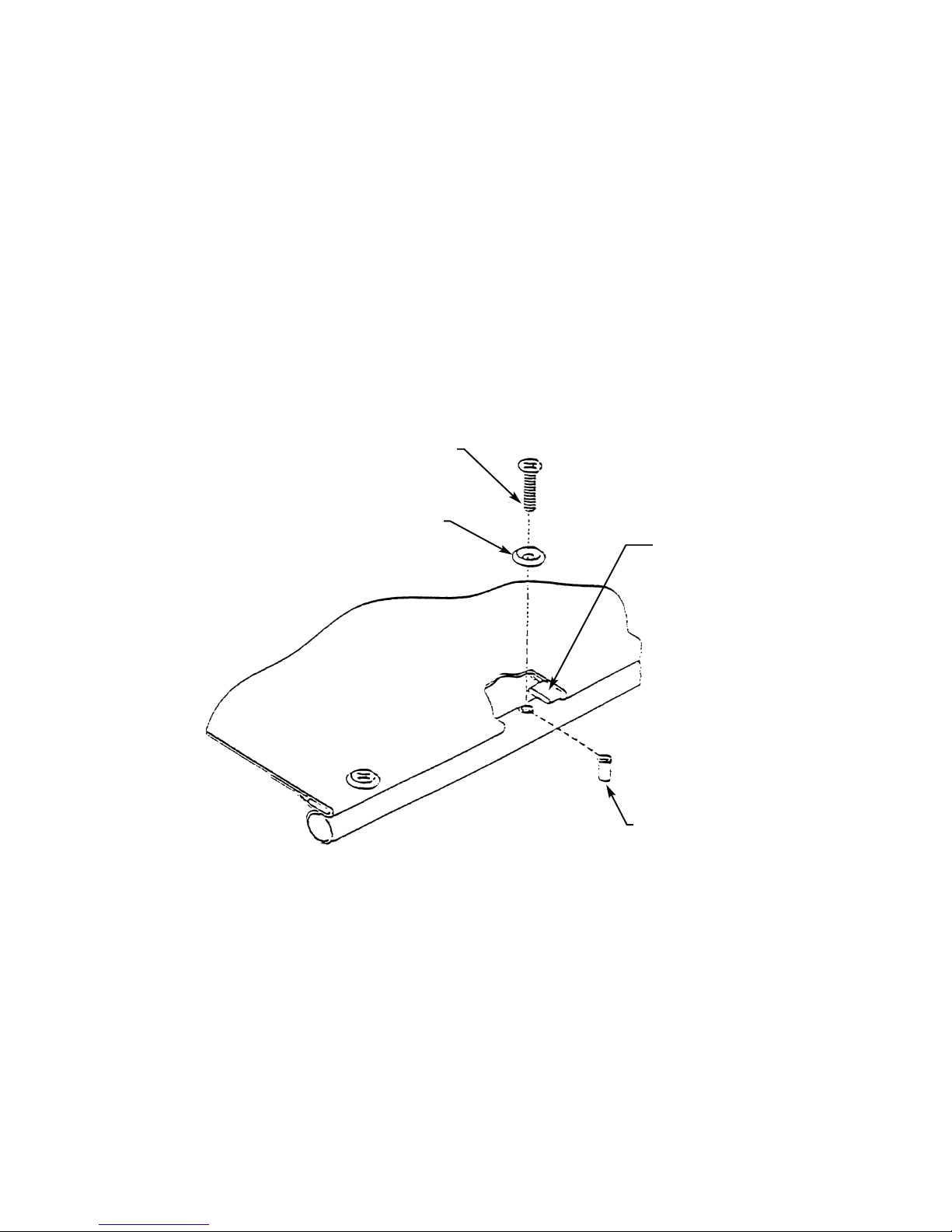
SECTION 6: UPHOLSTERY
6.1 Diagram
6.2 Parts Lists
GZF No RJ No
Backrest Fabric Black Nylon 137 to 140 295/17/SIZE
Seat Fabric Black Nylon 133 to 136 295/12/SIZE
Skirt Guard Fabric Left Black Nylon 295/19/L
Skirt Guard Fabric Right Black Nylon 295/19/R
Reinforcing Bar TSD8074
No. 10 UNF 3/4 inch long raised countersunk screw zinc plated F15
NO. 10 Flanged screw cup F38
No. 10 Avdel UNF Nutser t
09657/01014
Page 1 of 2
BACKREST FABRIC 295/17
LEFT SIDE PANELS 295/19/L
RIGHT SIDE PANEL 295/19/R
REINFORCING BAR TSD 8074
SEAT FABRIC 295/12
No.10 UNF x 3/4" RAISED
COUNTERSUNK SCREW F15
No.10 UNF FLANGED SCREW CUP F38
No.10 AVDEL UNF NUTSERT
09657/01014
No.10 UNF x 3/4" RAISED
COUNTERSUNK SCREW F15
No.10 UNF FLANGED SCREW CUP
F38
No.10 AVDEL UNF NUTSERT
09657/01014
-9-
6.3 Inspection
Check for staining, wear, tear and stitching.
Check nut inserts in frame for security and stripped threads.
Check securing screws for bending and stripped threads and burrs.
Cushions (if fitted);
Check cushions for staining, wear, tear and stitching.
6.4 Fabric Removal
If the Nutserts need replacement, use Avdel recommended tooling.
6.5 Fabric Fitting
Punch holes in seat fabric using holes in the reinforcing bar as a template.
Punch holes in skirt guard fabric commencing from rear of seat tube using holes in seat
tube as a template.
Slide the reinforcing bar into the stitched section on each side of the seat fabr ic.
Fit the countersunk screws through the flange cups and fit through holes in the side skirt,
seat fabric and reinforcing bars.
Place the fabric on the seat and tighten screws taking care not to exert excessive force to
flatten the flange cup or cut into the fabric.
Section 6 Page 2 of 2
REINFORCING BAR
No.10 UNF x 3/4"
COUNTERSUNK SCREW
FLANGED SCREW CUP
No.10 UNF AVDEL NUTSERT

SECTION 7: ARMRESTS
7.1 Diagram
7.2 Parts Lists
GZF No RJ No
Armrest Assembly complete Left 295/32/L
complete Right 295/32/R
Armrest Tube Left 295/29/L
Right 295/29/R
Armrest Pad 295/32/3
Armrest Socket 295/33
Tube Plug 2460
M5 x 20 Button head screw zinc plated F200
1 1/2 inch x 1/4 inch UNF Hex head bolt zinc plated F9
1/4 inch UNF Self locking thin nut zinc plated P92
M5 Nutsert L Flange steel zinc plated 09418/02517
7.3 Inspection
Check armrest pads for excess wear or damage.
Ensure armrest sockets are secure to backrest tube.
Ensure armrest assembly locates in socket without excessive movement.
Check nut inserts in frame for security and stripped threads.
7.4 Armrest Replacement
If the armrest pad is worn or becomes damaged a replacement ar mrest tube with pad
should be fitted.
-10-
ARMREST TUBE
295/29/L
295/29/R
1 1/2 x 1/4" UNF HEX HEAD BOLT
ZINC PLATED F9
M5 x 20 BUTTON HEAD SCREW
ZINC PLATED F200
M5 FLANGED STEEL NUTSERT
ZINC PLATED 09418/02517
1/4" UNF THIN NYLOC NUT ZINC
PLATED P92
ARMREST SOCKET 295/33
TUBE PLUG
2460
ARMREST PAD
295/32/3

-11-
SECTION 8: METEOR FOOTREST ASSEMBLY
8.1 Diagram
Page 1 of 5
22
LEFT
RIGHT
295/62
RH FOOTREST HANGER
ASSEMBLY COMPLETE
COMPRISING ITEMS 1 TO 6
INCLUSIVE 22 AND 23
295/63
RH FOOTREST SUPPORT
ASSEMBLY COMPLETE
COMPRISING ITEMS 7 TO 18
INCLUSIVE
295/64
LH FOOTREST SUPPORT
ASSEMBLY COMPLETE
COMPRISING ITEMS 7 TO 11
INCLUSIVE AND 19 TO 21
INCLUSIVE
295/61
LH FOOTREST HANGER
ASSEMBLY COMPLETE
COMPRISING ITEMS 1 TO 6
INCLUSIVE 22 AND 23
22
5
4
3
1
8
7
10
10
19
18
17
14
13
12
9
10
11
10
7
8
1
2
3
4
5
16
15
11
21
20
9
2
6
6
23
23

-12-
8.2 Parts List
GZF No RJ No
Footrest Hanger Assembly complete LH
comprising items 1-6 inclusive, 22 and 23 295/61
Footrest Hanger Assembly complete RH
comprising items 1-6 inclusive, 22 and 23 295/62
1 Footrest Hanger 295/3
2 Spring Pin F42
3 Sliding Peg Plunger SF194
4 Plunger Spring SF71
5 Sliding Peg SF163
6 Sliding Peg Handle SF614
22 Spring Pin F43
23 Plastic Cap 16313
Footrest Support Assembly complete RH
comprising items 7-18 inclusive 295/63
Footrest Support Assembly complete LH
comprising items 7-11 inclusive and 19-21 inclusive 295/64
7 Footrest Stem 295/11
8 Spring Catch MP222/M
9 1/4 inch UNF x 1 1/2 inch Bolt zinc plated F9
10 6mm Washer zinc plated Q79
11 1/4 inch UNF Nyloc Nut zinc plated P90
12 Footplate Hinge 295/14
13 Footrest Tube 295/13A
14 Footrest Bar 295/13B
15 1/4 inch UNF x 1 1/2 HT Hex Head Bolt zinc plated F9
16 6mm Washer zinc plated Q79
17 Location Tube 295/16
18 Spring Latch SC02108
19 Ball Stud SBV2141
20 4BA x 3/8 inch Cap Head Screw zinc plated SCR0760
21 Footplate Location 295/15
8.3 Inspection
Ensure that all moving parts of the footrest hanger (1), spring pins (22) and sliding pegs (5)
do not bind and are easy to operate.
Check that the sliding peg (5) locates into its hole on the wheelchair frame.
Check that all bolts, both locking (15) and pivotal (9) are secure.
Check that there is not excessive play in the footplate hinge (12) or footplate location (21).
Check that the paintwork is not scratched or chipped.
Section 8 Page 2 of 5

8.4 Footrest Dismantling
Unclip the footrest bar (14) from the footplate location ball stud (19).
Remove each footrest hanger from the frame by sliding the peg handle (6) forward.
Rotate the footrest hanger away from the wheelchair frame and at the same time lift the
hanger upwards to remove.
8.5 Left Hand Footrest Hanger Assembly Dismantling
Depress the spring catch (8) and remove the footrest stem (7) from the footrest hanger (1).
Hook the spring catch (8) and withdraw from the footrest stem (7).
Release the pivot bolt (9) and withdrawn to release the footplate location (21) from the
footrest stem (7).
Release the cap head screw (20) to remove the ball stud (19).
8.6 Right Hand Footrest Hanger Assembly Dismantling
Depress the spring catch (8) and remove the footrest stem (7) from the footrest hanger (1).
Hook the spring catch (8) and withdraw from the footrest stem (7).
Release the pivot bolt (9) and withdraw to release footplate hinge (12) from the footrest
stem (7).
Release the two mounting bolts (15) and separate the footrest bar (14) from the footplate
hinge (12), footrest tube (13) and location tub e (17). The spring latch (18) can then be
removed from the location tube (17).
8.7 Footrest Assembly
To reassemble reverse 8.4, 8.5 and 8.6 procedures.
The mounting bolts (15) should be inserted using thread locking compound grade 241.
Ensure that all washers are inserted correctly in accordance with diagram 8.1.
All 1.4 inch bolts are to be torqued to 10 lbs/ft (13 Nm).
-13-
Section 8 Page 3 of 5

8.8 MINI-METEOR FOOTREST ASSEMBLY
8.8.1 Diagram
8.9 Parts List
GZF No RJ No
Footrest Hanger Assembly complete RH
comprising all items listed below 302/12
Footrest Hanger Assembly complete LH
comprising all items listed below 302/13
Footrest Hanger Assembly excluding Footplate Assembly 302/3
Footplate RH 300/8/17-10R
LH 300/8/17-10L
Footplate Support 300/8/16
1/4 inch UNF x 1 1/2 inch Hexagon Head Bolt zinc plated F9
M6 Washer Q79
1/4 inch UNF Locknut zinc plated F25
Spring Pin F42
Sliding Peg Plunger SF194
Plunger Compression Spring SF71
Sliding Peg SF163
Sliding Peg Handle SF164
Plastic Cap 161313
-14-
Section 8 Page 4 of 5
SLIDING PEG HANDLE
SF164
SLIDING PEG
PLUNGER SF194
FOOTREST HANGER
ASSY 302/3
1/4" UNF LOCKNUT ZINC PLATED F25
M6 WASHER Q79
FOOTPLATE SUPPORT 300/8/16
1/4" UNF x 1 1/2" HEX HEAD
BOLT ZINC PLATED F9
FOOTPLATE 300/8/17-10R
FOOTPLATE 300/8/17-10L
FOOTREST HANGER ASSEMBLY
RH 302/12
LH 302/13
SLIDING PEG SF163
PLUNGER COMPRESSION
SPRING SF71
PLASTIC CAP 161313
SPRING PIN F42
SPRING PIN F42

-15-
8.10 Inspection
Ensure that all moving parts of the footrest hanger assembly do not bind and are easy to
operate.
Check that the sliding peg locates into its hole on the wheelchair frame.
Check that all bolts are secure.
Check that the paintwork is not scratched or chipped.
8.11 Footrest Dismantling
Remove each footrest hanger from the wheelchair frame by sliding the peg handle forward.
Rotate the footrest hanger away from the wheelchair frame and at the same time lift
upwards to remove.
Release the 1/4 inch UNF bolts to remove the f ootplates from the f ootrest hanger assemb ly.
8.12 Footrest Assembly
To reassemble, reverse 8.11 procedure.
Ensure that all washers are inserted correctly in accordance with diagram 8.8.1.
All 1/4 inch bolts are to be torqued to l0 lbs/ft (13 Nm).
Section 8 Page 5 of 5

-16-
SECTION 9: METEOR BRAKE ASSEMBLY
9.1 Diagram
9.2 Parts List
GZF No RJ No
Brake Assembly complete RH 26085
LH 26086
Comprising:
1 Lever 295/59
2 Brake Shoe Bar
3 M6 x 26mm Button Head Screw
4 Handle Assembly
5 Brake Knob
6 No.10 x 5/8 inch long Screws
7 Small Link
8 Disc Springs
9 M5 Self-locking Nuts
10 Large Brake Block Clamp
11 4mm x 20mm Spiral Pin
12 M6 x 25mm Socket Head Cap Screws
13 Small Brake Block Clamp
14 M6 x 30mm Socket Head Cap Screws
Page 1 of 4
5
BRAKE ASSEMBLY
RH 26085
LH 26086
9 11 124876
2 1 1 10 13 14

9.3 Inspection
The Brake Assembly must be fir mly attached to the wheelchair frame and easily operable.
The force required to apply the brake is min/max: 5 lbs (22N)/10 lbs (44N).
If the brake is difficult to apply it must be replaced.
The force required to revolve the wheel against the brake must exceed 30 lbs(132N) at the
wheel rim. If it does not, check that the tyre pressure is correct as 50psi (340 Kilopascals).
9.4 Brake Assembly Removal
Release the two socket head cap scre ws in the br ak e clamp to remo ve the brake assembly.
9.5 Brake Assembly Fitting
Position the br ake assemb ly on the wheelchair frame bef ore finally tightening the two sock et
head cap screws ensuring that the brake is effective. Apply Loctite thread locking
compound and tighten the two socket head cap screws in the clamp to 10-12 lbs/ft (13.55-
16.26 Nm).
-17-
Section 9 Page 2 of 4

SECTION 9.6: MINI-METEOR BRAKE ASSEMBLY
9.6.1 Diagram
9.7 Parts List
GZF No RJ No
Brake Assembly complete RH 302/46R
LH 302/46L
Brake Handle 302/48
Red Vinyl Sleeve F3-2-S14R
Hinge Block 287/100D
Brake Pin 287/100G
Link Assembly 287/100J
1/4 inch UNF Locknut zinc plated P92
M6 Nylon Washer F86
1/4 inch UNF x 1 1/4 inch Hex Head Bolt zinc plated F6
1/4 inch UNF Nyloc Nut zinc plated P96
1/4 inch Shakeproof Washer zinc plated F98
-18-
Section 9 Page 3 of 4
RED VINYL SLEEVE F3-2-S14R
MINI-METEOR BRAKE ASSEMBLY
LH 302/46L
RH 302/46R
BRAKE HANDLE 302/48
BRAKE PIN 287/100G
1/4" UNF LOCKNUT
ZINC PLATED P92
1/4" UNF LOCKNUT P92
1/4" UNF NYLOC NUT
ZINC PLATED P96
1/4" UNF x 1 1/4 HEX HEAD
BOLT ZINC PLATED F6
M6 NYLON WASHER F86
M6 NYLON WASHER F86
M6 NYLON WASHER F86
M6 NYLON WASHER F86
1/4" SHAKEPROOF WASHER ZINC
PLATED F98
LINK ASSEMBLY 287/100J
HINGE BLOCK 287/100D

-19-
9.8 Inspection
The Brake Assembly must be fir mly attached to the wheelchair frame and easily operable.
The force required to apply the brake is min/max: 5 lbs (22N)10 lbs (44N).
If the brake is difficult to apply it must be replaced.
The force required to re volve the wheel against the brake must exceed 30 lbs (132N) at the
wheel rim. If it does not, check that the tyre pressure is correct as 50psi (340 Kilopascals).
9.9 Brake Assembly Removal
Release the two hex head bolts to remove the brake assembly.
9.10 Brake Assembly Fitting
Position the brake assembly on the wheelchair frame.
Locate the two bolts through the recess, fit washers and nyloc nuts.
Before tightening the two bolts ensure that the brake is effective.
Tighten the two bolts to 10-12 lbs/ft (13.55-16.26 Nm).
Section 9 Page 4 of 4

SECTION 10: BACKREST ASSEMBLY
10.1 Diagram
10.2 Parts List
GZF No RJ No
Backrest Assembly 295/9
Backrest Fabric 295/17
End Cap 2460
Tapered Plug WS511
No. 10 Avdel UNF Nutser t 09657/01014
No. 10 Flanged Screw Cup F38
2 BA x 3/4 inch raised head
Pozidrive CSK Screw black zinc plated F102
-20-
Page 1 of 2
HAND GRIP M57
PUSH HANDLE 295/10
1/4 UNFx1 1/8" HEX HD BOLT
ZINC PLATED F6
No.10 UNF AVDEL NUTSERT 09657/01014
No.10 FLANGED SCREW CUP F38
2 BA x 3/4" RAISED HEAD POZI DRIVE
CSK SCREW BLACK ZINC PLATED F102
M5 FLANGED STEEL NUTSERT ZINC
PLATED 09418/02517
SAME FOR LEFT & RIGHT
BACKREST TUBE
BACKREST ASSEMBLY 295/9
BACKREST 295/17
TAPERED PLUG WS511
END CAP 2460
1/4 UNF THIN LOCKNUT
ZINC PLATED P90

10.2 Parts List (Continued)
GZF No RJ No
Push Handle 295/10
Hand Grip M57
1/4 inch UNF x 1 1/8 inch Hexagon Head
Set Screw zinc plated F6
1/4 inch UNF Thin Nyloc Nut P90
M5 Nutsert L Flange Steel zinc plated 09418/02517
10.3 Inspection
Check fabric for staining, stretching, wear, tear and stitching.
Check nut inserts in frame for security and stripped threads.
Check securing screws for bending, any stripped threads and burrs.
Check that all end caps and tapered plugs are fitted.
Ensure that the hand grips are firmly attached to the push handles, if fitted.
Check that the Velcro retains skirtguards in position.
10.4 Fabric Removal
Release the four countersunk fixing screws and flanged cup washers.
Slide the fabric downwards to remove from the backrest assembly.
If the nutserts need replacement use Avdel recommended tooling.
10.5 Fabric Fitting
Slide the backrest fabric onto the ver tical backrest tubes.
Fit the countersunk fixing screws through the flanged cup washers and pass through the
holes in the fabric.
Tighten the screws taking care not to exer t excessive force to flatten the flange cup washer
or cut into the fabric.
10.6 Push Handle Fitting
Remove the end caps from the backrest tubes, and inser t the push handles.
Pass the setscrew through the backrest tube and push handle.
Attach the nut and tighten until it is a snug fit against the backrest tube.
10.7 Push Handle Removal
Reverse 10.6 procedure.
-21-
Section 10 Page 2 of 2

SECTION 11: FRAME AND CROSS BRACE ASSEMBLY
11.1 Diagram
-22-
Page 1 of 4
3
5
10
12
13
14
6
1
21
10
18
20
19
17
22
10
9
15
16
8
11
2
10
11,1
4
7

11.2 Parts List
GZF No RJ No
1 Side Frame Assembly 295/2L
2 Side Frame Assembly 295/2R
3 RH Seat Tube & Cross Brace Assembly 295/4
4 LH Seat Tube & Cross Brace Assembly 295/5
5 Cross Brace Stay Assembly 295/6
6 Side Frame Pivot Bush 295/23
7 Seat Tube Plug 5520
8 Tube Plug 2460
9 Seat Location WS151
10 1/4 inch Plain Washer Q79
11 1/4 inch Nyloc Nut P90
12 1/4 inch UNF x 1 3/4 inch Hexagon Head
Bolt, zinc plated F11
13 8mm Form B Plain Washer, zinc plated F141
14 5/16 inch UNF x 2 1/2 inch HT Hexagon Head
Bolt, zinc plated Q707
15 5/16 inch UNF Nyloc Nut, zinc plated P113
16 Spring Catch MP222/M
17 Wheel Mounting Block 295/7
18 1/4 inch UNF x 2 1/4 inch HT Hexagon Head
Bolt, zinc plated Q704
19 Wheel Insert Bush complete with wheel assembly )
20 Washer 16mm ) WHLQRB12
21 Nut 16mm x 1mm )
22 Anti-tipping Assembly 295/8
-23-
Section 11 Page 2 of 4

11.3 BACKREST LOCKING ASSEMBLY
11.3 Diagram
11.4 Parts List
GZF No RJ No
1 Lock Pin TSD1306
2 Plunger Spring TSD1269
3 Lock Lever TSD1323
4 Plain Washer Q5
5 3/16 Star Lock Washer F37
11.5 Inspection
Examine the structure of the frame for damage.
Check pivot points for undue slackness due to loose nuts and bolts or worn parts.
Check that the cross braces fold with ease without binding.
Check all joints for fractures.
Check that there is no misalignment of the castor mounting tubes or thread bushes.
Check all tube plugs, side frame pivot bushes and seat location mouldings for integrity,
replace if missing or broken.
Check that the lock lever rotates easily and that the lock pin moves in and out of the side
frame rear tube.
11.6 Frame Dismantling
Remove the upholstery as described in Section 6.
Remove the castors as described in Section 12.
Remove the wheels as described in Section 13.
Release the cross brace stay pivot bolts (12) and withdraw.
Release the main cross brace pivot bolt (14) and withdraw from cross brace assemblies.
Remove the brake assemblies as described in Section 9.
Release the wheel mounting block bolts (18) and remove the wheel mounting blocks (17).
Squeeze the spring catch (16) to remove the anti-tipping rollers (22) and then withdraw
the catch using a hook.
-24-
Section 11 Page 3 of 4
2
1
3
4
5

-25-
11.7 Frame Assembly
Reverse 11.6 procedure.
All bolts are to be tightened to the following values:
1/4 inch UNF 10 lbs/ft (13 Nm)
5/16 inch UNF 25 lbs/ft (33 Nm)
The mounting bolts (15) and wheel insert bush (19) should be inserted using thread locking
compound grade 241.
Ensure that all plastic bushes and mouldings are fitted and that the wheelchair frame folds
with ease on completion of assembly.
Section 11 Page 4 of 4

-26-
SECTION 12: CASTORS
12.1 Diagram 12.2. Diagram
12.3 Parts List
GZF No RJ No
125mm Wide Profile MCP M142
125mm Narrow Profile MCP M78
12.4 Inspection
Check for excessive wear in crown bearings and wheel spindle. Replace castor if
necessary.
Check condition of stud which screws into frame.
View frame and check both castor mounting tubes are at the same angle, checking for
frame distortion due to impact damage, replace if necessary.
Check tyre security to rim and for splits, cracking or damage.
Check security of castor.
Page 1 of 2
23.95mm
HEXAGON
23.95mm
HEXAGON
125
91
45
29
175 EFFECTIVE HEIGHT
PIN DIMENSIONS
M14 x 22 LONG
PIN DIMENSIONS
M14 x 22 LONG
125mm WIDE PROFILE
METEOR M142
125mm NARROW PROFILE
MINI-METEOR M78
108 SWIVEL
RADIUS
10
203 EFFECTIVE HEIGHT
105 SWIVEL RADUIS

12.5 Castor Removal
Unscrew the hexagon at the top of the castor s wivel using a 24mm (15/16 inch) AF spanner
until the castor is removed.
12.6 Castor Fitting
Apply Loctite thread locking compound Grade 241, or equivalent, to the thread and tighten
to 30-35 lbs/ft (40-47 Nm).
-27-
Section 12 Page 2 of 2

SECTION 13: QUICK RELEASE WHEEL
13.1 Diagram
13.2 Parts List
GZF No RJ No
Mini-Meteor
50cm (20") diameter detachable
wheel with spindle WH20BKALTTT
50cm (20") diameter pneumatic tyre 20TYR
50cm (20") diameter pneumatic tube 20TUB
50cm (20") diameter rim band tape 20TAP
Handrim suitable for 50cm (20") diameter wheel M190
12mm Quick Release Axle )
) complete with nut and washers WHLQRB12
12mm Quick Release Bush )
Meteor
61cm (24") diameter detachable
wheel with spindle WHL24BKALTTT
61cm (24") diameter pneumatic tyre 24TYR
61cm (24") diameter pneumatic tube 24TUB
61cm (24") diameter rim band tape 24TAP
Handrim suitable for 61cm (24") diameter wheel M191
12mm Quick Release Axle )
) complete with nut and washers WHLQRB12
12mm Quick Release Bush )
-28-
Page 1 of 3
16mm x 1mm THIN NUT ZINC PLATED
16mm WASHER
12mm QUICK RELEASE BUSH
WHLQRB12
12mm QUICK RELEASE AXLE
WHLQRAX12

-29-
Section 13 Page 2 of 3
13.3 Inspection
Check tyre for excess wear, splits, cracking and punctures.
(Puncture proof is available as an option).
Check for loose spokes and wheel to be true.
Check handrim for security and damage. ANY SHARP EDGES ARE DANGEROUS TO
THE USER.
Check axle for distortion.
Check that spindle plunger ends are screwed securely by gripping the ends lightly with
pliers and twisting in opposite directions.
Check that wheel insert bush is secure in the wheelchair frame by gripping ends lightly with
pliers and tightening to remove excessive play. If replacing apply Loctite thread locking
compound grade 241 or equivalent to the wheel insert bush thread.
Check for ease of wheel removal and replacement.
13.4 Wheel Removal
To remove the wheels, enure the brakes are not applied. With one hand hold the frame of
the wheelchair and with the other hand hold the spokes surrounding the hub and fully
depress the centre button. Pull the wheel away from the wheelchair and wheel insert bush.
Finally release the centre button.
13.5 Wheel Fitment
Lift the frame with one hand and the wheel in the other hand. Hold the spokes surrounding
the hub and fully depress the centre button. Insert the axle fully into the axle bush and
release the centre button. Ensure that the wheel is fully locked. Pull wheel outwards
without depressing the centre button. If located correctly, the wheel will not come off. If a
new axle has been fitted, length adjustment may be necessary.
QUICK RELEASE WHEEL BUSH
QUICK RELEASE WHEEL
PRESS
ANTI-TIP WHEELS
QUICK RELEASE SPINDLE
WHEEL HUB
SPOKES OMITTED FOR CLARITY

-30-
13.6 Adjustment
Assemble the wheel and spindle to the wheelchair. Opposing ball bearings on the spindle
must fully protrude past the inner face of the wheel bush. If they do not, slacken the nyloc
nut on the outer end of the spindle until this is achiev ed. Adjust the nyloc n ut until 1mm end
float (maximum). Excessive end float will cause the quick release spindle to bend. lack of
float may cause incorrect fitting of the wheel to the wheelchair.
13.7 Tyre Fitting
Fit a strong rim tape and check that the inside of the tyre and the rim well are clean. Put
one side of tyre onto rim, pass the valve of the tube through the rim and partially inflate the
tube until round in shape. Fit the remainder of the tube into the tyre.
Starting at the valve fit the other bead of the tyre into the rim working outwards with the
thumbs ensuring the tube is not pinched between the tyre and the rim.
Before inflating to the correct pressure, centre the tyre on the rim by lining up the bead line
on the tyre sidewalls with the edge of the rim. Spin the wheel and check that the tyre rides
evenly. If not then adjust the tyre again and recheck. When running centrally, inflate the
tyre to the correct pressure.
MAINTENANCE
It is essential that the quick release axle and bush are kept lightly lubr icated at all times to
ensure ease of action and it is recommended that a graphite-based lubricant is used for this
application.
Section 13 Page 3 of 3

TECHNICAL MANUAL
AMENDMENT RECORD
ISSUE SECTION DATE COMMENTS
AMENDED
-31-
 Loading...