

Page 1

ENGLISH
62
The use of economic and ecologic combustibles, the sweet warm of natural fire, the
sweet fragrance of the wood of our forests
are the qualities that make indispensable
wood fired cookers in every house.
Your choice fell upon a Rizzoli cooker, result
of a tradition started in 1912 when Carlo
Rizzoli began the production of wood fired
cookers with the typical style of the valley in
the dolomites. Year after year Rizzoli continued to refine its cookers using even more
advanced technologies, but without losing
contact with the elegance, the beauty and
the functionality of the original product.
1. INSTRUCTIONS
For the perfect working of Rizzoli cookers it
is necessary the correct placing and connection to the chimney, to AC power and to the
heating system if it is necessary. The installation normally ends when you light the cooker. It is necessary to predispose a duly made
chimney and well suited to the model you
chose. Before the connection of the cooker it is necessary to contact a local chimney
sweeper. The installation usually ends with
the lighting of the cooker and the verify of
the correct working.
It is necessary to use well dried and good
quality wood: it is also necessary to sweep
the chimney and the cooker regularly.
We recommend to read carefully the instructions in this booklet before starting to
use the cooker. Keep this booklet because it
could be useful in case of necessity.
Talking about the working and the installation of Rizzoli cookers, all the European
laws, national and local laws and rules must
be respected.
• Respect all the safety distances during the
installation of the cooker.
• The grids and the ventilation holes must
not be obstructed when you use the device.
• When using the cooker, some parts of the
device may be very hot, keep attention not
to lean and not to touch by hand hot parts
(frame, plate and doors).
• When you cook and generally when you
use the cooker you must not wear inflammable dresses. • Keep more attention in
presence of children.
• Do not lean to the cooker inflammable or
explosive materials, in particular curtains
or very close to it, inflammable flacons and
aerosol bombs.
• The fire door must always be closed except
for lighting operations, fire feeding operations and during the maintenance operations.
• Check regularly the fume-circuit and, the
chimney connection and the chimney itself. At least every six months of normal
use contact an experienced technician for
checking and cleaning of the wood fired
cooker.
• The plate must be cleaned regularly according to necessities after every use and
make regularly the specific maintenance.
• Before you go away for a long time, be
sure that the fire is terminated.
• The first lightings of the cooker and the
first seasonal lightings must be done with
temperate fire in order to prevent possible
breakings of the internal parts.
• After a long period in which you do not use
the cooker, check carefully that obstructions are not present and that the cooker
works regularly.
• Use only original or authorized spare parts.
• Do not make any unauthorized modification.
1.1 GENERAL INSTRUCTIONS
1.2 SAFETY INSTRUCTIONS
Page 2
ENGLISH
63
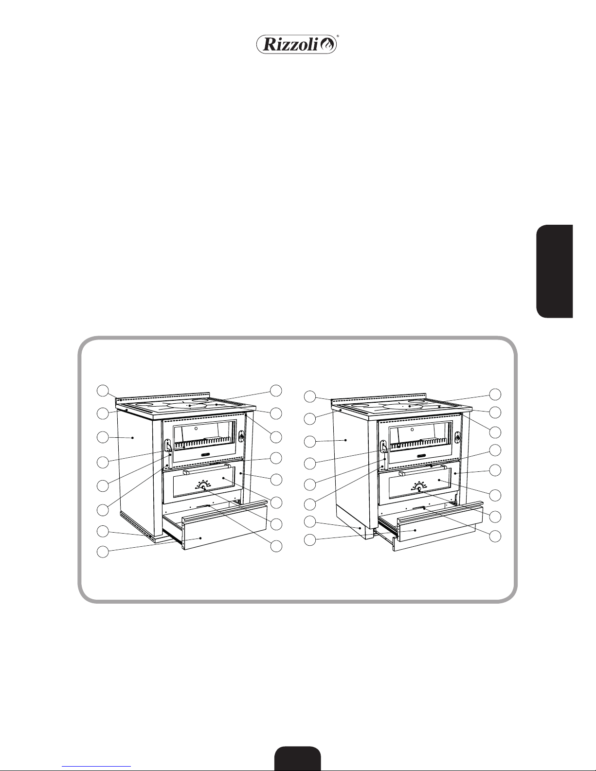
1 Riser
2 Frame
3 Side
4 Regulation of the fire door
cooling air
5 Fire door
6 Ash door
7 Starting air regulation
8 Plinth
9 Wood box
10 Oven door
11 Oven door glass
12 Thermometer
13 Flame keeper
14 Primary and secondary air
regulation
15 Plate
16 Disc or circles
Picture 1
Wood fired cookers are built to use wood
for burning. We recommend to use good
quality wood, dry, seasoned and possibly
broken.
Using good quality wood is warranty of
good heating power and avoid the forming
of carbon residuals and soot.
To avoid dissipation of energy and eventual deforming and damaging processes you
must not use excessive combustible.
The use of pre-compressed trunks and coal
is allowed only desultorily and with moderation, because the strong heating produced
may damage the internal refractors, the
wood-carrying grill, the oven and in general
all the parts directly exposed to fire. Other combustibles and refuses, for example
plastic, enamelled or treated wood or car-
ton must not be burned. Using this materials cause serious damage not only to your
health and environment but also to wood
fired cooker and chimney. The cooker must
not be used as incinerator. It is recommended to use only the suggested combustibles
and not liquid combustibles.
1.3 RECOMMENDED COMBUSTIBLES
1.4 OTHER COMBUSTIBLES
1.5 PARTS OF THE COOKER
3
13
6
5
8
9
2
1
3
13
6
5
8
9
2
1
14
12
11
10
7
4
15
16
14
12
11
10
7
4
15
16
Page 3

ENGLISH
64
Together with the wood fired cookers you
will find some accessories that simplify the
installation, the maintenance and the daily
use of the device.
• Ash drawer
• Glove
• Poker
• Scraper
• Plate care oil
• Plate cleaning oil
• Abrasive sponge
• Devices for the connection to the chimney,
variable depending on the model of cooker
• Oven grill
• Baking pan
• Instruction and maintenance booklet
• Green booklet and warranty certificate of
the wood fired cooker
• Certificate of quality for the refractory
bricks used
1.6 ACCESSORIES
2. INSTALLATION
Wood fired cookers are easy to install; anyway you must take some cares to avoid
damages due to unskillfulness. Before the
installation, we recommend to verify the
necessary space, the safety distances, the
correct predisposition of the chimney and
the possibility to make the necessary connections.
Do not drag the cooker, move it keeping it
lifted from the floor. The cooker must not
be moved making effort on the handrail or
on the handles.
2.1 GENERAL NOTES
For the cookers to be framed into furniture,
be sure that the minimum safety distances
are respected in presence of inflammable or
sensible to high temperatures materials (see
chapter 6.4). Rizzoli produces suited spacers
to make easier the installation of the cooker into furniture. The device must be placed
on a floor with enough load capacity. If the
existing building does not satisfy this condition, you must adopt different solutions (for
example you can use a plate to distribute
the load).
In case of floor made with inflammable
material, it is necessary to use a fireproof
protection for the floor in front of the fire
door. The cover of the floor must extend for
50 cm minimum in the front part and 30 cm
minimum
over the fire door on the sides.
We suggest not to install furniture on the
cooker. Eventually, the resistance of the furniture to heat must be guaranteed. In case
you want to use an aspiring hood, it is ab-
solutely necessary that it is resistant to high
temperatures. Rizzoli is specialized in the
production of aspiring hoods to be used together with the wood fired cookers.
If the cooker is framed between not sensible
to heating materials, it is necessary anyway
to keep a minimum distance of 1-2 mm to
allow the dilatation of the materials when
the temperature changes.
During the installation, you must be sure
not to obstruct the ventilation holes on the
top and in the plinth: this to prevent the
decadence of the isolating properties of the
cookers and, in general, of its correct working.
2.2 SAFETY DISTANCES
Page 4
ENGLISH
65
D
E
C
B
A
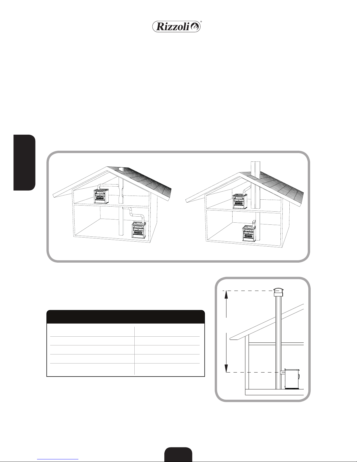
Picture 3 - Components of the chimney. A= cooker, B= conjunction, C= flue, D= chimney, E= reflow zone
Chimney has a main importance for the correct working of a wood fired cooker. Wood
fired cookers are built to insure the maximum efficiency, anyway the performances
of the cooker are deeply influenced by the
chimney. If the chimney has defects or does
not match the building laws, it is not insured
the correct working of the cooker. To build
the chimney you must use suitable materials, made to work with high temperatures
and according to fireproof laws: it is not important the kind of material, on condition
that it is right and that the chimney is isolated.
2.3 CHIMNEY
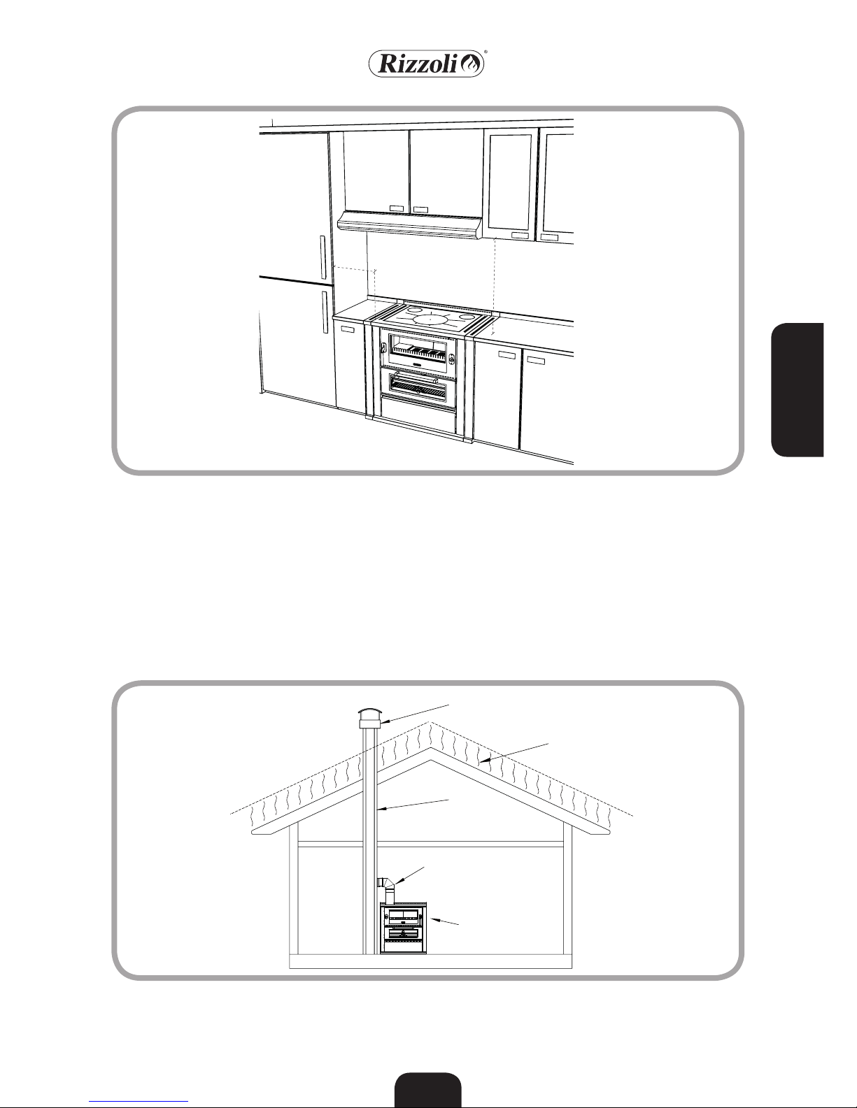
Picture 2 - Minimum safety distances when using suited spacers for the installation into furniture
Min.
20 cm
Min.
60 cm
Page 5
ENGLISH
66
Chimney must be dimensioned in a correct
way according to the type of cooker it is connected with, minding the environmental and
general conditions of the place in which it is
placed. The section of the chimney must permit the flow of the fumes produced by the
cooker without difficulties, but it must not
be too big otherwise the chimney will experience problems in heating itself and this may
generate problems like weak draught and
condensation. In table 1 it is indicated the
recommended diameter for the flue accord-
ing to the model of cooker and to the height
of the chimney (H). The height of the chimney must be enough to insure the draught
necessary to the chosen model. Bigger is the
height of the chimney, bigger is the draught;
if the chimney is lower than 4 metres, the
correct working of the cooker is not insured.
The chimney must not have tortuous parts,
horizontal parts or counterslope parts; the
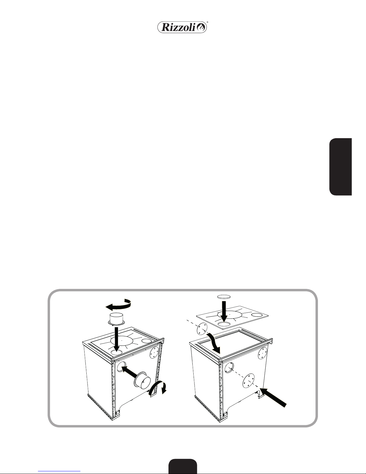
number of bends must be reduced to minimum. In picture 4 you can see some examples
of good and bad chimney connection.
2.4 DIMENSIONS AND CORRECT FORMS OF CHIMNEY
Picture 4 - Samples of correct and incorrect chimney connection
Picture 5 - H dimension for the sizing of
the flue
H
Table 1 - Indications for the dimension of the chimney according to its
height
entrance 140 mm
flue H < 4m
flue 4 m < H < 6m 180 mm
flue H > 6m 160 mm
Necessary depression 10 Pa
Model M 60 - M 70 - M 80
ø
ø
ø
ø
Draught not guaranteed
NO YES
Page 6
ENGLISH
67
The flue must be well isolated and circular
if possible. The flue must not have defects,
narrowings or losses. All the inspection
doors must be closed and well sealed. The
connection of other devices to the same
chimney is not allowed.
The chimney pot must have an exit section
doubled than the one of the chimney, in
order to make easier the exit of the smoke.
The chimney pot must be enough tall to
lean out over the reflow zone generated by
the roof: if you are not sure about this contact experienced technicians. If you are in a
windy place, it might be necessary to install
windproof devices.
The conjunction of the cooker to the flue
must be as short as possible and must not
have horizontal or not much inclined parts.
The counterslope parts are forbidden and
must be absolutely avoided.
Near the conjunction, inflammable materials must not be present. The conjunction
must not go inside the flue. To increase the
safety of the conjunction, we suggest to install a washer on the wall being sure that
the connection between the washer and
the chimney is walled and well sealed. Also
the connection between the cooker and the
conjunction must be fixed and sealed.
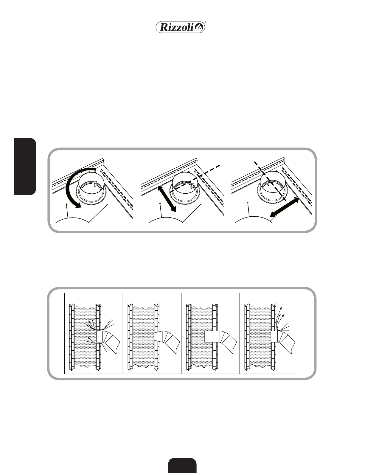
M Range models are endowed with the predisposition of the flue outlet in the upper
and rear parts, right or left. The choice of
the side must be done when ordering the
cooker. After the delivery, it is still possible
to change the position from right to left
and from left to right but it is necessary
to make some variations inside the cooker
in addition to the replacement of the flue
connector. The variation must be done by
experienced technicians. The use of the flue
outlet upper or rear is free and can be cho-
2.5 FLUE
2.6 CHIMNEY POT
2.7 CONJUNCTION
2.8 FLUE OUTLET PREDISPOSITION
Picture 6 - Multiflue cooker, predisposition of the correct flue outlet
Page 7
ENGLISH
68
2.9 CORRECT CONJUNCTION TO THE CHIMNEY
If the conduct of the chimney starts from
a lower floor than the connection point of
the cooker, it may be necessary to close the
conduct under the connection pipe with
fireproof materials. If you have the chimney
behind or up, you have to use the connector
with bayonet coupling. This must be insert-
ed and turned so that it can remain blocked.
This connector has a tolerance of about 1
cm to make the installation easier. The tolerance is available according to a single direction which depends on the orientation of
the connector (see picture 7).
The connection with the chimney must be
always well fixed and sealed, it must not
have narrowing and must not decrease the
usable section of the chimney (see picture
8). If near the cooker there is inflammable
material or high temperatures sensible, the
connection must be isolated and the safety
distances must be strictly observed.
Picture 7 - Tolerance for flue outlet on the top and back. The tolerance depends on the orientation of the connector.
+/-
10 mm
Y
X
+/-
10 mm
Picture 8 - Examples of correct and incorrect connection of the chimney
sen by the installer. Before connecting the
cooker, it is necessary to chose the correct
outlet and to verify that the other outlets
are closed, eventually using the caps given
as endowment of the cooker.
NO NO NO YES
Page 8

ENGLISH
69
The standard installation of the wood fired
cooker considers that the comburent air is
taken from the room where the cooker is
installed through the air intake of the cooker located in the plinth. In this case, in the
room must be always ensured the recycle
of fresh air, in particular if the room is small
and window and door frames are hermetic.
The correct flow of air in the room must be
ensured also in presence of other combustion based devices, aspiring hoods, chimneys
and vent-holes. The air intake in the room
must have a minimum surface of 80 cm2.
On demand, Rizzoli can give specific valves
which can allow the automatic opening of
the air intake only when it is necessary for
the correct working of the wood fired cooker, in order to warrant a maximum depression of 4 Pa in the place of installation.
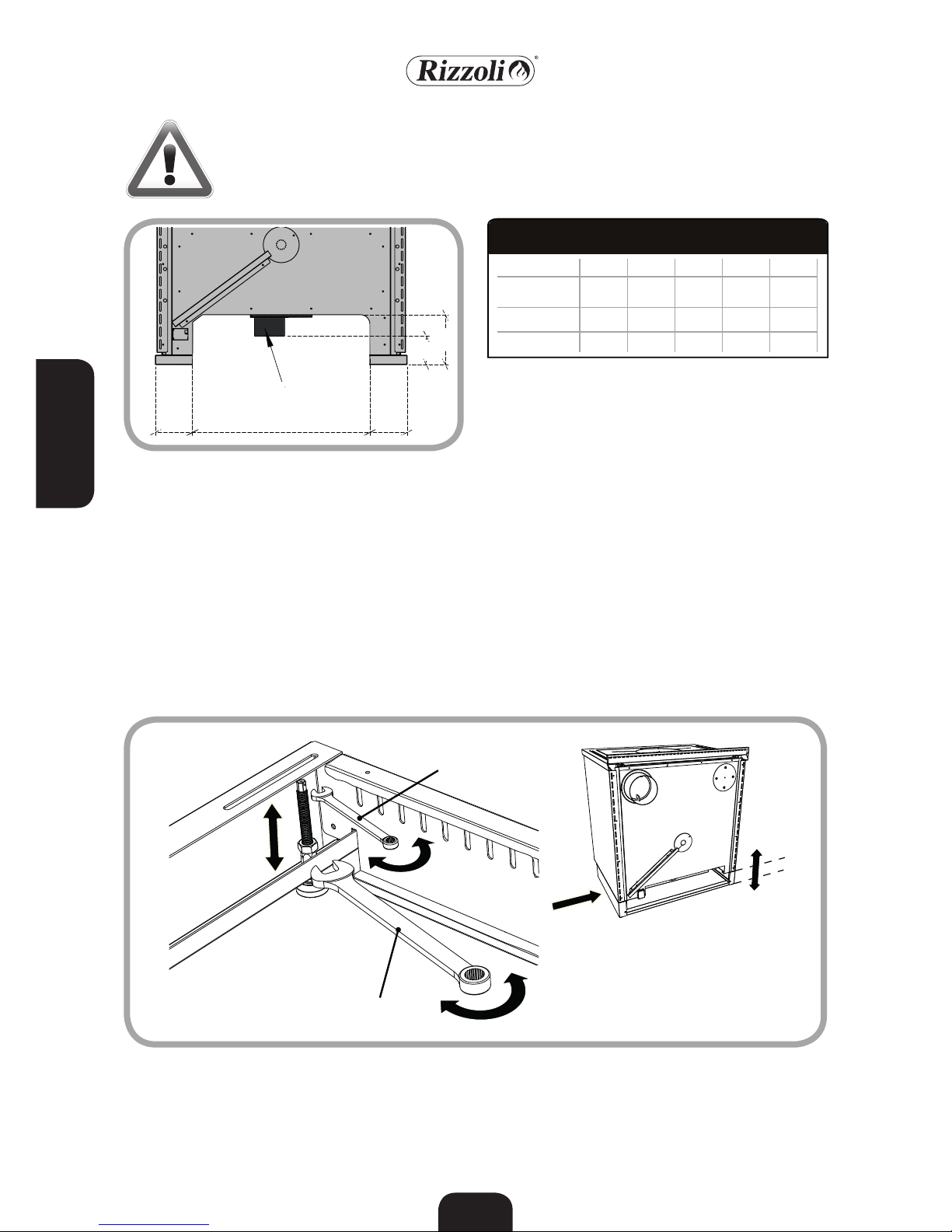
M Range wood fired cookers can also be
connected so that the comburent air comes
directly from outside. In this way, for the
wood fired cooker it is not necessary another air intake in the room of installation. To
make this it is necessary to prepare a conduct connected directly with the external
part of the house and make a direct connection with the air intake of the cooker. The
air intake of the cooker is located inside the
woodbox in correspondence of the combustion chamber. For the connection, we suggest to use a flexible pipe.
2.10 AIR INTAKE
A B C
Picture 9 - Installation with air intake in the room of installation and installation with air intake directly connected to the
wood fired cooker
Picture 10 - Possible connections of the air intake of the cooker. A = External air intake not connected B = External air
intake on the floor C = External air intake on the wall
To make the connection easier we suggest
to make the external air intake on the floor
in correspondence with the internal part of
the plinth, or on the wall through the rear
part of the cooker according to specifies
depending on the model (see picture 2 and
table 11). Are also possible other solutions
for the connection but they must be decided
together with Rizzoli.
Page 9
ENGLISH
70
C
A
B B
H
External air entry
Picture 11 - Rear sight of the plinth of the wood fired cooker
and specifies for the connection with the air
intake through the plinth.
WARNING! Aspiring hoods or extracting air fans in the room may generate
problems to the device if there is not a suited air intake or in case of air intake
sub-dimensioned.
C H
M 60 158 118 364 120 95
M 70 158 118 464 120 95
M 80 158 118 564 120 95
Models A B
ø
Measures
Table 2 - Dimensions for the connection of the external air
intake
The plinth of MZ Range cookers can be regulated in order to match the space in which
the cooker is inserted. It is possible to adjust the level of the cooker by operating on
the levelling pins that can be regulated in
height. To do this, it is necessary to remove
the woodbox and regulate singularly each
pin placed in the plinth near the corners, so
that the adjustment of the cooker is correct.
For the regulation of the pins, use an hex
key n.6: once you have reached the desired
height, fix the locknut with a n.13 key (see
picture 12). The pins have an excursion of 50
mm.
2.11 PLINTH REGULATION (MZ)
Picture 12 – Regulation of the height of the cooker with hex key through the levelling pins.
N.13
N.6
0-50 mm
Page 10
ENGLISH
71
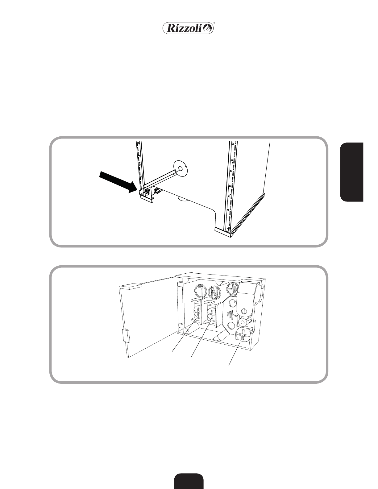
The electric connection of M Range cookers must be done in order to feed the lamp
of the oven. The connection to AC power
must be done by experienced people and
according with existing laws. The installer
is responsible of the correct connection according with safety rules. To make the connection, you have to connect an electric cable to the terminal board placed in the rear
side of the cooker. Must be done the correct
connections of line, neutral and earth as described in the picture 14.
The cable and every other electric device
added must be dimensioned for the electric
load to sustain and must not be in contact
with points 50° C hotter than ambient temperature.
2.12 ELECTRIC CONNECTIONS
Picture 13 - Position of the terminal board for the connection to the network
Picture 14 - Terminal board for the connection to the network: 1. Line 2. Neutral 3. Earth
1
2
3
Page 11

ENGLISH
72
The refractory mortar used for the internal
walling contains always a little moisture
that is eliminated after the first periods of
use: so it is normal that the first times you
light the cooker a little condensation is being generated.
All the refractory materials inside the cooker experience a settlement process that may
generate small holes on the bricks, such
holes do not preclude anyway the working
of the cooker.
Other settlements may involve other parts
of the cooker so during the heating and
cooling phases you might hear light noises.
These symptoms do not absolutely preclude
the use of the cooker and fading out till
disappearance with the constant use of the
cooker.
2.15 SETTLEMENTS
M Range cookers are predisposed with the
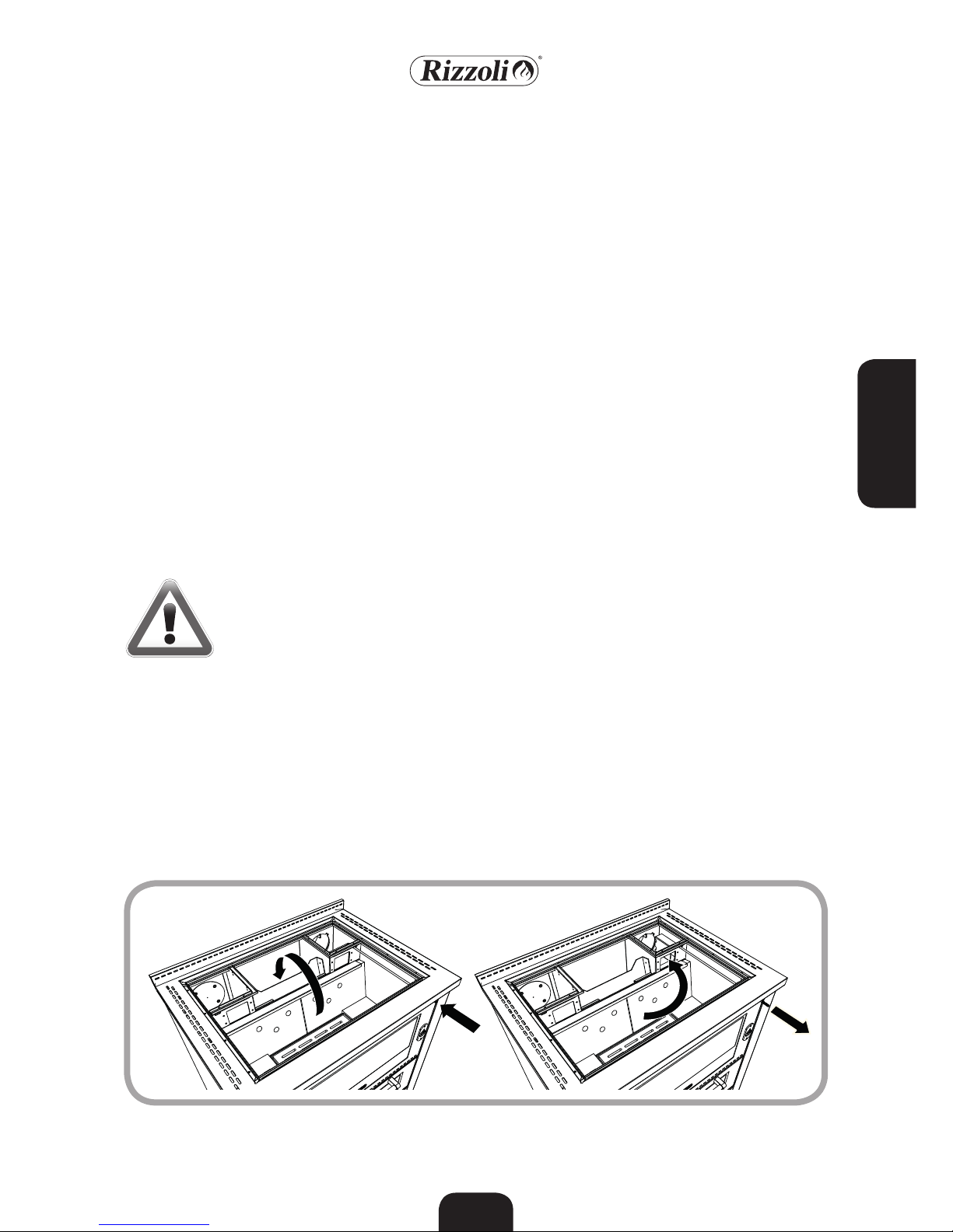
rightwards fire door opening, if not indicated leftwards at the order.
It is possible to change the opening also after the installation. The operation must be
done by experienced people.
2.13 DOOR OPENING VARIATION
Picture 15 – Variation of the door opening direction
Before starting to use the cooker, remove
the packaging materials in the oven and in
the wood box, remove the stickers and remove the plastic film in which is wrapped
the plate and remove with a rag the most
of the oil on its surface. We suggest to make
a first lighting of the cooker just to verify
the correct installation. The first lighting
must be done with moderate fire, using little wood broken in small pieces. In the next
lightings you can progressively increase the
load of combustible.
2.14 FIRST LIGHTING
Page 12
ENGLISH
73
3. USE
During the working, inside the cooker happens a combustive reaction of combustible
(the wood inserted in the combustion chamber) and burning (the oxygen present in the
air of the room in which the cooker is placed).
The wood fired cooker makes an intermittent
combustion: after the lighting, the combustion
goes on till the exhaustion of the combustible
but it can be maintained lighted by making another load of combustible and so on.
The maintenance of the combustion in time
is guaranteed by the correct working of the
chimney, which allows to evacuate the fumes
and in the same time to feed the flame with
comburent air. In this way, the features of the
chimney have a big influence on the correct
working of the cooker.
The combustion of wood requests that the air
flow inside the combustion chamber happens
in different points to obtain the maximum
efficiency. In particular, it is present a primary
air feeding that flows in the lower part of the
combustion chamber by the grill, and one or
more secondary air feedings that flow in the
upper part of the combustion chamber.
The primary air is the main air and regulates
the combustion speed. The secondary air allows the post-combustion of the fumes, generating further heating, knocking down the
amount of harmful gas and so improving both
the rendering and the impact on the environment. Once started the combustion it cannot
be interrupted in a safe way: it must be always
faded out naturally with the exhaustion of all
the combustible inserted.
3.1 WORKING OF THE COOKER
To allow an easier lighting of the cooker with
cold chimney, the M Range wood fired cookers
have two devices useful for starting. The starting key is ruled by a rod: extracting the rod, the
key opens. This creates a direct connection between the combustion chamber and the chimney, in order to obtain an improved draught.
The regulation of starting primary air al-
lows the direct entrance of air from the
room in which the cooker is installed to the
combustion chamber. When starting, it is
suggested to open both the devices that
later shall be closed when the fire will be
started for the normal working of the cooker.
The cooker is designed to be used with the
starting regulations closed, using they in differ-
Picture 16 - Starting key. With lever outside, the key is open and the starting is easier; with lever inside the key is closed
for the normal working
3.2 STARTING
WARNING! For the correct working of the wood fired cooker, verify that the comburent air flow through the intake of the cooker, the eventual air intake in the
room and all the aeration and ventilation grills are not obstructed.
Page 13
ENGLISH
74
Picture 18 – Regulation of the air intake lever. Picture 19 – The valve is open in correspondence of the
position marked by letter “A”, while is closed
in the position marked with letter “B”.
ent ways does not allow to the cooker to work
at its maximum and may cause damages. To
light the fire, you can use as combustible well
dried wood, broken thin, together with the
products available in commerce.
The combustion might be difficult as far as the
chimney is cold. The necessary time depends on
the chimney and the weather conditions.
3.3 AIR REGULATION
The air flow is ruled by an apposite valve
ruled by a lever placed below the oven door.
The valve is closed in the left position, is
open in the right position.
The position of the valve rules the comburent air inflow: more it is open, faster will
be the combustion and bigger will be the
power of the device.
When the cooker is not working the prima-
ry air must be closed, in order to limit the
undesired air flow that may cause an anticipated cooling of the device and the room.
This operation is particularly important
when the external air intake of the cooker
is directly connected.
Generally, for the good working of the device, we suggest to follow the indication for
the regulation of air reported in table 3.
Picture 17 – Regulation of starting primary air.
Table 3 - Cooker regulations in the different use conditions
Starting Open Open Open
Fast cooking Open Closed Closed
Slow cooking Half open Closed Closed
Fast heating Open Closed Closed
Slow heating Open at minimum Closed Closed
Condition
Air
regulation
Starting
air
Starting
key
B A
Page 14

ENGLISH
75
ATTENZIONE! Nel caricare la legna si raccomanda di mantenere una distanza
di alcuni centimetri tra il vetro della porta fuoco e il combustibile, in modo da
non esporre il vetro a temperature eccessive che lo potrebbero danneggiare.
The radiant plate is designed to allow a fast
and simple cooking. The hotter part is situated in correspondence with the hotplate,
this is the best part for placing a pot which
must get warm quickly. The external parts
of the plate are better to keep foods warm.
To obtain the maximum cooking speed you
have to use broken and thin wood and make
the regulations as described in the previous
chapters.
The plate must not be overheated and made
red hot because in such way the cooker may
experience damages without having no advantage for the cooking of foods.
3.4 PLATE COOKING
3.5 OVEN COOKING
The internal temperature of the oven depends on the combustion speed and on the
amount of combustible used. In particular,
working on the primary air regulator and so
on the speed combustion, you can obtain a
more steady combustion in order to avoid
sudden changes in temperature inside the
oven. If you want to heat the oven starting
from cold cooker, we suggest to increase
the temperature with bright fire and then
to decrease the speed combustion to keep
the temperature steady. The cookers are endowed with oven door with glass and thermometer that makes easier the temperature
controlling operations; the temperature indicated by the thermometer is approximate
ad is useful only for the cooking of foods.
When you do not use the oven, we suggest
to keep the oven’s door slightly open in order to let the heat go outside the cooker: an
overheating can damage the cooker.
For example, to cook the spineless person
biscuits in a correct way, it is necessary the
pre-heating of the oven at a temperature
indicated on the thermometer of 150°, keeping it in temperature by adding more or
less 1 Kg of wood for every charge as the
reaching of the coals. Once the temperature becomes stable, insert the baking-pan
with the biscuits in the central position in
the oven for 10 minutes, then extract the
baking-pan, rotate it and reinsert it again
in the central position for other 5 minutes.
In the end, remove the baking-pan from the
oven and leave cool the biscuits.
Cooking meals sometimes may generate a
steam excess inside the oven. In M Range
models there is a valve that allows to eject
the steam in excess. The valve is placed inside the oven on the lateral side towards
external and when necessary it shall be
regulated to open the air intakes. To avoid
possible burns, it is recommended to regulate the valve only before the lighting of the
cooker.
3.6 STEAM EXCESS VALVE
Picture 20 - Steam excess valve.
Page 15
ENGLISH
76
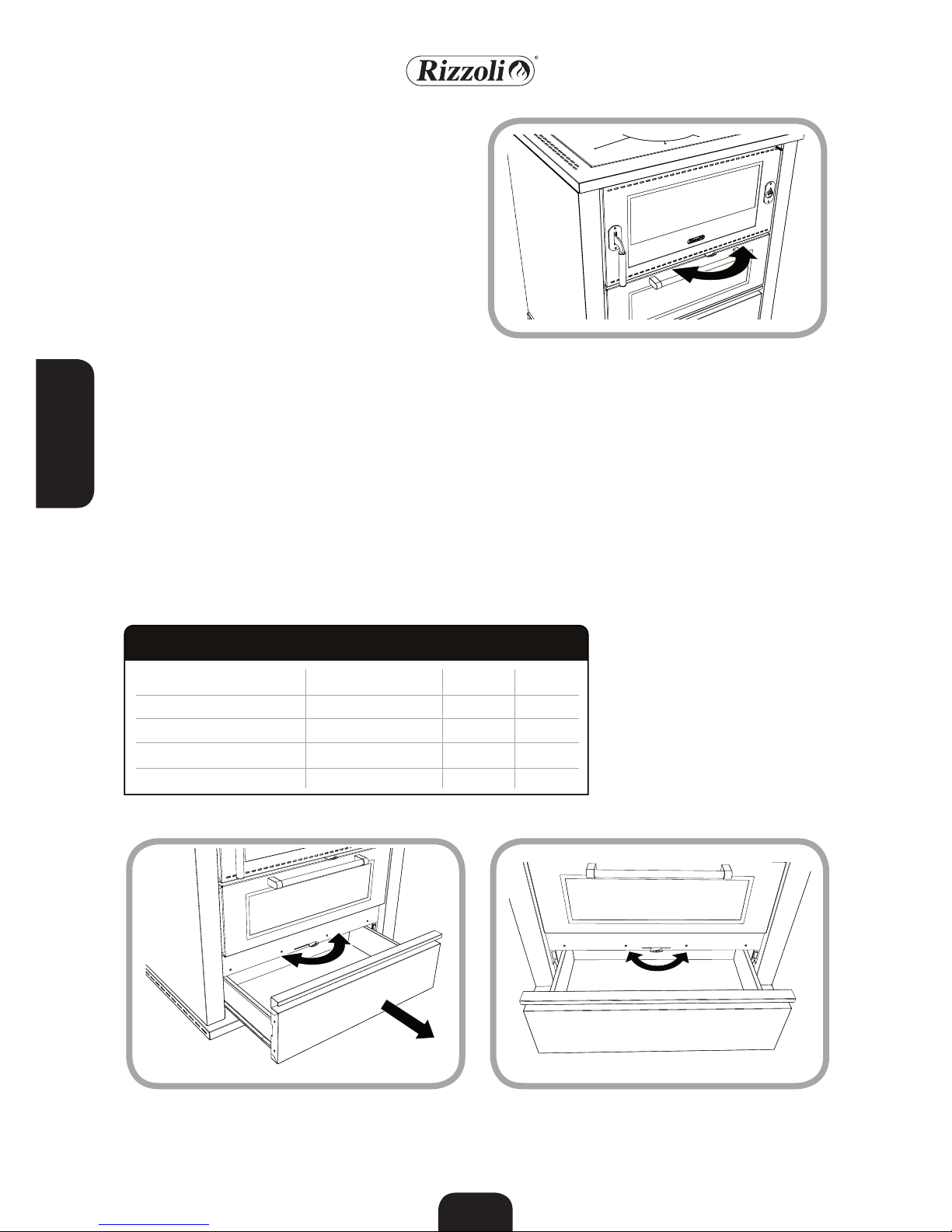
The wood box has a slide scroll system that
allows an assisted closure. When pushing
the box, it will close automatically.
For cleaning and for other reasons it could
be necessary to remove the wood box. To
make this you have just to extract the box
as the end of its track, then lift it softly and
at the same time extract it again. To set the
box to the initial position, repeat the same
operations inverted.
3.10 WOOD BOX
All the wood fired cookers have a telescopic pullout for endowed baking pan system.
In this way, it is possible to extract the baking pan without the necessity to sustain it,
ensuring a better practicality. On M range
cookers the telescopic pullout is placed in
a single position inside the oven, in the upper position. Anyway, in the lower position
is possible to insert the baking pan without
the telescopic pullout.
3.9 TELESCOPIC PULLOUT FOR BAKING PAN
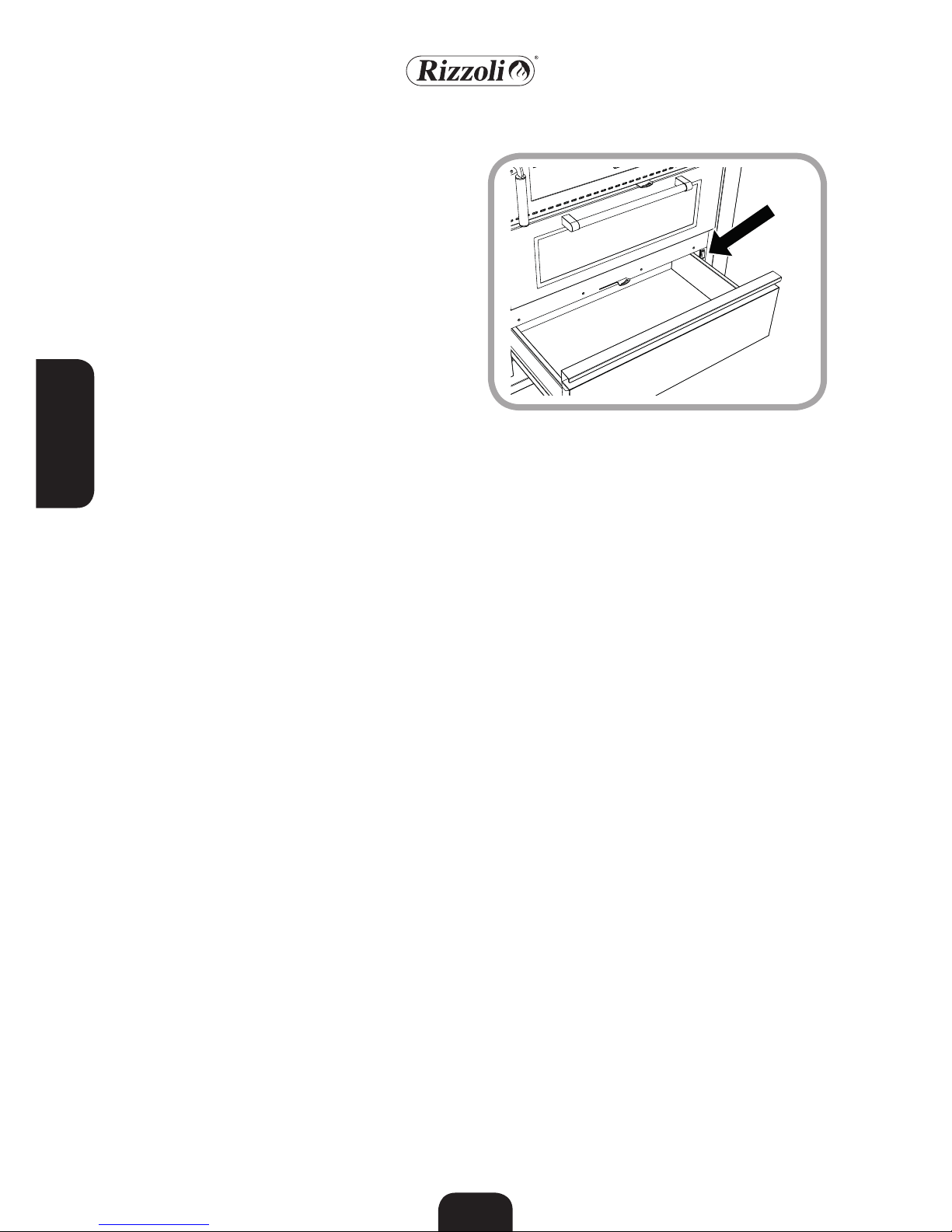
M Range cookers have a light inside the
oven which, together with the wide glass of
the door, allows to control the cooking process at sight without opening the door. The
lighting switch is located on a lateral upright you can find extracting the wood box.
3.7 OVEN LIGHT
Picture 21 - Switch to light the oven.
Wood fired cookers may be used also to heat
the ambient in which they are installed. The
heating comes from the plate and from the
front of the cooker. So the heating is effective just in the ambient in which the cooker
is inserted and in particular near the cooker
itself.
Also for the heating of an ambient you have
to start the cooker with bright flame with-
out using too much wood as long as a bed of
cinders is created: at this point you can put
more load of combustible inside the combustion chamber. For a bigger autonomy of
the cooker we suggest to use wood cut in
big pieces, hard if possible (ash-tree, beech,
hornbeam and others) and to make the regulations as described for the slow heating.
3.8 HEATING
Page 16

ENGLISH
77
Picture 22 – Fire door protection
On M Range cookers it is possible to have
on demand a steel protection which could
be placed on the fire door. This protection is
designed to shield the door when the cooking operations require the continuous presence of the user in front of the cooker or in
presence of children. In the other situations
the use of the protection depends on your
discretion. The placing operations must always be done with cold cooker opening the
fire door and placing the protection on the
door by joint.
3.11 FIRE DOOR PROTECTION (OPTIONAL)
On every cooker it is possible to use a stainless steel plate cover, made to cover the
plate in the periods in which the cooker is
not used. In this way you obtain an uniform
desktop. The plate cover must be used with
cold cooker. Before placing it, be sure that is
not present humidity, that the plate is clean
and that all the necessary maintenance is
done.
3.12 PLATE COVER (OPTIONAL)
Page 17
ENGLISH
78
4. MAINTENANCE
The cooker works better if all its parts are
without combustion residuals, a clean cooker will be less exposed to problems due to
wear. Cleaning frequency depends on how
much and how the cooker is used, as well as
on combustible quality.
4.1 CLEANING
Stainless steel parts have to be cleaned cold
with neutral detersives or with a specific
solution for stainless steel in case of hard
to remove dirt. Do not use at all abrasive
sponges that may scratch the surface. Dry
with a soft rag, following the glazing wise.
In particular situations, after the installation
or with the cooking of meals, an oxidised
superficial stratus may be generated, in particular on the inox stainless steel frame. Also
in these situations, an accurate cleaning will
restore the state of the product as it was
new.
On request Rizzoli gives specific products to
clean stainless steel. For enamelled or painted parts, do not use abrasive or aggressive
solution and in case of stains pour some oil
and wait while it absorbs the halo, then
clean with a soft rag. It is also recommended
to avoid the use of solvents or denatured alcohol on painted parts.
Every time you use the cooker you have to
clean the wood carrying grill before, at least
you have to clean the more rough deposits:
the holes of the grill should not be obstructed. To make this you can use the poker given
together with the cooker. If the grill is not
well cleaned, the flame could not be well
feed and so you could experience an irregular combustion. If the grill is being removed,
it must be placed in its housing with the flat
part turned upwards.
Every time you use the cooker you have to
check the ash box located under the combustion chamber. When the box is full, you
have to empty it. If you do not empty it, the
ash accumulates itself and makes the cleaning more difficult. In case of excessive cinders the flame could not be well fed and you
could experience an irregular combustion.
4.2 CLEANING THE VISIBLE PARTS
4.3 GRILL CLEANING
4.4 ASH BOX
WARNING! All these operations must be done with cold kitchen.
Page 18
ENGLISH
79
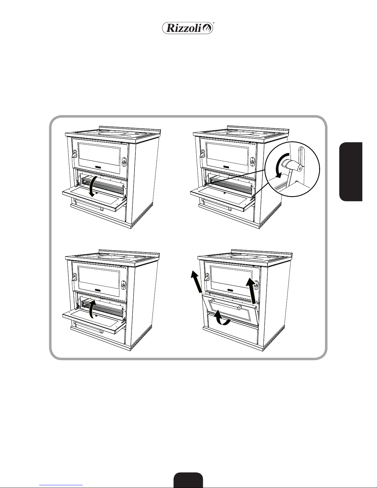
The oven must be cleaned with apposite
products available in commerce, to make
this operation easier you can remove the
oven door. To make this you have to open
the oven door and raise the tongues located
on the door’s hinges. Now, you can unhook
the door from the cooker closing it softly
and lifting the lower part of the door. To
hook again the door to the cooker, make
the same operations reversed. Also the grids
on the sides could be removed to make the
cleaning more simple.
4.5 OVEN CLEANING
Picture 23 - Unhooking the oven door from the cooker
A B
C D
Page 19

ENGLISH
80
In the wood fired cookers, the combustion
fumes are forced to turn completely around
the oven. For this reason, M Range wood
fired cookers are endowed with a double
inspection to clean the fume-circuit. The
cleaning must be done at least after six
months of normal use of the cooker as the
cleaning of the chimney, according to the
use it might be necessary a more frequent
cleaning.
To access the first inspection, it is necessary
to lift the two plates placed below the ash
drawer. The removal of the plates could be
easier using a sharp tool inserted in the apposite hole in the centre of each plate (see
pictures 24 A and B).
To allow the removal of combustion residuals also in the space below the oven, there
is a mobile platform inside the oven. To
proceed with the cleaning of the second inspection, it is suggested to remove the oven
door (see chapter 4.5), lift the platform, remove the carbon residuals using the scraper
and then close it, paying attention to not
damage the fiber gasket (see picture 24 C
and D).
The eventual presence of holes inside the
refractory material predisposed at the base
of the fume-circuit is normal and does not
preclude the working of the cooker.
4.6 FUME-CIRCUIT INSPECTION
Picture 24 – Fume-circuit inspection.
A B
C
D
Page 20
ENGLISH
81
Radiating plates in special steel need regular
maintenance, in particular they need cleaning after every use that brings moisture or
dust on the plate itself. With cold cooker
you have to remove all the pots and boilers
that could maintain moisture on the plate.
Together with the cooker are given two exclusive products, studied for the cleaning
and the maintenance of the plate: they are
an abrasive sponge, a cleaning oil and a protective oil, on how to use them please read
the instructions written on the bottles.
The plates are all worked in with non acid
anti-corrosion oil. The daily use of the cooker deletes this oil layer and so the contact
with water may cause small rusty stains. In
this case you have to wipe the plate with
a rag soaked with the oil given together with the cooker. If the rusty stain is not
being cleaned, you could have to wipe the
plate with a lightly abrasive paper or with
the abrasive sponge given together with
the cooker. To restore the protecting layer
wipe the plate with little oil. Do not clean
the cooker with water when the cooker is
cold. It is important to be sure that the expansion cuts and the hole between the plate
and the frame are not obstructed by dust or
by other residuals: the plate could suffer
deformations, also permanent. When it is
necessary, you should clean also the beating
of the circled removing eventual residuals.
The plate, exposed to continuous heating,
trend slowly to take a burnished colour; if
you want to accelerate the process, repeat
frequently the oil wiping. When the cooker
is not used for a long time, it is suggested to
clean the plate with the oil, in order to protect it from moisture in the best way. To remove the plate, you have to lift it up. When
you reinsert the plate, keep in mind to leave
the 1 or 2 millimetres to allow the thermal
expansion of the plate itself.
4.9 PLATE CLEANING AND MAINTENANCE
WARNING! If the chimney cleaning is not made as recommended, fire in the
flue could happen.
The glasses of the fire door and of the combustion chamber can be cleaned with normal specific products you can find in commerce. The internal part of the combustion
chamber door is designed to clean itself
during the use of the cooker. Anyway, sometimes you could have the need to clean also
the internal part.
4.8 GLASS CLEANING
WARNING! Do not clean the glass before waiting for its cooling. Suddenly
changes in temperature may cause breakings in the glass.
The cleaning of the chimney must be done
by experienced technicians at least every six
months of normal use of the cooker. Anyway, cleaning must be done every time it
becomes necessary according to the use or
to the combustible used. We recommend
to follow strictly all the local laws dealing
about chimney cleaning. All the parts of the
chimney must be cleaned. Together with
the cleaning of the chimney, make also the
internal cleaning of the cooker, removing
the plate and cleaning the upper part of the
oven and the fume-circuits. After the cleaning of the chimney, be sure to have closed
all the inspections doors in order to avoid
draught problems.
4.7 CHIMNEY CLEANING
Page 21

ENGLISH
82
During the use all the materials of the thermal cooker are subjected to dilatation and
light moving due to the temperature variations. This phenomenon must not be prevented otherwise deformations and break-
ings may occur. For this reason, the spaces
that allow the dilatation both internal and
external of the thermal cooker must be kept
free and clean.
Most of the cooker’s parts are easy to remove with a simple screwdriver, eventual
repairs or modifies will be faster if the concerned piece, directly or by a dealer is sent
to our factory. If you need accessories or
spare parts, please tell us the serial number
of the cooker indicated in the green booklet
given together with the wood fired cooker. The serial number is also indicated on a
plate placed on the side of the wood box.
4.11 THERMIC DILATATION
4.12 EXTRAORDINARY MAINTENANCE
Oven lamp suffers high temperatures. Even
if it is designed to work in these conditions,
it could become out of order. You have to
replace it with a lamp with the same features (halogen lamp 25W 230V 300° connection G9). To replace the lamp you have to
unscrew the lamp cover, remove the lamp,
insert the new lamp and finally screw in the
lamp cover. Seldom, it is necessary to clean
the glass of the lamp cover. To make this,
you have to unscrew the lamp cover, remove
the external residuals due to the cooking
steams, wash the lamp cover and once it is
dry you can screw it in its place.
4.10 MAINTENANCE OF THE LIGHT
WARNING! Before starting any maintenance operation for the light, you must
disconnect it from AC power and be sure that the cooker is not powered.
Verify also if the cooker is cold and if the light was turned on in the previous
minutes.
Picture 25 - Take-down the oven lamp
Page 22
ENGLISH
83
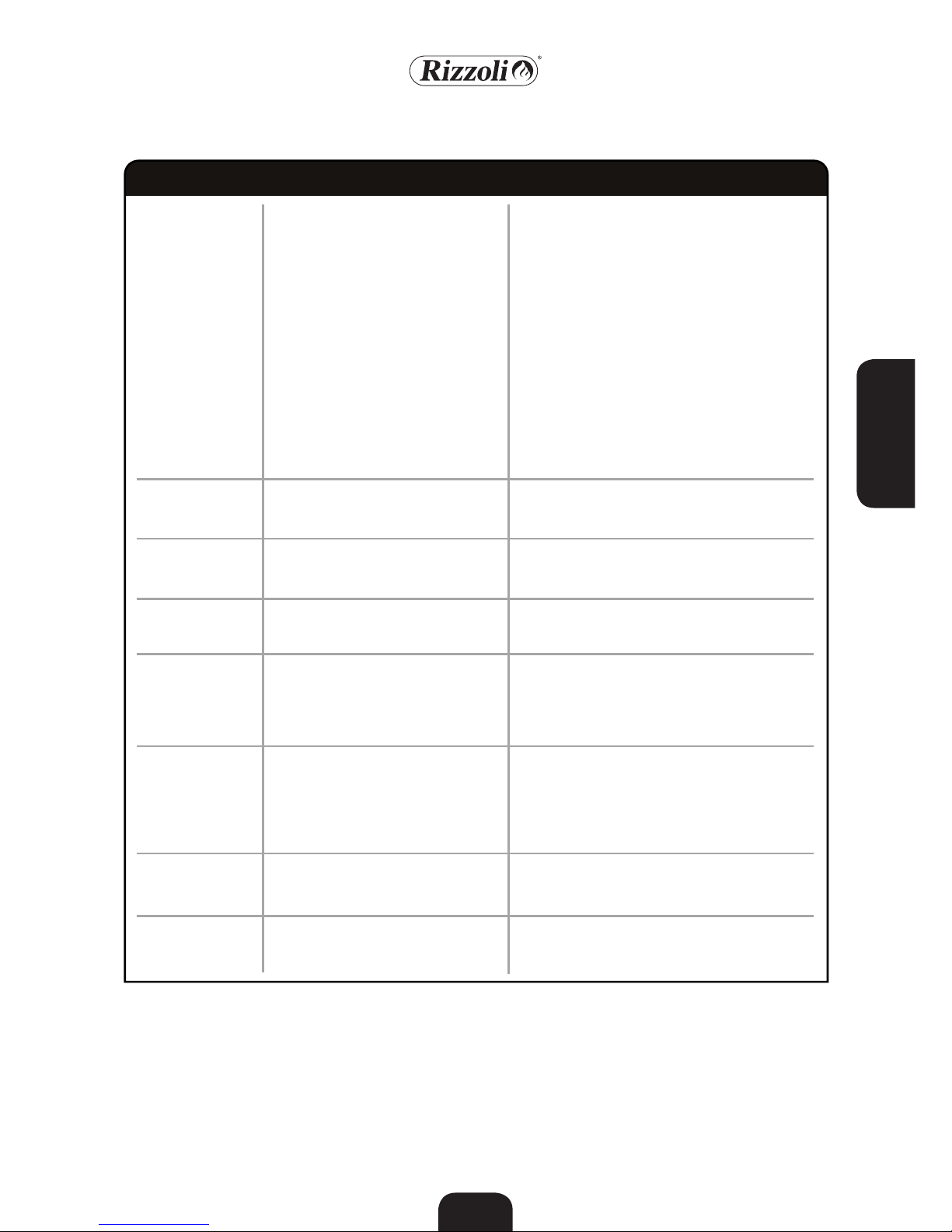
Bad working
Fire
Bad working
Overheating
Heating of oven is
weak
Condensation
Lighting failed
Rust
Irregular combustion.
Incomplete combustion.
Smoke comes out of the plate.
Smoke comes out of other parts of the
cooker.
The cooker and other parts near the
cooker take fire
Bad working due to bad weather
The cooker overheats. Oven’s thermometer is over 300 °C
The oven does not reach high temperatures
Condensation is created inside the
cooker; it may be caused by humidity
inside the walled parts. After the first
lightings it is normal the creation of
some condensation inside the new
cooker.
It is not possible to light the cooker
Presence of rust and deformations on
the plate
• Verify that the primary air regulator is open •
Verify that ash or other residuals do not obstruct
the grill • Verify that the grill is not inserted correctly (the flat part is up) • Verify that the place in
which the cooker is situated is well aired and that
aspiring hoods or other devices are not working
• Verify the correct dimensioning of the chimney
and of the entrance of the chimney • Verify that
the chimney is not obstructed and that it was cleaned recently • Verify that there are no losses in the
exhaust-pipe and in the conjunctions • Verify that
no other devices are connected to the flue • Verify
that the chimney suites the position in which it is
situated, in windy places you could have to install
an anti-wind chimney • Verify that the combustible is right, dry and of good quality • Verify that
the chimney does not go on under the wood fired
cooker
• Close all the air regulations of the cooker • Close
doors and windows of the room in which the
cooker is placed • Call the firemen
• Allow the flow of air in the room • Open a little
the ash door when you start the cooker • Eventually, use a windproof chimney-pot
• Close all the air regulations and if it is necessary
open the oven door
• Verify that oven door is well closed • Verify that
the starting key is closed • Set the air regulation to
the maximum opening position • Use good quality
wood, well dried and little patched • Verify that
combustion has strong flame
• Verify to use good and well seasoned wood •
Verify that the chimney has not something wrong
• Verify that the chimney is well isolated • Verify
that the chimney is not over dimensioned • Verify
that the cooker had the time to dry and to balance itself
• Air the place • Open the starting key • Use well
dried wood • Burn specified product existing in
commerce
• Do not clean the plate with water • Do the regular maintenance of the plate as describe • Contact
your dealer or the customer service
Problems Effects Possible solutions
5. WHAT TO DO IF…
Page 23
ENGLISH
84
Weight
Nominal power
Efficiency
Emissions CO (13% O
2
)
Chimney vacuum
Exhaust gas temperature (*)
Exhaust gas flow
Combustible consumption
Max. combustible quantity
Autonomy
Electric power
Tension
Frequency
160 kg
8 kW
80,2%
0,07%
10 Pa
191,4 °C
10 g/s
2,3 kg/h
3,0 kg
1 h
25 W
230 V
50 Hz
180 kg
8 kW
80,2%
0,07%
10 Pa
191,4 °C
10 g/s
2,3 kg/h
3,0 kg
1 h
25 W
230 V
50 Hz
210 kg
8 kW
80,2%
0,07%
10 Pa
191,4 °C
10 g/s
2,3 kg/h
3,0 kg
1 h
25 W
230 V
50 Hz
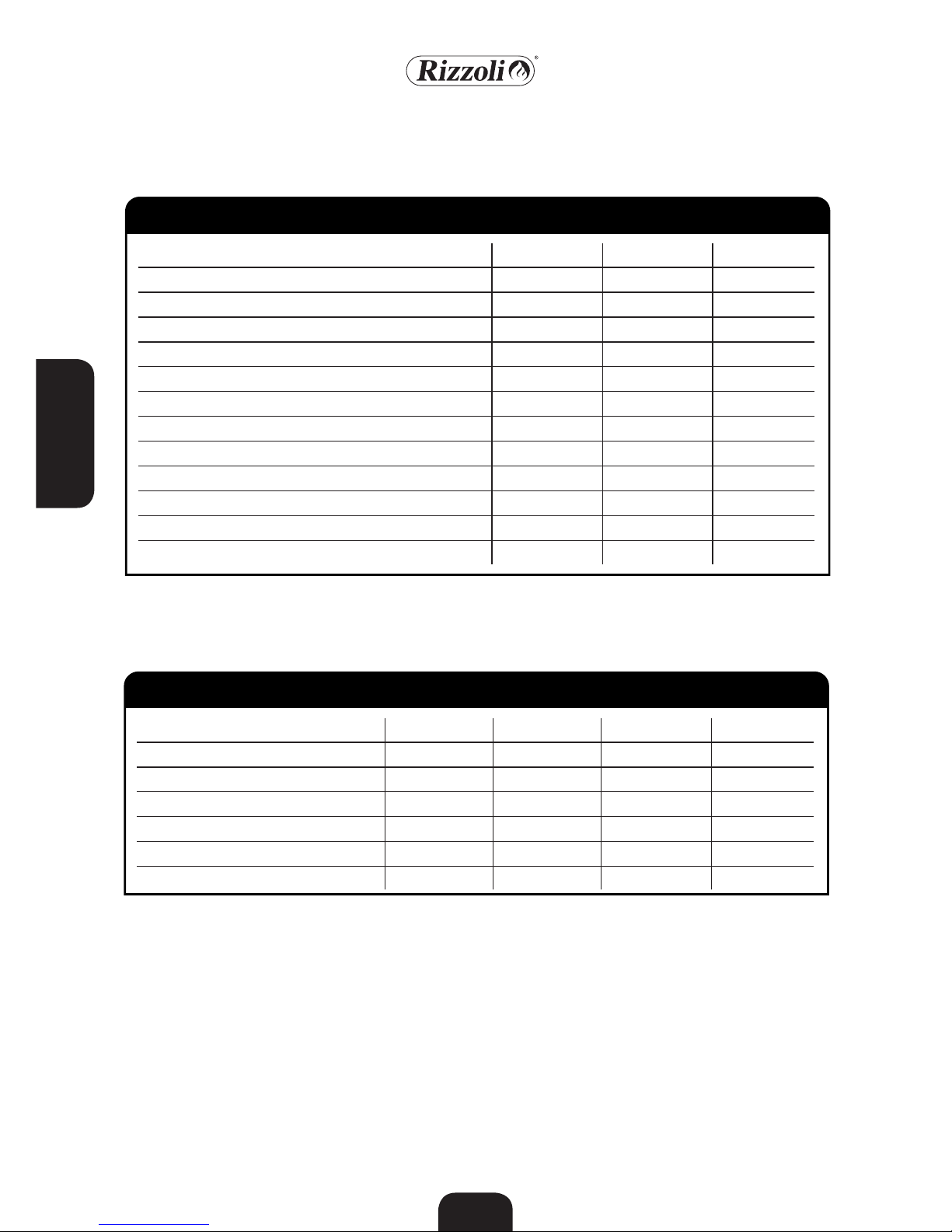
Model M 60 M 70 M 80
6.1 TECHNICAL DATA M RANGE
6. TECHNICAL DATA
(*) Average temperature at nominal power. It is possible to obtain higher instantaneous exhaust gas temperatures. It is
recommended to use always pipes with minimum specify T400.
(**) For devices with nominal power lower than 8 kW it is not requested the test with reduced power (Vereinbarung Art.
15a B-VG – 31.12.2012)
8 kW
80,2%
581 mg/MJ
85 mg/MJ
10,2 mg/MJ
9 mg/MJ
Yes
6.2 EMISSIONS ACCORDING TO 15A B-VG
Nominal power
Efficiency
Emissions CO (0% O
2
)
Emissions NOx (0% O
2
)
Dust Emissions (0% O
2
)
OGC Emissions (0% O
2
)
15a suitability (**)
8 kW
80,2%
581 mg/MJ
85 mg/MJ
10,2 mg/MJ
9 mg/MJ
Yes
8 kW
80,2%
581 mg/MJ
85 mg/MJ
10,2 mg/MJ
9 mg/MJ
Yes
-
> 72%
< 1100 mg/MJ
< 150 mg/MJ
< 35 mg/MJ
< 50 mg/MJ
-
Model M 60 M 70 M 80 15a B-VG
Page 24

ENGLISH
85
6.3 EMISSIONS ACCORDING TO BIMSCHV
Nominal power
Efficiency
Emissions CO (13% O
2
)
Dust emissions CO (13% O
2
)
BimSchV suitability
8 kW
80,2%
871 mg/m
3
15,3 mg/m
3
Yes
8 kW
80,2%
871 mg/m
3
15,3 mg/m
3
Yes
8 kW
80,2%
871 mg/m
3
15,3 mg/m
3
Yes
-
> 70%
< 1500 mg/m
3
< 40 mg/m
3
-
Model M 60 M 70 M 80 BImSchV
6.4 SAFETY DISTANCES M RANGE
M 60 7 cm 25 cm 80 cm 60 cm
M 70 7 cm 25 cm 80 cm 60 cm
M 80 7 cm 25 cm 80 cm 60 cm
Safety distances from inflammable or sensible to heat materials in absence of other isolating systems
Model Laterally Behind From On
Air regulation
Starting air
Starting key
6.5 REGULATIONS AT NOMINAL POWER
Model M 60 M 70 M 80
Half open
Closed
Closed
Half open
Closed
Closed
Half open
Closed
Closed
Page 25

ENGLISH
86
7. WARRANTY
Rizzoli warrants that the device has passed
all the quality controls and internal tests.
Rizzoli also warrants that the device is working, without imperfections due to building
or due to materials. This device is the result
of the pluridecennial experience of Rizzoli,
who warrants a perfectly made product.
Warranty lasts 2 years since the day of purchase. It is valid for the purchaser only, it is
not transferable.
To receive the warranty services the custom-
er must provide a valid fiscal document of
purchase (cash voucher, invoice etc.) and the
enclosed warranty card. Keep them with
care.
Rizzoli reserves, in its unquestionable judgement, to choose the the action that best fits
the problem object of warranty.
The imperfect replaced parts remain
property of Rizzoli. Rizzoli, in its unquestionable judgement, will decide if the warranty operations must be done in place or
in its own factory. For operations made at
home in the period of warranty, the customer must pay a fixed call fee in force. This
fee must not be paid if the hood has been
bought in the previous 3 months.
For reparations made in Rizzoli Customer
Service centres, transport charges are due.
Imperfections or defects in the materials
must be signalled within 8 days since the
customer receives the products and anyway
this implies only the obligation to replace
what provided, excluding any additional responsibility.
Possible operations made out of the warranty period or in the cases in which warranty is
not appliable, will be charged according to
the pricelist in force. In this case will be also
charged the price of the spare parts.
This warranty does not cover the following,
and the customer will be required to pay
repair charge, even for defects occurring
within the warranty period referred to
above:
• Any defect that occurs due to mishandling.
• Any defect that occurs due to operations
performed that are not mentioned in the
sections of these instructions.
• Damages due to the connection of the
hood to a wrong sized vent-hole pipe.
• Any defect that occurs due to the lack of
application of the national and local laws.
• Any defect that occurs due to not perfectly
made installations.
• Any defect that occurs due to repair, modification, cleaning, etc. performed by anyone other than Rizzoli authorized Customer Service centres.
• Consumer parts like bulbs, active carbon
filters, etc.
7.1 DECLARATION OF PERFECTLY MADE PRODUCT
7.2 GENERAL CLAUSES
7.3 WARRANTY MODALITIES
7.4 IMPERFECTIONS OR DEFECTS IN THE MATERIALS
7.6 OPERATIONS MADE OUT OF THE WARRANTY PERIOD
7.5 PARTS NOT INCLUDED IN WARRANTY
 Loading...