


Instruction Manual
RK-4500
KS5 & KS6
Automatic Hand Riveter.
Continuous Riveting Machine.
FOR
SALES, SERVICE OR TECH SUPPORT CALL: 1800-BUY-RIVET
OR
1-800-289-7483

ONTENTS
C
Safety Precautions Page 3
Specifications
Standard Rivets Page 5
Page 4
Types of Connecting Tape / Standard
Accessories
Preparing the tool for service Page 7-8
Maintenance Page 9-14
Installing and removing connecting tape Page 15-16
Troubleshooting
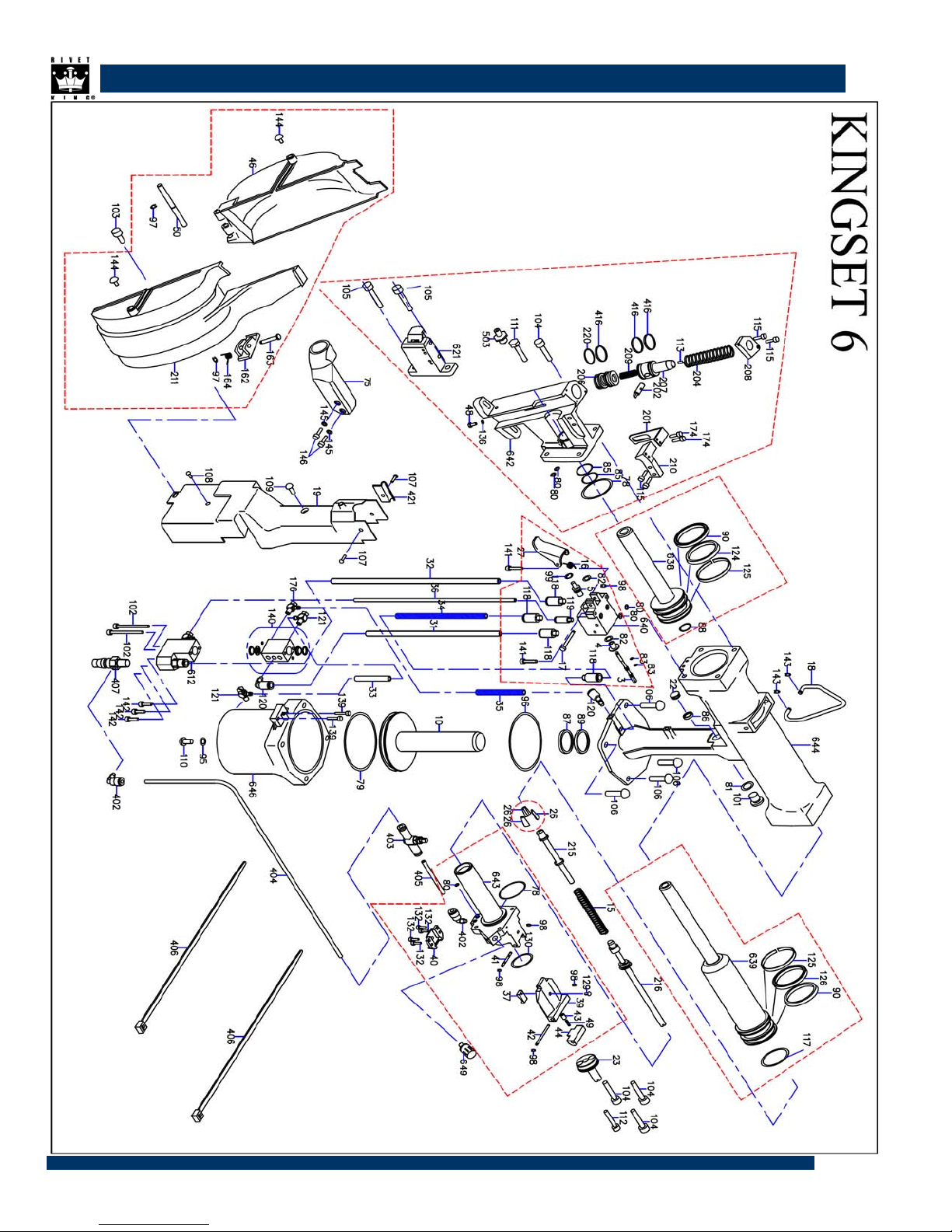
Assembly Drawings
Parts List Page 19-21
Schematic Page 21-23
MSDS Page 24-29
Warranty
Page 6
Page 17-18
Page 30
2

AFETY
S
DO NOT USE OUTSIDE DEISNG INTENT OR WITH EQUIPMENT THAT IS NOT RECOMMENDED BY THE MANUFACTURER.
ALWAYS DISCONNECT THE AIR SUPPLY BEFORE ATTEMPTING ANY MAINTENANCE OR ADJUSTMENT/FITTING OF NO SE EQUIPMENT
DO NOT OPERATE A TOOL THAT IS DIRECTED TOWARDS ANY PERSON(S) OR WITH THE NOSE PIECES OFF THE TOOL
ALL MODIFICATIONS CARRIED OUT ON THE TOOL WITHOUT EXPRESS WRITTEN CONSENT OF THE MANUFACTURER SHALL BE DONE SO
AT THE CUSTOMERS
’ SOLE RESPONSIBILITY
REFER TO THIS MANUAL BEFORE ATTEMPTING ANY MAINTENANCE OPERATION. DO NOT DISASSEMBLE THIS TOOL BEFORE RFERING TO
THIS MANUAL
.
AVOID EXCESSIVE CONTACT WITH HYDRAULIC OIL, AS SOON AS POSSIBLE WASH HANDS THOROUGHLY
DO NOT EXCEED 6 BAR / 90 PSI INLET PRESSURE, THE USE OF A PRESSURE REGULATOR IS HIGHLY RECOMMENDED
INSPECT THE TOOL USING PREVENTITIVE MAINTENANCE TECHNIQUES AT REUGULARLY SCHEDULED INTERVALS. INSPECT FOR DAMAGE
AND FUNCTION BY TRAINED A PERSONAL
DAMAGE
, CHIPPING, OR CRACKING.
. THE PLASTIC BODY MUST BE CHANGED WHERNEVER THERE IS EVIDANEC OF IMPACT
WEAR SAFETY GLASSES AND ADOPT FIRM FOOTING DURING OPERATION.
EXPLAIN HOW TO HANDLE THE MACHINE, AND MAKE SURE THE MANUAL HAS BEEN READ AND CLEARLY UNDERSTOOD.
DO NOT USE THE MACHINE IN AWKWARD POSITIONS.
BE AWARE OF YOUR SURROUNDINGS DURING OPERATION, DO NOT WORK NEAR DANGEROUS OBJECTS, AND DO NOT ALLOW NON-
OPERATING PERSONNEL TO COME NEAR.
DO NOT PUT THE FACE NEAR THE AIR EXHAUST DURING OPERATION, OIL OR MANDRELS MAY COME FLYING OUT OF THE EXHAUST,
CAUSING EYE INJURY
.
AVOID GETTING OIL AND GREASE ON THE SKIN, THIS MAY CAUSE INFLAMMATION OF THE SKIN, SO SHOULD BE THOROUGHLY WASHED
.
OFF
DO NOT USE THE MACHINE WHEN THE COVER PLATE IS OFF. THIS MAY RESULT IN TRAPPED FINGERS OR OTHER INJURY.
THESE SAFETY PRECAUTIONS ARE DESIGNED TO COVER ALL EVENTUALITIES FORESEEABLE BY THE MANUFACTURER, IN ANY OTHER
CIRCUMSTANCE
, THE USER IS URGED TO EXERCISE ALL DUE CAUTION.
3

SPECIFICATIONS
The specifications and information contained in this manual are applicable only to the tool with which it was
supplied. Industrial Rivet & Fastener Co reserve the right to make any changes without notice as part of Industrial
Rivet & Fastener Co policy of continuous improvement.
SPECIFICATIONS FOR RK-4500 RIVET TOOL
Operating Air Pressure 85-95 psi [5-6.6 BAR]
Recommended Air Pressure 90 PSI [6 BAR]
Size 14.1x11.9x5.7” [358X303X146mm]
Pull Force 1,300 lbf [5782 N]
Stroke .709 [18mm]
Cycle Time 0.9 seconds
Noise Level 85 dB(A)
Weight 5.08 lbs [2.3kg]
Vibration
Hydraulic Oil Mobil DTFE 24
Capacity KS5 = 1/8 & 5/32”
Mandrel Collection Capacity 1 Full Coil
2.5m/s2
KS6 = 3/16”
4

Standard Rivets
Material
Type of Rivet
Open
Shield
(N.B. This does not include articles with a breaking force of greater than 658 kgf)
Dimensions
A : Suitable size ----------------------- mandrel side tape hole size +0.1mm
Material
Rivet Body Mandrel
Aluminum Aluminum
Aluminum Steel
Aluminum Stainless Steel
Steel Steel
Stainless Steel Steel
Stainless Steel Stainless Steel
(Use the size of tape closest to the appropriate size)
Rivet Outer Diameter (mm) (in)
size 4 size 5 size 6
(φ3.2) (φ1/8) (φ4.0) (φ5/32) (φ4.8) (φ3/16)
○ ○ ○
○ ○ ○
○ ○ ○
○ ○ ○
○ ○
○ ○
×
×
B : size 4 rivet ------------------------------ 1/8 Inch
size 5 rivet ------------------------------ 5/32 Inch
size 6 rivet ------------------------------ 3/16 Inch
C : size 4 rivet ------------------------------ 1.06 In ~ 1.41 In
size 5 rivet ------------------------------ 1.10 In ~ 1.41 In
size 6 rivet ------------------------------ 1.14 In ~ 1.41 In
D : RK-4500KS5 / RK-4500KS5 ----------- Maximum 0.88 In
E : Maximum -------------------------------- 2.165 In
F : RK-4500KS5 ---------------------------- Maximum 0.32 In
RK-4500KS5 ---------------------------- Maximum 0.40 In
For other or special rivets, please consult Industrial Rivet & Fastener Co.
( N.B. 0.63 In when using LF tape )
A
C
E
D
B
F
5

TYPES OF CONNECTING TAPE
DANGER! IN ORDER TO AVOID DAMAGE TO THE RIVETER AND ACCIDENTS, USE ONLY THE RIVET KING CONNECTING TAPE.
TABLE SHOWING TYPES OF TAPE AND TAPE SELECTION OPEN TYPE AND SHIELD TYPE.
Type of Tpae
4A type .125 In .119 In .067 In
Rivet Body
Diameter
KS5
Connecting Tapes Reference Hole
Dimensions
Rivet Body Side Mandrel Side
TANDARD ACCESSORIES
S
(1) Jet Oiler ------------------------------------ 1 pcs (7) Single-ended Wrench (15mm) ------- 1 pcs
(2) Minus Screwdriver with tube ----------- 1 pcs (8) Single-ended Wrench (14mm) ------- 1 pcs
(3) Refilling Maintenance Bolt ------------- 1 pcs (9) Hexagonal Wrench (5mm) ------------ 1 pcs
(4) Pipe Spanner ------------------------------ 1 pcs (10) Hexagonal Wrench (2.5mm) ---------- 1 pcs
(5) Nosepiece - 5 (AHR5V2 only) ---------- 1 pcs (11) Training Nose Adaptor ------------------ 1 pcs
4B type .125 In .119 In .071 In
5C type .157 In .150 In .085 In
5D type .157 In .150 In .090 In
KS6
6E type .188 In .183 In .100 In
6F type .188 In .183 In .110 In
6M type .188 In .183 In .114 In
6H type (for LF) .188 In .183 In .100 In
6L type (for LF) .188 In .183 In .110 In
(6) Jaw Setting Jig --------------------------- 1 set (12) Air Hose Assembly ----------------------- 1 pcs
NOTE: AN OPTIONAL TRAINING NOSE ADAPTOR IS
SHIPPED WITH THE KINGSET™ TOOL (FIG. 2).
THE TRAINING NOSE ADAPTOR MAY BE INSTALLED
TO PREVENT ACCIDENTAL TOOL AND/OR APPLICATION
DAMAGE DUE TO THE CYCLING MOTION OF THE NOSE
PISTON UNTIL THE OPERATOR BECOMES FAMILIAR WITH
THE TOOL OPERATION.
PREPARING THE TOOL FOR SERVICE
6

IR SUPPLY
A
The rivet tool is powered by compressed air at an optimum pressure of 90 psi (6 BAR)
The use of a pressure regulator filter/lubricator unit within 3 meters of the tool is highly
recommended to extend the life of the tool.
Dirt and/or water in the air supply can seriously impact the performance and durability of
the tool; damage to the tool caused by contaminated air supply is not covered under
warranty
If the air pressure is too high, there is a danger of parts being damaged,
While if it is too low, riveting may not be possible.
UNPACKING AND INSPECTION
Unpack the tool making sure all components are present. Keep the box and do not damage it.
You may wish to use it to send the tool back to us for scheduled maintenance or repair.
Check for visible damage to the hydraulic cylinder. Mild abrasions are common in the painting
process, however, check for hairline cracks or broken parts which might have occurred during
shipping.
Fit the air hose (Valve Side) to the base of the tool. Do not over tighten.
Check the air pressure service and insure it is between 85-95 psi [5-6.6 BAR]. (adjust if necessary)
Connect the air hose to the air service line.
Test fire the tool without rivets listening to the tool to insure it properly cycles.
Check that the only visible moving part (take-up reel located at the back left side of the tool)
to insure it spins with each cycle.
Disconnect the air hose until ready for riveting.
7

NOSEPIECE – CHECK TO MAKE SURE IT IS THE CORRECT ONE
1
.
1
.
1
.
Measure the diameter of the rivet to be placed.
2
.
2
.
2
.
Insure the proper nose piece is provided with the tool. (See Rivet & Nose Piece
Selection, page13). If the proper nose piece is not provided with the tool, call the
sales department.
3
.
3
.
3
.
Hand tighten all nose piece connections. Do not over tighten.
4. Change the nosepiece to suit the size of rivet being used.
The nosepiece fitted is the one designated when ordering. The nosepiece should be changed
if a different size of rivet is used.
When changing the nosepiece, use the open-end wrench supplied.
Nosepiece
5. Areas of maintenance
When using the air-combination, remove the water from the air filter regularly,
adjust the regulator air pressure, and check the volume and flow of oil in the oiler.
Check for cracks in all parts, looseness of screws and fastenings and seeping or leaking of oil,
and ensure that the one touch cycle (automatic rivet setting system) is functioning properly.
5.
If too high an air pressure is used, the machine will break, possibly resulting in accident or injury.
As a safety device, the machine is equipped with an alarm device near the air inlet.
The outlet pressure is set at
must always be between
85-95 psi [5-6.6 BAR] when assembled. The air pressure used
85-95 psi [5-6.6 BAR].
( Restarting Method )
If the alarm valve comes into operation, restart according to the procedure described below.
(1) Disconnect the air.
(2)
Adjust the air supply pressure to an appropriate
level.
(3) Connect the air.
8

AINTENANCE
M
In order to maintain the tool in a safe working order it is important to carry out regular maintenance as
prescribed by the manufacturer. A thorough inspection replacement of all seals within the tool should be
carried out after 500,000 placings or annually, whichever is the sooner. Item numbers in parentheses
refer to assembly drawing part numbers
Daily Maintenance
Check for air leaks. Any damaged hoses should be replaced
Lubricate the tool by pouring a few drops of light lubricating oil into the air inlet on the tool
If there is no pressure regulator, bleed the airline to clear it of accumulated dirt or water before
connecting the air hose to the tool. If there is a filter, drain it.
Check for proper nose piece which is dependent on the size of the rivet.
Remove the nose piece from the front nose assembly and inspect for cracks, wear or other
damage. Replace if necessary.
Check that front nose assembly is fully tightened onto body
1.
Clean the 3-piece Jaw from the nosepiece side.
Using the air gun is dangerous, and protective glasses should always be worn.
Remove the nosepiece using the spanner set supplied, and remove any metal filings
from around the jaw using the air gun. Use a rag to prevent the metal filings from
flying around. Check the amount of dirt while doing this and, if necessary, remove the
jaw and clean it.
2. Using the spanner supplied, remove the nosepiece.
Attach a maintenance tube to the tip of the
Screwdrivers supplied, and remove the slide guide.
(Drawing 1)
9

3.
While holding the trigger, affix the nose piston
as far back as it will go, and remove the air plug.
(Drawing 2)
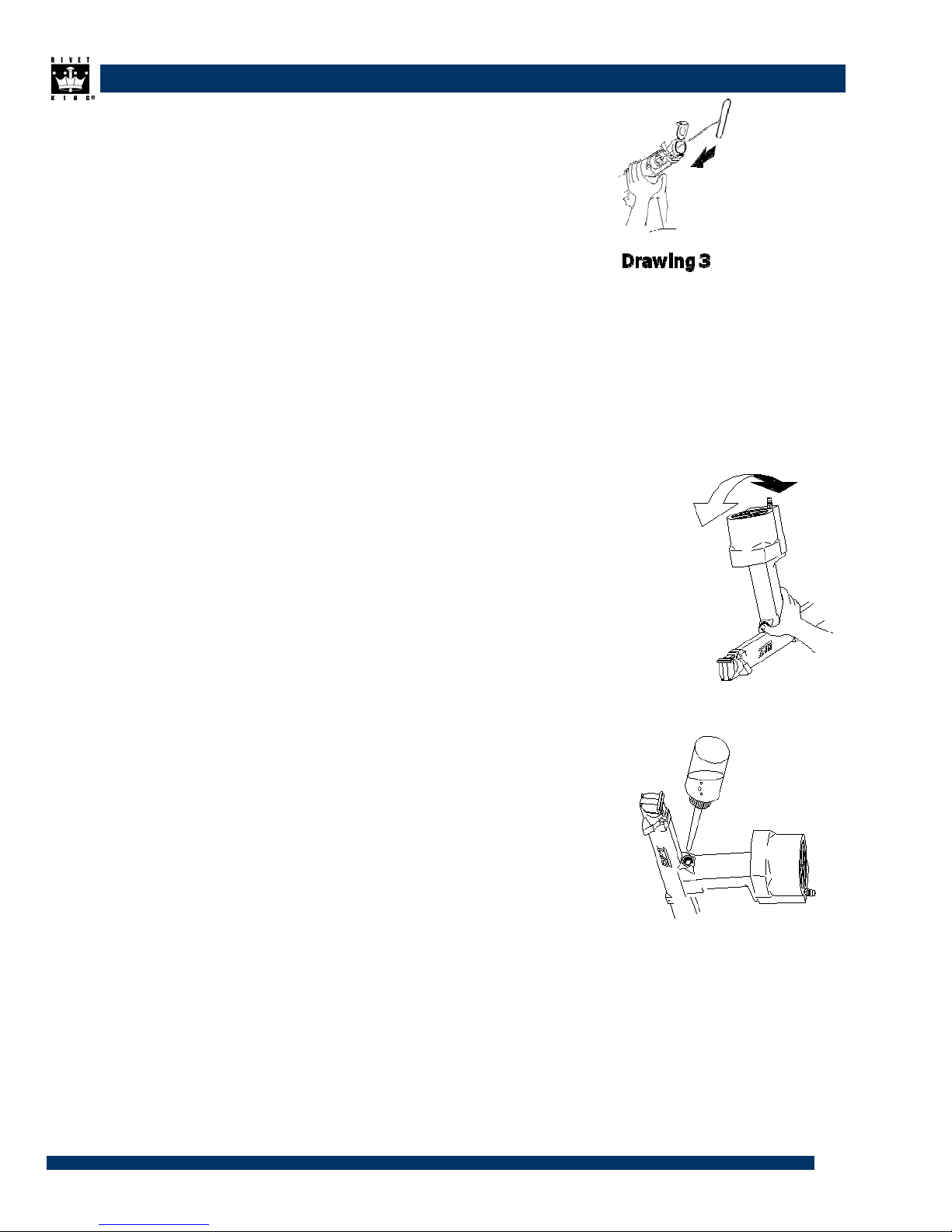
4. Using the pipe spanner and screwdriver supplied, remove (Drawing 3) the slide pipe.
(Drawing 4-D)
Use the pipe spanner by aligning with the jaw case piston at the back and affixing.
5. Hold the machine upside down, and take out the slide pipe (Drawing 4-D),
jaw pusher spring (Drawing 4-C), jaw pusher (Drawing 4-B) and jaw (Drawing 4-A).
If grease has caused the jaw to become stuck to the inside, push it out from the nose
piston side with the refilling maintenance bolt.
6. Clean the parts removed with kerosene or the equivalent. Use a wire brush to thoroughly
remove any metal filings from the teeth of the jaw. Any filings on the body of the jaw can
be removed with an air gun.
10

7. Insert 3 jaws into the tip of the tube on the
the outside of the jaw Setting Jig.
(Drawing 5, Drawing 6)
As shown in Drawing 6, apply an
over-the-counter Molybdenum grease.
(Note that applying grease to the jaw
teeth will cause the teeth to slip on the
rivets, and may make riveting impossible ).
8. Insert the jig, as shown in (Drawing 7).
Stop it about 5mm before it touches the end,
and press the knob on the inside of the tube.
(Drawing 8 )
Apply grease here
11
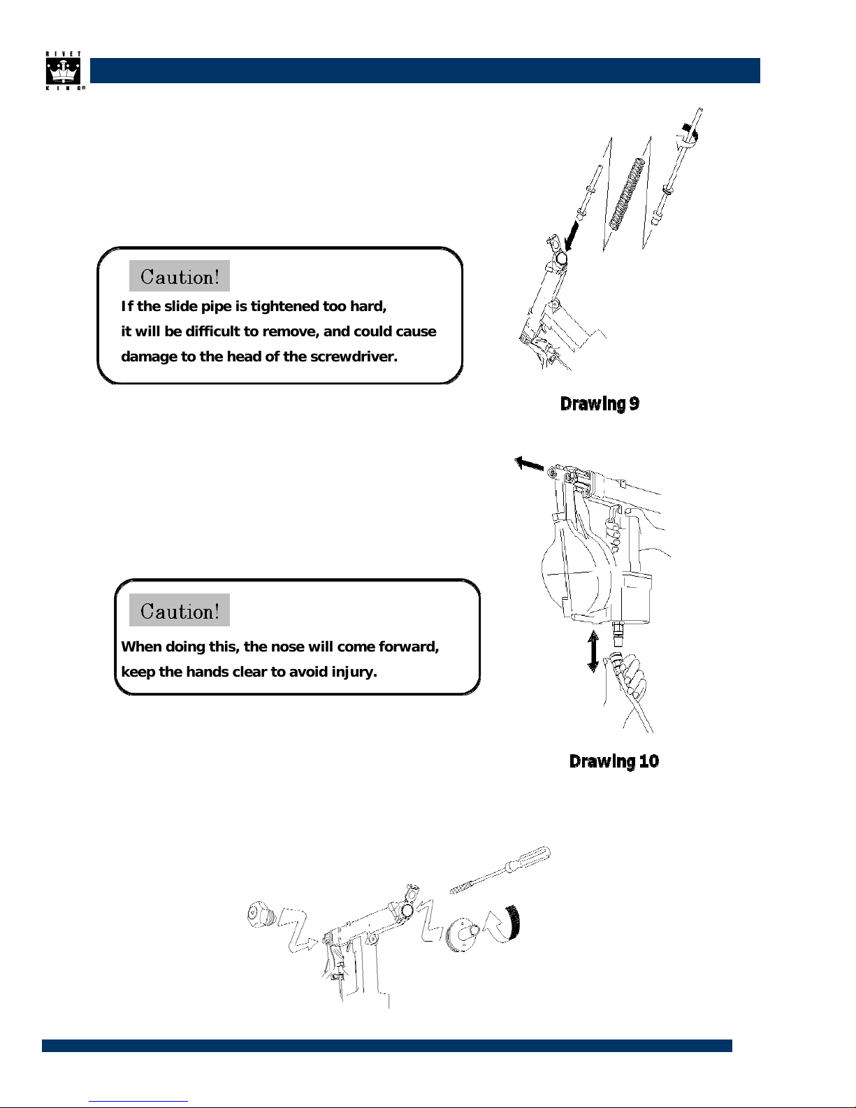
Insert the parts in the order shown in (Drawing 9),
9.
and use the screwdriver and pipe spanner supplied
to attach the slide pipe.
If the slide pipe is tightened too hard,
it will be difficult to remove, and could cause
damage to the head of the screwdriver.
10. Connect the air coupler, return the air cycle to its
starting point, and disconnect the air coupler.
(Drawing 10)
When doing this, the nose will come forward,
keep the hands clear to avoid injury.
11. Use the supplied screwdriver with tube attached to attach the slide guide inside the cap case.
(Drawing 11)
Use the open-end wench supplied (sizes 14mm and 15mm) to attach the nosepiece.
12

Air Removal (Bubbles) and Refilling Methods
Air release and refilling are needed in the following cases.
a.
Operating speed seems to
have slowed
b. After around 20,000 rivetings.
c.
A gap can be seen in the nose tip (Drawing 1-A)
when disconnecting the air coupler.
1. Remove any rivets still attached to the machine, as well as all broken off mandrels.
Wipe off any dirt that may be adhering to part (Drawing 1-A).
2. Stop the air supply. (disconnect the air coupler)
Always disconnect the air
3.
hose when releasing air or
refilling.
Use the hexagonal wrench (5mm) to remove the refilling
plug.
(Drawing 2)
13
4.
Cover the fuel inlet with a rag. (Drawing 3)
5. With the rag still in place, open the cap, and press hard on the
slide pipe with the refilling maintenance bolt. (Drawing 3)
* Check that the gap in Drawing 1-A has disappeared.
6. Cover the fuel inlet with the thumb, and turn the riveter
upside down to move the air in the hydraulic chamber into
the booster cylinder. (Drawing 4)
7. Bring the fuel inlet slowly back to the top again, and
replenish the oil to cover the amount of air bubbles
that appear. (Drawing 5)
8. Repeat steps 6 and 7 2 or 3 times until the air bubbles stop appearing,
then replenish until just short of overflowing and replace the refilling plug.
14

Installing the Connecting Tape Removing the Connecting Tape
1)
2)
3)
Push the magazine latch
towards the magazine
Push the magazine
1)
latch
towards the
magazine
and open it. and open it.
Roll up the connecting
tape containing the
rivets,
and put it in the
magazine.
Feed the tip of the tape
Still holding the trigger,
2)
pull the finished
tape
upwards.
After removing the
3)
tape,
under the plate spring, release the trigger.
4)
5)
and hook the first guide
hole on the back of the
tape on to the feeding
claw.
Close the magazine to
hold
4)
Turn off the air supply,
the connecting tape in and always throw away
place. the mandrels in the
holder.
Connect the air hose and
pull the trigger once.
A rivet will automatically
be fed into the nosepiece.
15

Removing the Connecting Tape
Use the speed controller to raise the vacuum
(1)
pressure until the rivet is held in place.
Affix with the Lock
(2)
nut.
Always disconnect the air hose when loading the connecting tape.
The following explanation should be read and clearly understood before starting operations.
AIR FITTING OPERATION The air fitting
supplied with the KingSet™ tools has an On/Off
flow valve built into it. To operate the v a lve, do
the following:
1. Push the female Quick-connect hose fitting
over the male fitting on the KingSet™ tool.
When fully connected you will see a blue
Indicator Ring (Fig. 1).
2. To turn on the air supply to the tool, slide the
Sleeve toward the blue Indicator Ring.
3. To lock the fitting so that the air does not
accidentally get shut off, twist the Collar and
Sleeve so that the Locking Arrows line up.
Figure 1: Tool Air Supply fitting.
16

TROUBLESHOOTING
RK-4500 Trouble Countermeasures
17

TROUBLESHOOTING
Symptom Cause Action
Nose piston does not
stop moving
backwards and
forwards.
The mandrels do not
break.
The nose piston
stops halfway back.
The nose piston is
stuck at the back
position.
The operating speed
has dropped.
The mandrel is
jammed.
Air was supplied when the trigger's
main axis was at the air passage
changeover point.
Air pressure is too low.
Unsuitable rivets (high breaking
strength) were used.
There is not enough oil. Carry out air release and refilling.
The jaw is worn or loaded. Clean or replace jaw.
The mandrel has gone too far inside
the Mandrel Collector.
The slide pipe or slide guide have come
off.
There is dirt between the nose piston
and jaw case.
Air has accumulated in the hydraulic
chamber.
Air release was insufficient, meaning
that a large amount of oil has come in.
The grease around the 3-part jaw has
dried, so the jaw has become stuck to
the jaw case.
Air pressure has dropped. Wait until the pressure inside the compressor is
Air has accumulated in the hydraulic
chamber.
The grease has dried on one or more
parts.
The nosepiece is the wrong size. Use a nosepiece which is compatible with the
The jaw pusher and slide pipe are the
wrong size.
With the air supply connected, pull the trigger for
3 seconds or more.
Adjust air pressure to 85-95 psi [5-6.6 BAR].
After resetting, remove the jaw and rivets.
After resetting, open the cap and remove the
mandrel.
Remove the slide guide and slide pipe.
Remove all mandrels from inside, then
reassemble.
*N.B. If even one is left, the tool will not restart.
Remove the nosepiece, and clean around the jaw
with an air blower.
*If the trigger is pulled, then the air supply is
stopped immediately, a gap will open between the
pistons, making cleaning easier.
Carry out air release and refilling.
Carry out air release and refilling as described in
step 5, and check that the gap in Drawing 1-A has
disappeared.
Clean the jaw, apply Moly grease to the back of
the jaw , then reposition the jaw.
back to normal.
Carry out air release and refilling.
Apply 1 or 2 drops of oil (MOBILE DTE) to the
base of the nose piston and coupler, and move 5
~ 10 times.
*Keep an oiler permanently on hand.
rivets.
Use a jaw pusher and slide pipe which are
compatible with the rivets.
Incompatible rivets are being used. Contact the dealer or maker.
The rivets are not
being held.
The rivets will not
load.
There is a noise in
the coupler area.
The filter is blocked. Exchange cotton ball in the filter.
The nosepiece is the wrong size. Use a nosepiece compatible with the rivets.
The rivets are not inserted properly in
the connecting tape.
The plate spring attachment has been
removed, causing faulty positioning.
The alarm device has been activated. Check the air pressure, and adjust to the
Find the problem and correct it. Do not use in the
event of damage likely to have an effect on the
operation of the tool.
Apply to us or the retailer for repairs.
appropriate level.
18

TROUBLESHOOTING
Parts No. Parts Name
RK4500-1
RK4500-2
RK4500-3
RK4500-4
RK4500-5
RK4500-6
RK4500-10
RK4500-12
RK4500-13
RK4500-14
RK4500-15
RK4500-16
RK4500-17
RK4500-18
RK4500-19
RK4500-20
RK4500-21
RK4500-22
RK4500-23
RK4500-24
RK4500-25
RK4500-27
RK4500-28
RK4500-29
RK4500-30
RK4500-31
RK4500-32
RK4500-33
RK4500-34
RK4500-35
RK4500-36
RK4500-37
RK4500-39
RK4500-40
RK4500-41
RK4500-42
RK4500-43
RK4500-44
RK4500-46
RK4500-48
RK4500-49
RK4500-50
RK4500-78
RK4500-79
Nose Piston
Jaw Case
Trigger Shaft
Trigger Cover
Trigger Shaft Sleeve
Jaw Case Piston
High Pressure Piston
Trigger Block
Ejector Nozzle
Diffuser
Jaw Pusher Spring
Trigger Spring
Trigger Pin
Tool Hanger - Horizontal
Grip Cover
Relief Valve Spring
Relief Valve
Pilot Piston - Trigger
Slide Guide
Centering Finger
Centering Shaft
Trigger
Diffuser Pin - MCS
Centering Spring
Alarm Valve Screw
Air Valve Supply Tube
Air Supply Tube
Air Chamber Supply Tube
Piston Retract Supply Tube
Return Supply Tube
Air Valve Shuttle Supply Tube
Mandrel Deflector
Cap - MCS
Latch Box
Cap Shaft - MCS
Latch Shaft - MCS
Latch Spring Receiver - MCS
Latch - MCS
Magazine Base
Indexer Exhaust Bolt
Latch Spring - MCS
Magazine Pin
O-ring S40
O-ring JASO3067
Q'ty
KS5 KS6 KS5 KS6
1 1 RK4500-80
1 1 RK4500-81
1 1 RK4500-82
1 1 RK4500-83
1 1 RK4500-85
1 1 RK4500-86
1 1 RK4500-87
1 1 RK4500-88
1 1 RK4500-89
1 1 RK4500-90
1 1 RK4500-91
1 1 RK4500-92
1 1 RK4500-93
1 1 RK4500-94
1 1 RK4500-95
1 1 RK4500-96
1 1 RK4500-97
1 1 RK4500-98
1 1 RK4500-99
2 2 RK4500-101
2 2 RK4500-102
1 1 RK4500-103
1 1 RK4500-104
2 2 RK4500-105
1 1 RK4500-106
1 1 RK4500-107
1 1 RK4500-108
1 1 RK4500-109
1 1 RK4500-110
1 1 RK4500-111
1 1 RK4500-112
1 1 RK4500-113
1 1 RK4500-114
1 1 RK4500-115
1 1 RK4500-116
1 1 RK4500-117
1 1 RK4500-118
1 1 RK4500-119
1 1 RK4500-120
1 1 RK4500-121
1 1 RK4500-122
1 1 RK4500-123
2 2 RK4500-124
1 1 RK4500-125
Parts No. Parts Name
O-ring S4
O-ring P10
O-ring P6
O-ring S2
O-ring P18
Mini Y-packing φ8
Mini Y-packing φ24
Penta Seal φ15
Penta Seal φ24
Piston Air Seal φ41.5
DU Bushing 2408
DU Bushing 1810
DU Bushing 1508
DU Bushing 0404
Gasket M5
O-Ring S71
SUS E-Ring E3
SUS E-Ring E2
Retaining Ring - Internal
Refilling Plug
Cap Bolt - SUS M3x35
Cap Bolt - SUS M5x16
Cap Bolt - SUS M5x20
Torx Head Cap Bolt - SUS M5x25
Button Head Cap Bolt - SUS M6x16
Machince Screw - SUS M3x8
Tapping Screw - SUS M3x5
Machince Screw - SUS M4x8
Machince Screw - SUS M5x8
Hexagonal Bolt - SUS M5 x 20
Cap Bolt - SUS M4x20
Set Screw - SUS M4x8, Cone Point
Set Screw - SUS M3x6, Flat Point
Cap Bolt - SUS M3x8
O-ring S6
O-ring JASO2030
Push to Connect Male 6mm x M6
Push to Connect Male 4mm x M5
Push to Connect Elbow 6mm x M5
360 Degree Barb Elbow 6mm x M5
360 Degree Barb Elbow 4mm x M5
Push to Connect Male 6mm x 1/8
Nose Piston Hydraulic Seal
Wear Ring φ41.5
Q'ty
5 5
1 1
2 2
3 3
2 2
1 1
1 1
1 1
1 1
2 2
1 1
1 1
1 1
4 4
1 1
1 1
2 2
5 5
1 1
1 1
2 2
1 1
4 4
2 2
4 4
2 2
1 1
1 1
1 1
1 1
1 1
1 1
2 2
2 4
1 1
1 1
4 4
1 1
2 2
2 2
1 1
1 1
1 1
2 2
19

Common Parts
Parts No. Parts Name
RK4500-126
RK4500-127
RK4500-128
RK4500-129
RK4500-130
RK4500-132
RK4500-133
RK4500-136
RK4500-138
RK4500-139
RK4500-140
RK4500-141
RK4500-142
RK4500-143
RK4500-144
RK4500-145
RK4500-146
RK4500-151
RK4500-162
Exclusive Parts
Parts No. Parts Name
RK4500-11
RK4500-45
RK4500-47
RK4500-51
RK4500-52
Jaw Case Piston Hydraulic Seal
Steel Ball - 4mm
Set Screw - SUS M5x5, Flat Point
Machince Screw - SUS M3x5
O-ring P28
Cap Bolt - SUS M3x8
Steel Ball - 3mm
Indexer Exhaust Gasket M3
Steel Ball - 2mm
Cap Bolt - SUS M2.5x12
Air Operated Valve
Cap Bolt - SUS M3x14
Cap Bolt - SUS M3x8
SUS E-ring E3
Magazine Foot
Washer M3
Cap Bolt - SUS M3x12
Mandrel Collector Housing
Magazine Latch
Valve Block - 5
Magazine Cover - 5
Cover Plate
Centering Finger Base - 5
Plate Spring - 5
Q'ty
KS5 KS6 KS5 KS6
1 1 RK4500-163
2 2 RK4500-164
1 1 RK4500-174
1 1 RK4500-176
1 1 RK4500-178
4 4 RK4500-180
11 12
1 1 RK4500-183
1 1 RK4500-184
2 2 RK4500-185
1 1 RK4500-402
2 2 RK4500-403
3 3 RK4500-404
2 2 RK4500-405
2 2 RK4500-406
2 2 RK4500-407
2 2 RK4500-409
1 1 RK4500-410
1 1 RK4500-421
Q'ty
KS5 KS6 KS5 KS6
1 1 -
1
-
1
-
1
-
Parts No. Parts Name
Magazine Latch Pin
Magazine Latch Spring
Torx Head Bolt - SUS M3x8
360 Deg Barb Elbow 6mm x
M5
Casing
RK4500-182
Parts No. Parts Name
RK4500-417
RK4500-26
RK4500-201
RK4500-202
RK4500-203
Booster Cylinder
Filter Holder
Filter Case
Cotton Ball
O-ring 1A-SS12
Vacuum Tube Elbow Fitting
Vacuum Adjuster
Vacuum Tube - Long
Vacuum Tube - Short
Cable Tie
Coupler Plug - Male
Inline Hook
Retaining Ring - E-Ring
Vacuum Tube Support
Unit Jaw - 5
3-part Jaw - 6
Plate Spring - 6
Pawl - 6
Indexer Housing - 6
Q'ty
1 1
1 1
2 2
1 1
1 1
1 1
1 1
1 1
2 2
1 1
2 2
1 1
1 1
1 1
2 2
1 1
1 1
1 1
1 1
Q'ty
1 -
- 3
1
-
1
-
1
-
RK4500-53
RK4500-54
RK4500-55
RK4500-56
RK4500-57
RK4500-58
RK4500-59
RK4500-60
RK4500-61
RK4500-62
RK4500-134
RK4500-135
RK4500-137
RK4500-414
Plate Spring Support - 5
Indexer Piston A - 5
Indexer Piston B - 5
Pawl - 5
Indexer Cap - 5
Indexer Spring - 5
Indexer Buffer Spring - 5
Indexer Housing - 5
Jaw Pusher - 5
Slide Pipe - 5
Button Head Cap Bolt - SUS M3x6
O-ring P20
Cap Bolt - SUS M2.5x10
Wear Ring 24mm
1
-
1
-
1
-
1
-
1
-
2
-
1
-
1
-
1
-
1
-
2
-
2 - RK4500-220
4 - RK4500-416
1
-
RK4500-204
RK4500-205
RK4500-206
RK4500-207
RK4500-208
RK4500-209
RK4500-210
RK4500-211
RK4500-214
RK4500-215
RK4500-216
Indexer Spring - 6
Centering Finger Base - 6
Indexer Piston A - 6
Indexer Piston B - 6
Indexer Cap - 6
Indexer Buffer Spring - 6
Plate Spring Support - 6
Magazine Cover - 6
Valve Block - 6
Jaw Pusher - 6
Slide Pipe - 6
O-ring P16
Wear Ring φ20
-
-
-
-
-
-
-
-
-
-
-
- 1
- 3
1
1
1
1
1
1
1
1
1
1
1
20

Assembly Parts
Parts No. Parts Name
RK4500-603
RK4500-604
RK4500-605
RK4500-607
RK4500-608
RK4500-609
RK4500-610
RK4500-611
RK4500-612
RK4500-613
RK4500-614
RK4500-616
RK4500-617
RK4500-618
RK4500-619
Nose Assembly - 5
Alarm Valve Assembly - 5
Cap Assembly
Jaw Case Piston Assembly
Trigger Shaft Assembly
Trigger Valve Assembly
Casing Assembly
Nose Piston Assembly
Alarm Valve Assembly - 6
Nose Assembly - 6
Mandrel Collector Housing
Assmbly
Magazine Assembly - 5
Magazine Assembly - 6
3-piece Jaw Set - 5
3-piece Jaw Set - 6
Q'ty
KS5 KS5 KS5 KS6
1
1
1 1 RK4500-622
1 1 RK4500-623
1 1 RK4500-638
1 1 RK4500-639
1 1 RK4500-640
1 1 RK4500-641
- 1
-
1 1 RK4500-644
1
-
1
-
-
-
1
-
1
-
1
Parts No. Parts Name
RK4500-620
RK4500-621
RK4500-642
RK4500-643
RK4500-646
RK4500-649
RK4500-651
Centering Assembly - 5
Centering Assembly - 6
Booster Cylinder Assembly
Jaw Setting Jig
Nose Piston Sub Assembly
Jaw Case Piston Sub Assembly
Trigger Valve Sub Assmbly
Nose Sub Assembly - 5
Nose Sub Assembly - 6
Mandrel Collector Housing Sub
Assembly
Casing Sub Assembly
Booster Cylinder Sub Assmbly
Filter Assembly
Centering Finger Sub Assembly
Q'ty
1
-
1 1
1 1
1 1
1 1
1 1
1
- 1
1 1
1 1
1 1
1 1
2 2
-
1
-
Nosepieces
Parts No. Parts Name
RK4500-500
RK4500-501
RK4500-502
RK4500-503
Accessories
Parts No. Parts Name
RK4500-67
RK4500-68
RK4500-69
RK4500-70
RK4500-71
RK4500-72
RK4500-73
Nosepiece - 4 - FINE Acc
Nosepiece - 4
Nosepiece - 5
Nosepiece - 6
Jaw Hold Tube
Jaw Pushing Tube
Jaw Pushing Knob
Pipe Spanner
Refuelling Maintenance Bolt
Single-ended Wrench
(15mm)
Single-ended Wrench
(14mm)
Q'ty
KS5 KS6 KS5 KS6
-
1
1
-
KS5 KS6 KS5 KS6
1 1 RK4500-74
1 1 RK4500-75
1 1 RK4500-153
1 1 RK4500-154
1 1 RK4500-155
1 1 RK4500-636
1 1
-
-
1 RK4500-529
Q'ty
Parts No. Parts Name
RK4500-525
RK4500-527
RK4500-528
Parts No. Parts Name
RK4500-998
RK4500-999
Nosepiece - 4 - FINE/FLAT Acc
Nosepiece - 4 - FLAT Acc
Nosepiece - 5 - FLAT Acc
Nosepiece - 6 - FLAT
Minus Screw Driver with Tube
Training Nose Adaptor
Hexagonal Wrench (5mm)
Hexagonal Wrench (2.5mm)
Jet Oiler
Air Hose Assembly
Spindle Oil – 1 Quart
Moly Grease – 2.5 oz
Q'ty
-
-
-
-
Acc
Q'ty
1 1
1 1
1 1
1 1
1 1
1 1
1 1
1 1
21

Assemblies/Kits
Kit# 603 Part# RK4500-603-KS5 Nose Ass’y (Cut version)
KCK
Part#
48 RK4500-048-KS Indexer Exhaust Bolt 1
52 RK4500-052-KS5 Plate Spring - 5 1
53 RK4500-053-KS5 Plate Spring Support - 5 1
54 RK4500-054-KS5 Indexer Piston A - 5 1
55 RK4500-055-KS5 Indexer Piston B - 5 1
56 RK4500-056-KS5 Pawl - 5 1
57 RK4500-057-KS5 Indexer Cap - 5 1
58 RK4500-058-KS5 Indexer Spring - 5 2
59 RK4500-059-KS5 Indexer Buffer Spring - 5 1
78 RK4500-078-KS O-ring S40 1
80 RK4500-080-KS O-ring S4 2
85 RK4500-085-KS O-ring P18 2
113 RK4500-113-KS Socket Set Screw - SUS M4x8, Cone Point 1
115 RK4500-115-KS Socket Head Cap Bolt - SUS M3x8 2
135 RK4500-135-KS5 O-ring P20 2
136 RK4500-136-KS Indexer Exhaust Gasket M3 1
137 RK4500-137-KS5 Socket Head Cap Bolt - SUS M2.5x10 4
174 RK4500-174-KS Torx Head Cap Bolt - SUS M3x8 2
414 RK4500-414-KS5 Wear Ring φ24 1
641 RK4500-641-KS5 Nose Sub Assembly - 5 1
IRF Part# Part Name Q'ty
Kit# 604 Part# RK4500-604-KS5 Alarm Valve Ass’y
KCK
Part#
11 RK4500-011-KS5 Valve Block - 5 1
20 RK4500-020-KS Relief Valve Spring 1
21 RK4500-021-KS Relief Valve 1
30 RK4500-030-KS Alarm Valve Screw 1
83 RK4500-083-KS O-ring S2 1
122 RK4500-122-KS 360 Degree Barb Elbow 4mm x M5 1
123 RK4500-123-KS Push to Connect Male 6mm x 1/8 1
IRF Part# Part Name Q'ty
Kit# 605 Part# RK4500-605-KS5 Cap Ass’y
KCK
Part#
37 RK4500-037-KS Mandrel Deflector 1
39 RK4500-039-KS Cap - MCS 1
42 RK4500-042-KS Latch Shaft - MCS 1
43 RK4500-043-KS Latch Spring Receiver - MCS 1
44 RK4500-044-KS Latch - MCS 1
49 RK4500-049-KS Latch Spring - MCS 1
98 RK4500-098-KS SUS E-Ring E2 2
129 RK4500-129-KS Cross-recessed Pan-head Machince Screw - SUS M3x5 1
Kit# 607 Part# RK4500-607-KS5 Jaw Case Pison Ass’y
KCK
Part#
90 RK4500-090-KS Piston Air Seal φ41.5 1
117 RK4500-117-KS O-ring JASO2030 1
125 RK4500-125-KS Wear Ring φ41.5 1
126 RK4500-126-KS Jaw Case Piston Hydraulic Seal 1
639 RK4500-639-KS Jaw Case Piston Sub Assembly 1
IRF Part# Part Name Q'ty
IRF Part# Part Name Q'ty
22

Assemblies/Kits
continued
Kit# 608 Part# RK4500-608-KS5 Trigger Shaft Ass’y
KCK
Part#
3 RK4500-003-KS Trigger Shaft 1
83 RK4500-083-KS O-ring S2 2
Kit# 609 Part# RK4500-609-KS5 Trigger Valve Ass’y
KCK
Part#
4 RK4500-004-KS Trigger Cover 1
5 RK4500-005-KS Trigger Shaft Sleeve 1
16 RK4500-016-KS Trigger Spring 1
17 RK4500-017-KS Trigger Pin 1
27 RK4500-027-KS Trigger 1
80 RK4500-080-KS O-ring S4 2
82 RK4500-082-KS O-ring P6 2
98 RK4500-098-KS SUS E-Ring E2 1
99 RK4500-099-KS Retaining Ring - Internal 1
118 RK4500-118-KS Push to Connect Male 6mm x M6 3
119 RK4500-119-KS Push to Connect Male 4mm x M5 1
608 RK4500-608-KS Trigger Shaft Assembly 1
640 RK4500-640-KS Trigger Valve Sub Assmbly 1
Kit# 610 Part# RK4500-610-KS5 Casing Ass’y
KCK
Part#
87 RK4500-087-KS Mini Y-packing φ24 1
89 RK4500-089-KS Penta Seal φ24 1
96 RK4500-096-KS O-Ring S71 1
644 RK4500-644-KS Casing Sub Assembly 1
Kit# 611 Part# RK4500-611-KS5 Nose Piston Ass’y
KCK
Part#
88 RK4500-088-KS Penta Seal φ15 1
90 RK4500-090-KS Piston Air Seal φ41.5 1
124 RK4500-124-KS Nose Piston Hydraulic Seal 1
125 RK4500-125-KS Wear Ring φ41.5 1
638 RK4500-638-KS Nose Piston Sub Assembly 1
Kit# 612 Part# RK4500-612-KS5 Alarm Valve Ass’y
KCK
Part#
20 RK4500-020-KS Relief Valve Spring 1
21 RK4500-021-KS Relief Valve 1
30 RK4500-030-KS Alarm Valve Screw 1
83 RK4500-083-KS O-ring S2 1
122 RK4500-122-KS 360 Degree Barb Elbow 4mm x M5 1
123 RK4500-123-KS Push to Connect Male 6mm x 1/8 1
214 RK4500-214-KS6 Valve Block - 6 1
IRF Part# Part Name Q'ty
IRF Part# Part Name Q'ty
IRF Part# Part Name Q'ty
IRF Part# Part Name Q'ty
IRF Part# Part Name Q'ty
23

Assemblies/Kits
continued
Kit# 613 Part# RK4500-613-KS5 Nose Ass’y KS-6
KCK
Part#
48 RK4500-048-KS Indexer Exhaust Bolt 1
78 RK4500-078-KS O-ring S40 1
80 RK4500-080-KS O-ring S4 2
85 RK4500-085-KS O-ring P18 2
113 RK4500-113-KS Socket Set Screw - SUS M4x8, Cone Point 1
115 RK4500-115-KS Socket Head Cap Bolt - SUS M3x8 4
136 RK4500-136-KS Indexer Exhaust Gasket M3 1
174 RK4500-174-KS Torx Head Cap Bolt - SUS M3x8 2
201 RK4500-201-KS6 Plate Spring - 6 1
202 RK4500-202-KS6 Pawl - 6 1
204 RK4500-204-KS6 Indexer Spring - 6 1
206 RK4500-206-KS6 Indexer Piston A - 6 1
207 RK4500-207-KS6 Indexer Piston B - 6 1
208 RK4500-208-KS6 Indexer Cap - 6 1
209 RK4500-209-KS6 Indexer Buffer Spring - 6 1
210 RK4500-210-KS6 Plate Spring Support - 6 1
220 RK4500-220-KS6 O-ring P16 1
416 RK4500-416-KS6 Wear Ring φ20 3
642 RK4500-642-KS6 Nose Sub Assembly - 6 1
IRF Part# Part Name Q'ty
Kit# 614 Part# RK4500-614-KS5 Mandrel Collector Housing Ass’y
KCK
Part#
40 RK4500-040-KS Latch Box 1
41 RK4500-041-KS Cap Shaft - MCS 1
78 RK4500-078-KS O-ring S40 1
80 RK4500-080-KS O-ring S4 1
98 RK4500-098-KS SUS E-Ring E2 2
130 RK4500-130-KS O-ring P28 1
132 RK4500-132-KS Socket Head Cap Bolt - SUS M3x8 4
402 RK4500-402-KS Vacuum Tube Elbow Fitting 1
409 RK4500-409-KS Inline Hook 1
410 RK4500-410-KS Retaining Ring - E-Ring 1
605 RK4500-605-KS Cap Assembly 1
643 RK4500-643-KS Mandrel Collector Housing Sub Assembly 1
IRF Part# Part Name Q'ty
Kit# 616 Part# RK4500-616-KS5 Magazine Ass’y – KS5
KCK
Part#
45 RK4500-045-KS5 Magazine Cover - 5 1
46 RK4500-046-KS Magazine Base 1
50 RK4500-050-KS Magazine Pin 1
97 RK4500-097-KS SUS E-Ring E3 2
144 RK4500-144-KS Magazine Foot 2
162 RK4500-162-KS Magazine Latch 1
163 RK4500-163-KS Magazine Latch Pin 1
164 RK4500-164-KS Magazine Latch Spring 1
IRF Part# Part Name Q'ty
Kit# 617 Part# RK4500-617-KS6 Magazine Ass’y – KS6
KCK
Part#
46 RK4500-046-KS Magazine Base 1
50 RK4500-050-KS Magazine Pin 1
97 RK4500-097-KS SUS E-Ring E3 2
144 RK4500-144-KS Magazine Foot 2
162 RK4500-162-KS Magazine Latch 1
163 RK4500-163-KS Magazine Latch Pin 1
164 RK4500-164-KS Magazine Latch Spring 1
211 RK4500-211-KS6 Magazine Cover - 6 1
IRF Part# Part Name Q'ty
24

Assemblies/Kits
continued
Kit# 618 Part# RK4500-618-KS5 3 Piece Jaw – KS5
KCK
Part#
417 RK4500-417-KS5 Unit Jaw-5 1
IRF Part# Part Name Q'ty
Kit# 619 Part# RK4500-619-KS6 3 Piece Jaw – KS6
KCK
Part#
26 RK4500-026-KS6 3-part Jaw 6 3
IRF Part# Part Name Q'ty
Kit# 620 Part# RK4500-620-KS5 Centering Ass’y – KS5
KCK
Part#
25 RK4500-025-KS Centering Shaft 2
29 RK4500-029-KS Centering Spring 2
47 RK4500-047-KS5 Cover Plate 1
51 RK4500-051-KS5 Centering Finger Base - 5 1
114 RK4500-114-KS Socket Set Screw - SUS M3x6, Flat Point 2
134 RK4500-134-KS Button Head Cap Bolt - SUS M3x6 2
651 RK4500-651-KS Centering Finger Sub Assembly 2
IRF Part# Part Name Q'ty
Kit# 621 Part# RK4500-621-KS6 Centering Ass’y – KS6
KCK
Part#
25 RK4500-025-KS Centering Shaft 2
29 RK4500-029-KS Centering Spring 2
114 RK4500-114-KS Socket Set Screw - SUS M3x6, Flat Point 2
205 RK4500-205-KS6 Centering Finger Base - 6 1
651 RK4500-651-KS Centering Finger Sub Assembly 2
IRF Part# Part Name Q'ty
Kit# 622 Part# RK4500-622-KS Booster Cylinder Ass’y
KCK
Part#
95 RK4500-095-KS Gasket M5 1
110 RK4500-110-KS Cross-recessed Pan-head Machine Screw - SUS M5x8 1
646 RK4500-646-KS Booster Cylinder Sub Assembly 1
IRF Part# Part Name Q'ty
Kit# 623 Part# RK4500-623-KS Jaw Setting Jig
KCK
Part#
67 RK4500-067-KS Jaw Hold Tube 1
68 RK4500-068-KS Jaw Pushing Tube 1
69 RK4500-069-KS Jaw Pushing Knob 1
IRF Part# Part Name Q'ty
Kit# 638 Part# RK4500-638-KS Nose Piston Sub Ass’y
KCK
Part#
1 RK4500-001-KS Nose Piston 1
93 RK4500-093-KS DU Bushing 1508 1
IRF Part# Part Name Q'ty
Kit# 639 Part# RK4500-639-KS Jaw Case Piston Sub Ass’y
KCK
Part#
2 RK4500-002-KS Jaw Case 1
6 RK4500-006-KS Jaw Case Piston 1
IRF Part# Part Name Q'ty
25

Assemblies/Kits
continued
Kit# 640 Part# RK4500-640-KS Trigger Valve Ass’y
KCK
Part#
12 RK4500-012-KS Trigger Block 1
127 RK4500-127-KS Steel Ball - 4mm 1
133 RK4500-133-KS Steel Ball - 3mm 3
IRF Part# Part Name Q'ty
Kit# 641 Part# RK4500-641-KS5 Nose Sub Ass’y – KS5
KCK
Part#
60 RK4500-060-KS5 Indexer Housing - 5 (Cut Ver.) 1
92 RK4500-092-KS DU Bushing 1810 1
133 RK4500-133-KS Steel Ball - 3mm 5
138 RK4500-138-KS Steel Ball - 2mm 1
IRF Part# Part Name Q'ty
Kit# 642 Part# RK4500-642-KS6 Nose Sub Ass’y KS6
KCK
Part#
92 RK4500-092-KS DU Bushing 1810 1
133 RK4500-133-KS Steel Ball - 3mm 6
138 RK4500-138-KS Steel Ball - 2mm 1
203 RK4500-203-KS6 Indexer Housing – 6 1
IRF Part# Part Name Q'ty
Kit# 643 Part# RK4500-643-KS Mandrel Collector Housing Sub Ass’y
KCK
Part#
13 RK4500-013-KS Ejector Nozzle 1
14 RK4500-014-KS Diffuser 1
28 RK4500-028-KS Diffuser Pin – MCS 1
116 RK4500-116-KS O-ring S6 1
133 RK4500-133-KS Steel Ball - 3mm 2
151 RK4500-151-KS Mandrel Collector Housing 1
IRF Part# Part Name Q'ty
Kit# 644 Part# RK4500-644-KS Casing Sub Ass’y
KCK
Part#
91 RK4500-091-KS DU Bushing 2408 1
127 RK4500-127-KS Steel Ball - 4mm 1
128 RK4500-128-KS Socket Set Screw - SUS M5x5, Flat Point 1
178 RK4500-178-KS Casing 1
IRF Part# Part Name Q'ty
Kit# 646 Part# RK4500-646-KS Booster Cylinder Sub Ass’y
KCK
Part#
133 RK4500-133-KS Steel Ball - 3mm 1
180 RK4500-180-KS Booster Cylinder 1
IRF Part# Part Name Q'ty
Kit# 649 Part# RK4500-649-KS Filter Ass’y
KCK
Part#
182 RK4500-182-KS Filter Holder 1
183 RK4500-183-KS Filter Case 1
184 RK4500-184-KS Cotton Ball 2
185 RK4500-185-KS O-ring 1A-SS12 1
IRF Part# Part Name Q'ty
Kit# 651 Part# RK4500-651-KS Centering Finger Sub Ass’y
KCK
Part#
24 RK4500-024-KS Centering Finger 1
94 RK4500-094-KS DU Bushing 0404 2
IRF Part# Part Name Q'ty
26

27
28

MSDS
Lubricant Details
MOLY GREASE
(MSC P/N: 60002136)
(RK4500-MOLY)
Manufacturer:
T.S. Moly-Lubricants, Inc., Houston, TX
Emergency: (713)671-2676
MSDS Number: TS-122 Lithium EP-2 Moly Poly Grease
First Aid:
SKIN:
Prolonged or repeated skin contact with this product tends to
remove skin oils, possibly leading to irritation and dermatitis.
No chronic health problems known.
INGESTION:
May cause irritation and gastrointestinal discomfort consisting of
nausea, vomiting, lethargy and/or diarrhea.
EYES:
Flush eyes with plenty of water for several minutes. Get
medical attention if eye irritation persists.
Fire:
FLASH POINT: 450°F/232°C
Use water to cool containers exposed to fire. For fires in
enclosed areas, firefighters should use self-contained breathing
apparatus. Avoid fumes or burning product.
Environment:
WASTE DISPOSAL:
Because material uses, transformations, mixtures, processes,
etc. may affect classification, it is the responsibility of the user to
determine the method of disposal according to the latest EPA,
state and local regulations
SPILLAGE:
Recover free product. Add sand, earth, or some other suitable
adsorbent. Keep product out of sewers and watercourses by
diking or impounding.
Handling/ Storage:
Store in cool dry area in original or equivalent container in
accordance with all applicable regulations. Do not apply high
heat or flame to container.
Emhart Approved Equivalents:
None
MOBIL・ VELOCITE OIL #10
(MSC P/N: 60002144)
(RK4500-OIL)
Manufacturer:
EXXONMOBIL Oil Corp., Fairfax, VA
Emergency: (609)737-4411 (call collect)
MSDS Number: 600684-00
First Aid:
SKIN:
Remove contaminated clothing and shoes and wipe excess
from skin. Flush skin with water, and then wash with soap and
water. If irritation occurs, get medical attention. Do not reuse
clothing until cleaned.
INGESTION:
Do not induce vomiting. In general, no treatment is necessary
unless large quantities of product are ingested. However, get
medical attention.
EYES:
Flush with water. If irritation occurs, get medical attention.
Fire:
FLASH POINT: 345 °F/174 °C
Material will float and can be re-ignited on the surface of water.
Use water fog, ‘alcohol foam’, dry chemical or carbon dioxide
2) to extinguish flames. Do not use a direct stream of water.
(CO
Environment:
WASTE DISPOSAL:
Because material uses, transformations, mixtures, processes,
etc. may affect classification, it is the responsibility of the user to
determine the method of disposal according to the latest EPA,
state and local regulations.
SPILLAGE:
Soak up residue with an absorbent such as clay, sand or other
suitable material. Place in a non-leaking container and seal
tightly for proper disposal. Report spills/releases as required to
appropriate authorities.
Handling:
Wash with soap and water before eating, drinking, smoking,
applying cosmetics, or using toilet. Properly dispose of leather
articles such as shoes or belts that cannot be decontaminated.
Use in a well ventilated area. High pressure injection under the
skin may occur due to the rupture of pressurized lines. Always
seek medical attention.
Storage:
Keep containers closed when not in use. Do not store in open
or unlabelled containers. Store away from strong oxidizing
agents and combustible materials. Do not store near heat,
sparks, flame or strong oxidants.
Emhart Approved Equivalents:
• Shell Spindle Oil #22
• Shell Tellus Oil #22
29

Warranty Statement:
Industrial Rivet & Fastener Co. Inc. (hereinafter “IRF”), hereby warrants to the initial retail customer
and original distributor (“Warrantee”) only that its products will be free from defects in material and
workmanship for a period of 1 year from the purchase date, provided that the products are used in
accordance with “IRF’s” instructions as to maintenance, operation and use.
The said warranty does not extend to goods subjected to misuse, neglect, accident or improper
installation or maintenance or which have been altered or repaired by any one other than the seller or its
authorized agents.
The warrantee’s only remedy and IRF’s only obligation in the event of a defect or failure in the products,
is that IRF, at its sole option, repair, replace or rework the products, but in no case shall the cost of the
foregoing exceed the invoice price of the products.
This warranty shall be void if any person seeking to make a claim for defective or f ailed products fails to
notify IRF within 30 days of receipt of evidence that the product is defect ive or has failed, or if said
person fails to provide IRF with such evidence as is reasonably requested concerning the effect or
failure, including without limitation, evidence of the date of purchase and date of installation.
This warranty is in lieu of all other warranties, expressed or implied, including
merchantability, or fitness provided for herein. Under no circumstance shall IRF be liable for
incidental or consequential damages arising from the defect or failure in its products.
Seller’s sole obligation under the foregoing warranty will be lim ited to, at Seller’s option, repair or
replacement of the tool (and shipping to the buyer with transportation charges paid to any place within
the contiguous 48 states). Returned goods will be evaluated by our warranty repair department and a
conclusion will be determined and classified as:
a) Warranty Repair (free of charge)
b) Abuse /Neglect (bench fee and/or hourly rate)
c) Maintenance (Flat Fee)
If inspection by the seller of returned goods shows no breach of the forgoing warranty, Seller’s regular
conditioning charges (as stated above) apply. Upon this conclusion we will eit her repair the tool at no
cost to you and return it postage paid, or call you to inform you of the repair cost. The repair will need
to be approved in writing before any work is performed.
A comprehensive tool service and repair program, for details contact your local area sales representative
or call:
Industrial Rivet & Fastener Co.
200 Paris Ave
Northvale, NJ 07647
1-800-BUY-RIVET
www.rivet.com
30
 Loading...