

Page 1
www.rivatech.de
Specification subject to change without notice
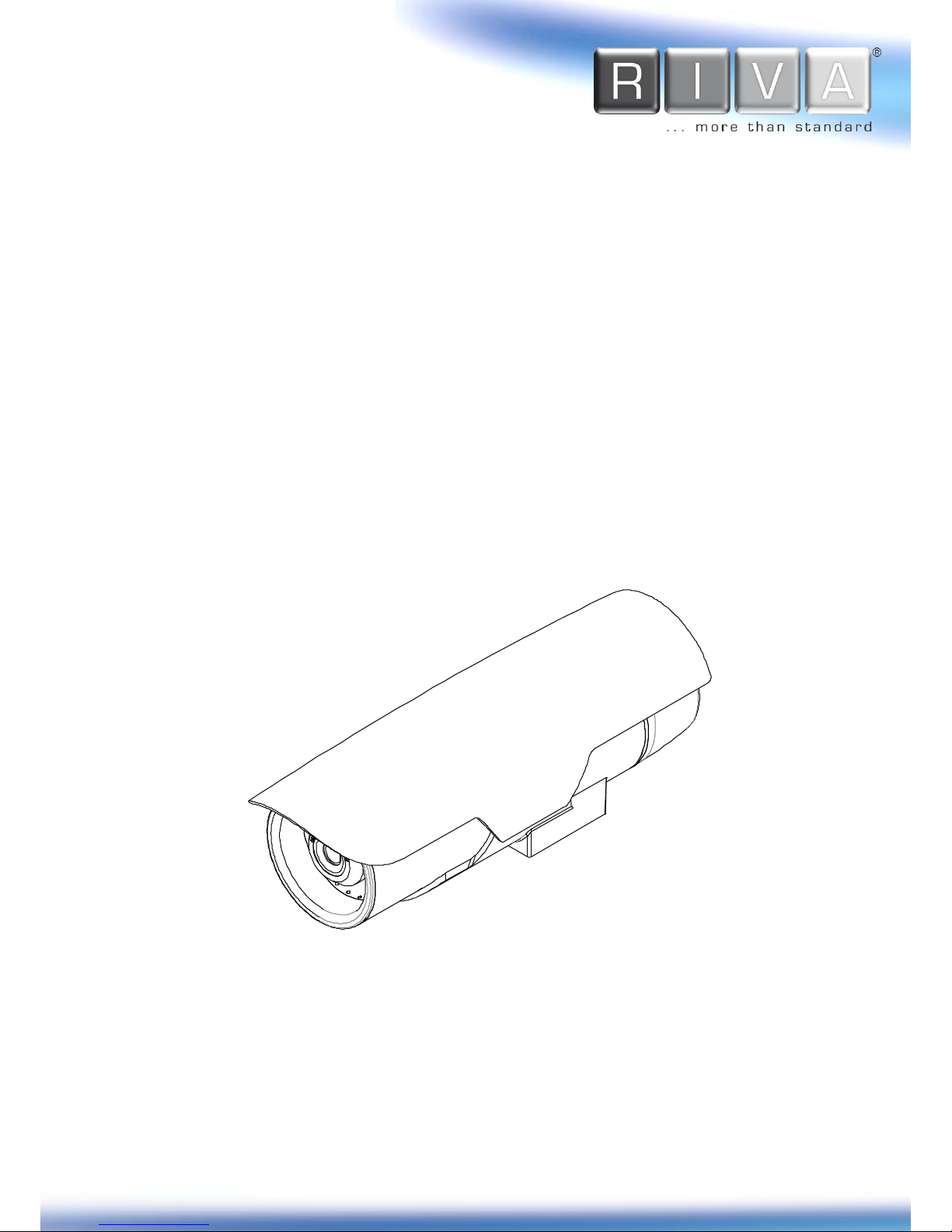
RTC6500 Thermal Camera
Series
Installation Guide
Page 2

RTC Series RTC6500 Series Installation Guide
04-2017-A www.rivatech.de 2
Precaution
Please read this manual carefully before installing the unit.
Never disassemble the camera. Unauthorized disassembly may cause equipment
failure or damage to the unit.
Please do not install the camera in a place exposed to direct sunlight.
Do not operate the camera in environments beyond the specified temperature.
Refer to Environment Condition on APPENDIX (A): SPECIFICATIONS in this manual.
Before applying power to the camera, check the power source to ensure that it is
within the specifications. Refer to Electrical Characteristics on APPENDIX (A):
SPECIFICATIONS.
CAUTION: RISK OF EXPLOSION IF BATTERY IS REPLACED BY AN INCORRECT TYPE.
DISPOSE OF USED BATTERIES ACCORDING TO THE MANUFACTURER’S INSTRUCTIONS.
Page 3

RTC Series RTC6500 Series Installation Guide
04-2017-A www.rivatech.de 3
Table of Contents
Precaution ................................................................................................................ 2
1. FEATURES ............................................................................................................. 5
2. PACKAGE CONTENTS............................................................................................. 6
3. PART NAMES ........................................................................................................ 7
4. INSTALLATION ...................................................................................................... 9
4.1. Installing Cable Gland ............................................................................................ 9
4.2. Connecting Cable(s) ............................................................................................. 10
4.3. Installing Base Mount .......................................................................................... 10
4.4. Closing the Back Cover ......................................................................................... 11
4.5. Installing the Sunshield ........................................................................................ 11
4.6. Adjusting Image Focus ......................................................................................... 11
4.7. Installing with Bracket ......................................................................................... 12
5. CONNECTIONS .................................................................................................... 13
6. CONFIGURATION ................................................................................................ 16
6.1. Set up network environment ............................................................................... 16
6.1.1. Generic IP Environment ............................................................................................ 16
6.1.2. Custom IP Environment............................................................................................. 17
6.2. View video on web page ...................................................................................... 18
6.2.1. ActiveX Installation .................................................................................................... 18
6.2.2. View video using IPAdmin Tool ................................................................................. 19
6.3. Reboot .................................................................................................................. 20
6.4. Factory Default ..................................................................................................... 20
6.5. Safe Mode ............................................................................................................ 21
APPENDIX (A): SPECIFICATIONS .............................................................................. 23
Summary ..................................................................................................................... 23
Electrical Characteristics ............................................................................................. 24
Environment Condition ............................................................................................... 24
Mechanical Condition ................................................................................................. 24
APPENDIX (B): DETECTION RANGE .......................................................................... 25
APPENDIX (C): POWER OVER ETHERNET .................................................................. 27
Power Comparison ...................................................................................................... 27
Page 4

RTC Series RTC6500 Series Installation Guide
04-2017-A www.rivatech.de 4
APPENDIX (D): DIMENSIONS ................................................................................... 28
APPENDIX (E): HEXADECIMAL-DECIMAL CONVERSION TABLE .................................. 29
REVISION HISTORY ................................................................................................. 30
Page 5

RTC Series RTC6500 Series Installation Guide
04-2017-A www.rivatech.de 5
1. FEATURES
Camera
17 ㎛ uncooled vanadium oxide micro-bolometer
320x240 / 640x480 resolutions
6, 9, 16, 24, 42,60 degrees field of view (RTC6500Q)
12, 18, 25, 37, 50 degrees field of view (RTC6500V)
Weather Proof (IP66)
Video
H.264 and MJPEG(Motion JPEG)
Max 9 fps or 30 fps in all available resolutions depending on the camera model
Text Overlay
Video Motion Detection supported
Audio
Two-way audio streaming
Audio compression: G.711 µLaw
Network
RTSP/ HTTP protocol supported
10/100 Base-T Ethernet
Sensor/Alarm
1 Digital Input / 2 Digital Outputs
Integration
Software Development Kit (SDK)
ONVIF compliant (Profile S & Profile G)
Additional Features
microSDHC card embedded (optional)
RS-485 supported
DC12V, AC24V, or PoE
VCA (Video Content Analysis)
VCA Detect (Included as basic)
Page 6

RTC Series RTC6500 Series Installation Guide
04-2017-A www.rivatech.de 6
2. PACKAGE CONTENTS
Please unpack the package carefully and handle the equipment with care. The package
contains:
Note
i
The contents above are subject to change without prior notice.
Camera
(
Below is the sunshield attached image)
Sunshield
DC Power Jack Cable
Tamper Resistant Screws x 8
Base Mount
Terminal Blocks
Stem Bumpers x 2 and 1
Spare
Cable Gland & Electrical Nut & O-ring
Silica Gel Packet
Quick Start Guide
Screw &
Plastic Anchor-3pcs
Screw &
Plastic Anchor-3pcs
Screw &
Plastic Anchor-3pcs
Screw &
Plastic Anchor-3pcs
Quick Installation Guide
Screw &
Plastic Anchor-3pcs
Quick Installation Guide
Screw &
Plastic Anchor-3pcs
Screw &
Plastic Anchor-3pcs
Quick Installation Guide
CABEL CORE
Page 7

RTC Series RTC6500 Series Installation Guide
04-2017-A www.rivatech.de 7
3. PART NAMES
① Sunshield
It prevents the lens from getting the direct sunlight.
② NTSC / PAL Button
The button switches the video output mode between NTSC and PAL.
Pressing the button will maintain the current video output mode unless pressing once more
to switch to the other mode.
③ Analogue Video Output
Connect a BNC output cable to see video via an analogue monitor.
④ RJ45 Socket
RJ45 LAN connector for 10/100 Base-T Ethernet (PoE supported).
⑤ Reset Button
Pressing this button reboots the camera or initializes the current settings of the camera to
the factory default settings. Refer to 6.3. Reboot and 6.4. Factory Default for the pressing
duration and more information.
⑥ Terminal Connectors for DI/DO
Connecting terminal blocks for digital input (sensor) and digital outputs (alarms)
Refer to 5. CONNECTIONS for more information.
⑦ Terminal Connectors for Audio In/Out
Connecting terminal blocks for audio input (microphone) and audio output (speaker)
Refer to 5.CONNECTIONS for more information.
⑧ Terminal Connector for RS-485
Connecting terminal blocks for RS-485
Refer to 5.CONNECTIONS for more information.
NTSC / PAL Button
Analogue Video Output
Sunshield
RJ45 Socket
CABEL CORE
[ Camera Profile Image ]
[ Back Panel of Camera ]
Reset Button
Terminal Connectors
for DI/DO
Terminal Connectors
for Audio In/Out
Terminal Connectors
for RS-485
* The model herein and its appearance are subject to change without any prior notice.
Terminal
Connectors
for power adaptor
Page 8

RTC Series RTC6500 Series Installation Guide
04-2017-A www.rivatech.de 8
⑨ Terminal Connector for Power Adaptor
Connect terminal blocks for power supply
Refer to 5.CONNECTIONS for more information.
Page 9
RTC Series RTC6500 Series Installation Guide
04-2017-A www.rivatech.de 9
4. INSTALLATION
4.1. Installing Cable Gland
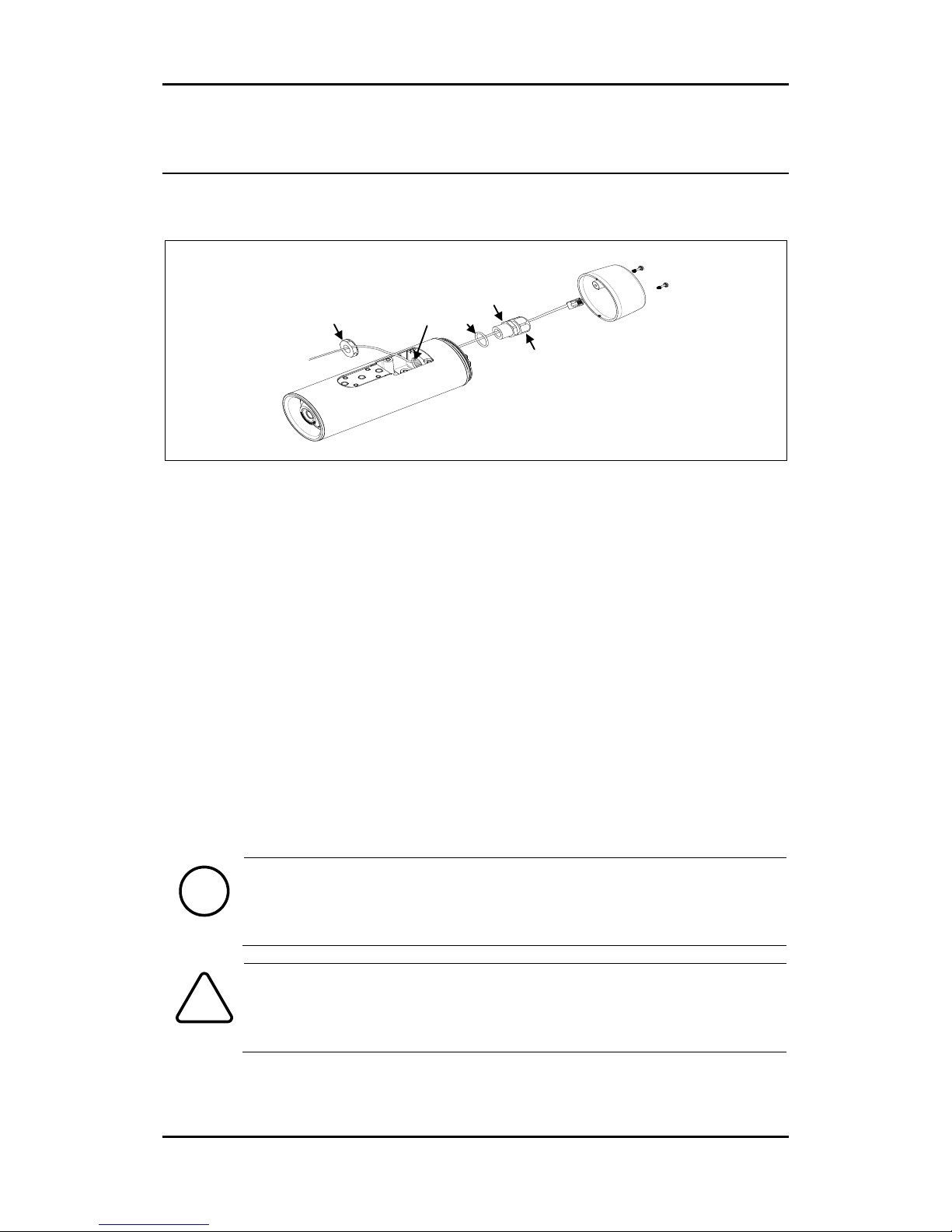
1) Detach the back cover by twisting it counter-clockwise.
2) Disassemble the provided cable gland unit. There will be an electrical nut, a rubber sealing
ring inserted inside the cable gland, a gland body, and a sealing nut.
3) Pass the electrical nut through the ends of the necessary cables.
4) Pass the cables through the holes both on the back and the bottom of the camera by
referring to the image above.
5) Pass the provided O-ring and gland body through the ends of the cables that are on the
backside of the camera.
6) Insert the cables into the rubber sealing ring at the point where about 4.5 inches (11.5 cm)
of the cable ends remains to connect to the corresponding connectors on the back panel later.
7) Push the rubber sealing ring through the claw of the gland body.
8) Insert the sealing nut into the thread of the gland body, and tighten it by turning the nut on
the thread. The rubber sealing ring will be tightened to fill the gap between the rubber sealing
ring and the cables.
9) Push the gland unit through the hole on the back of the camera so that the other end of the
thread on the gland unit will be inserted into the hole for gland near the bottom of the camera
body.
10) Fix the gland unit to the hole by inserting the electrical nut and tightening it on the thread
of the gland unit.
Note
i
When you insert a video out cable together with other cables such as RJ45, DIDO,
and audio cables, a thin type of the BNC cable is recommended as the standard
BNC cable is too thick to be inserted together with the other cables into the
rubber sealing ring.
Caution
!
Use the detachable cable with a separate BNC connector to pass the hole of the
sealing nut. Otherwise, use the female type head of the BNC cable to pass the
hole of the sealing nut.
Hole for gland
Electrical nut
O-ring
Gland body
Sealing nut
Page 10
RTC Series RTC6500 Series Installation Guide
04-2017-A www.rivatech.de 10
4.2. Connecting Cable(s)
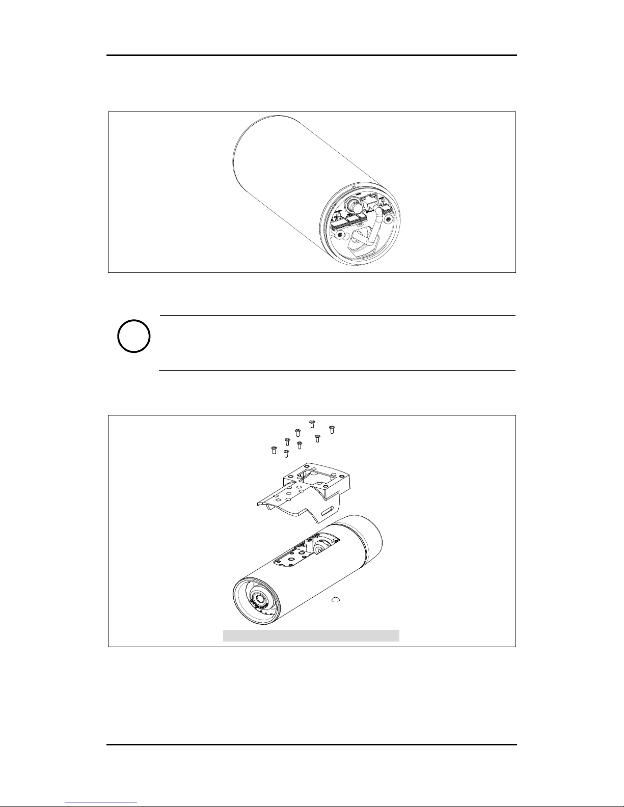
Connect the required cables to the corresponding connectors on the back panel of the camera
body. Refer to 5. CONNECTIONS for more information about each connector.
Note
i
Please use a shielded cable for the RJ45 connection to block radio frequency
interference.
4.3. Installing Base Mount
1) Insert the provided 8 tamper resistant screws to the corresponding screw holes on the base
mount by referring to the image above.
2) Tighten them with a Phillips head #2 screwdriver to fix the base mount to the camera.
[Base Mount Installation: Upside-Down View]
Page 11
RTC Series RTC6500 Series Installation Guide
04-2017-A www.rivatech.de 11
4.4. Closing the Back Cover
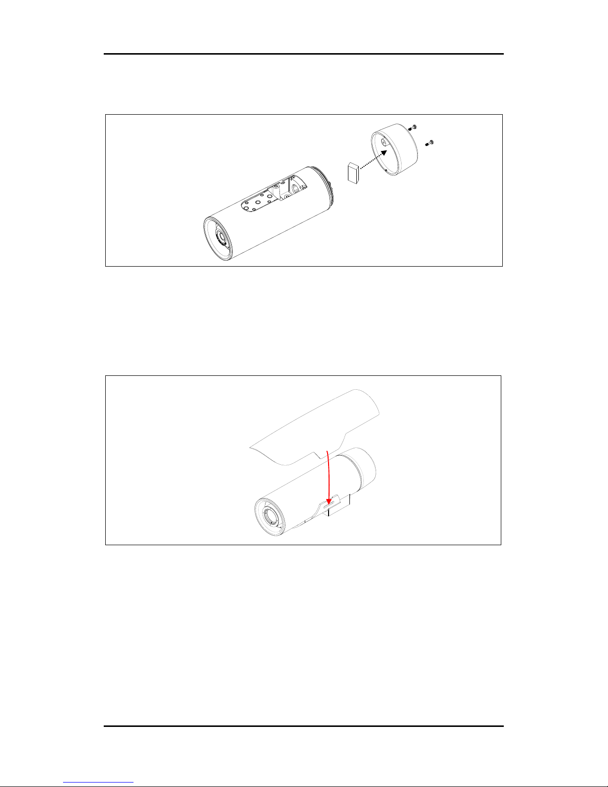
1) Insert the provided silica gel packet inside the back panel.
2) Close the back panel of the camera by twisting the back cover clockwise on the camera’s
back panel.
3) Insert the two tamper resistant screws into the holes on the back cover, and tighten them
with a Phillips #2 screwdriver to fix the back cover to the camera unit.
4.5. Installing the Sunshield
1) Insert the two provided stem bumpers to the holes at the bottom of the sunshield.
2) Place the sunshield on top of the camera body, and snap the sunshield to the base mount.
4.6. Adjusting Image Focus
The camera is pre-focused at factory to suit each FOV. However, in case you need to adjust the
focus for optimal image quality at your installation site, you can manually set the focus by
rotating the lens with hand.
The lens may be a little difficult to turn due to the O-ring behind the lens. Try to turn the lens
counter-clockwise first to move the lens away from the base. Once the lens moves, start
turning it in either direction for focusing by grabbing the barrel of the lens with one hand and
grabbing the base unit with the other hand.
Page 12

RTC Series RTC6500 Series Installation Guide
04-2017-A www.rivatech.de 12
4.7. Installing with Bracket
The compatible accessories to mount this camera are as follows.
Model Names & Combinations
WBOVA2 + (WCWA, WSFPA / DBHWGC / PTCC1, or WCPA)
WCM4A2
Refer to the corresponding accessory model’s installation guide for the instructions.
Note
i
The models in the parenthesis, (), may or may not be required depending on
the installation environment.
Model Names
WBOVA2
Wall Mount Bracket
WCM4A2
Ceiling Mount Bracket
WCWA
Corner Mount Adaptor
WSFPA
Pole Mount Adaptor
DBHWGC
Pole Mount Adaptor
PTCC1
Pole Mount Adaptor
WCPA Reinforcing Support Plate
for Poor Consistency Walls
Page 13
RTC Series RTC6500 Series Installation Guide
04-2017-A www.rivatech.de 13
5. CONNECTIONS
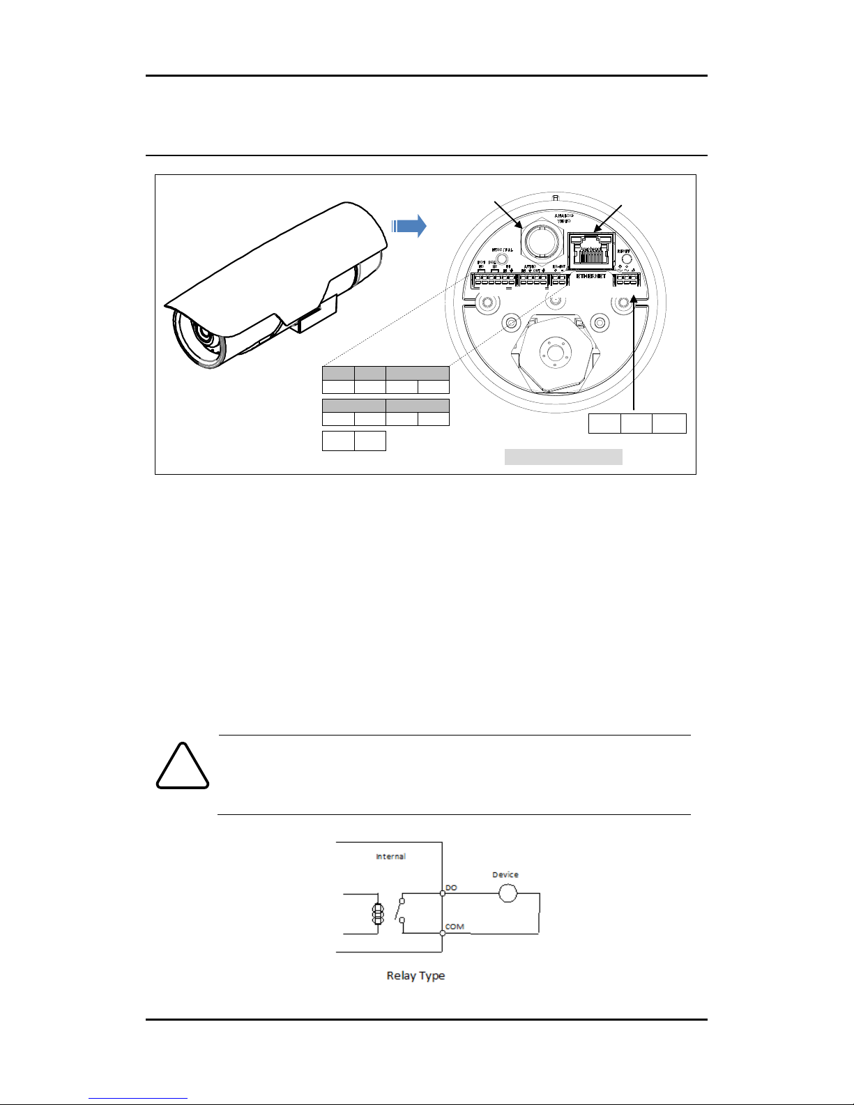
① DIDO (Sensor/Alarm) Connection
Two Alarms (DO1 | DO2)
The camera provides two digital outputs (alarms). The default status of each is respectively
normally open(N.O) and normally closed(N.C) so that you can opt to use one accordingly.
Only the relay type is supported.
- Digital Output 1
Relay Rating: Max 30VDC 1A
Normally Open (N.O) at power off
- Digital Output 2
Relay Rating: Max 30VDC 1A
Normally Closed (N.C) at power off
Caution
!
Do not exceed the maximum relay rating.
DO1
DO2
DI
NO
NC
IN
GND
AUDIO IN
AUDIO OUT
IN
GND
OUT
GND
+
-
DIDO
AUDIO
RS-485
Screw &
Plastic Anchor-3pcs
Quick Installation Guide
CABEL CORE
AUDIO
POWER
RS-485
ANALOGUE
VIDEO OUT
RJ45
+
-
GND
POWER
[ Back Panel of Camera ]
Page 14
RTC Series RTC6500 Series Installation Guide
04-2017-A www.rivatech.de 14
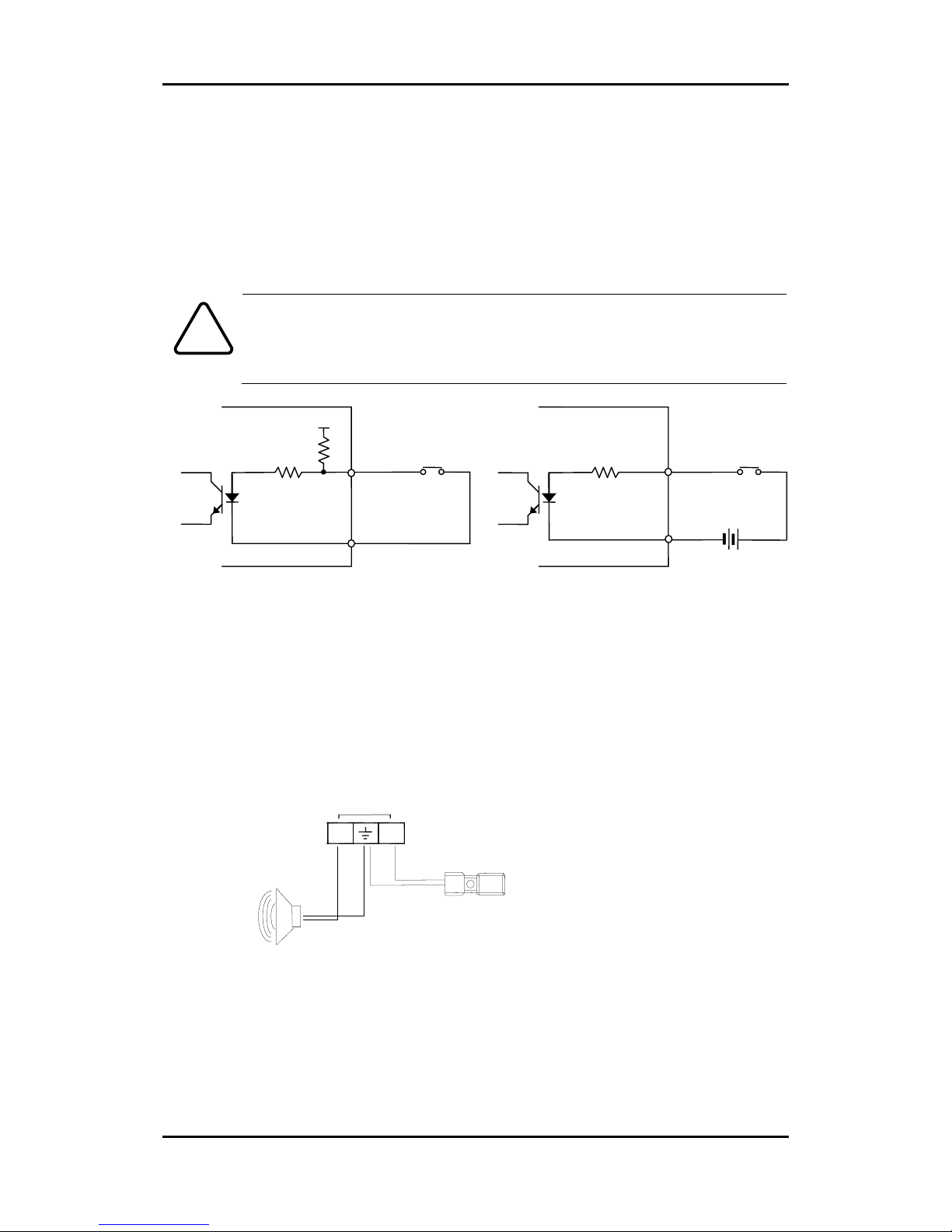
One Sensor (DI)
The camera provides one digital input (sensor).
Sensor (DI) can be connected to either a voltage type sensor or a relay type sensor as the
following figures. Settings can be done through the camera’s webpage.
- Input voltage range: 0VDC minimum to 5VDC maximum, Max 50mA
Relay Rating: Max 30VDC 1A
Caution
!
Do not exceed the maximum input voltage or relay rate.
② Audio Connection
The camera provides a mono audio input and output. Due to low audio output power, an
amplified speaker is recommended for enhanced sound (Refrain from connecting a
headphone or an earphone directly to the camera).
- Microphone In: Max 2Vp-p, 20KΩ (90dB)
- Headphone Out: 60mW, 16Ω (95dB)
Mic
Amp Speaker
ETHERNET
MICRO SD
DC12V
OutOut
In
AUDIO
+
Reset
+3.3V
DI
COM
DI
COM + -
Relay Type
Voltage Type
+
-
Output of
Sensor
Output of
Sensor
Internal
Internal
+
-
Page 15
RTC Series RTC6500 Series Installation Guide
04-2017-A www.rivatech.de 15
③ RS-485 Connection
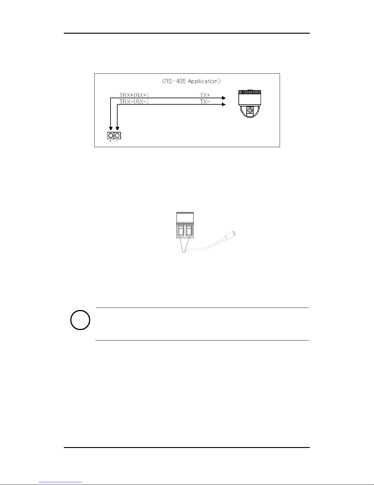
The RS-485 serial port consists of TRX+(RX+) and TRX-(RX-) like the following image.
④ Power Connection
The camera can be powered by either 12VDC, 24VAC, or PoE. If the camera is powered via
PoE, you do not need to connect the power adaptor. For more information about PoE,
refer to “Appendix (C). Power over Ethernet” for more information.
To operate your camera by using 12VDC, make sure the polarity is correct before
connecting the power cable. Incorrect connection may cause damage to the device.
⑤ RJ45 Connection
This is a RJ45 LAN connector for 10/100 Base-T Ethernet. Use the Ethernet cable (RJ45) to
connect the device to a hub or a router in the network. Refer to “Appendix (C). Power
over Ethernet” for more information.
Note
i
Please use a shielded cable for the RJ45 connection to block radio frequency
interference.
⑥ Analogue Video Output Connection
Use a 75 ohm video coaxial cable to connect to a monitor’s analog video input.
The factory default for analogue video output is NTSC. Press once to set the video to PAL,
and press again to set the video to NTSC.
Black
Red
485 Device
Page 16
RTC Series RTC6500 Series Installation Guide
04-2017-A www.rivatech.de 16
6. CONFIGURATION
6.1. Set up network environment
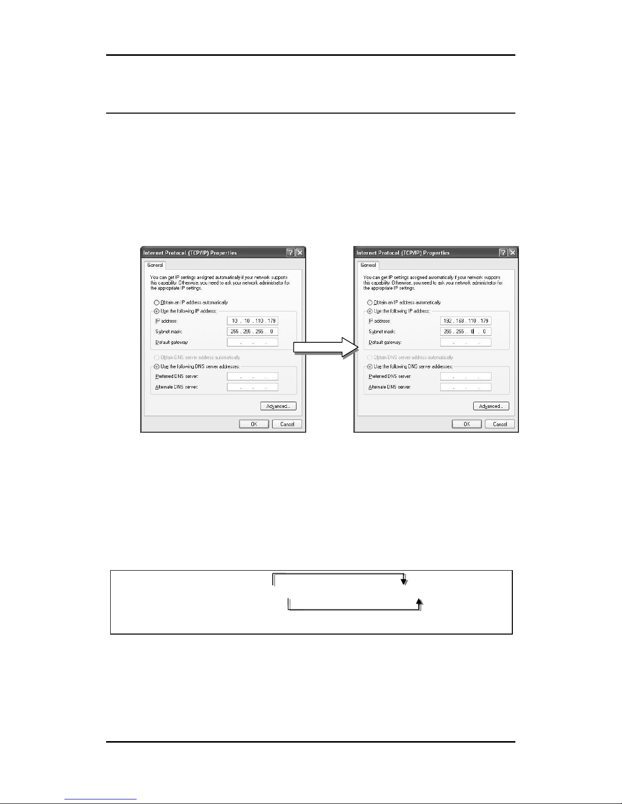
The default IP address of the device is 192.168.XXX.XXX. Users can identify the IP address of the
device from converting the MAC address’s hexadecimal numbers, which is attached to the
device. Be sure that the device and PC are on a same network before running the installation.
IP address : 192.168.xxx.xxx
Subnet mask: 255.255.0.0
6.1.1. Generic IP Environment
In case of generic private network environment where IP address 192.168.XXX.XXX are used,
users may view the live streaming images on a web page using the device’s default IP address:
1. Convert the device’s MAC address to the IP address. Refer to the Hexadecimal-Decimal
Conversion Chart at the end of the manual.
(The MAC address of the device is attached on the side or bottom of the device.)
2. Start the Microsoft® Internet Explorer web browser and enter the address of the device.
3. Web streaming and device configurations are supported through ActiveX program. When the
ActiveX installation window appears, authorize and install the ActiveX.
Convert the last two sets of hexadecimal numbers to decimal numbers.
Page 17
RTC Series RTC6500 Series Installation Guide
04-2017-A www.rivatech.de 17
6.1.2. Custom IP Environment
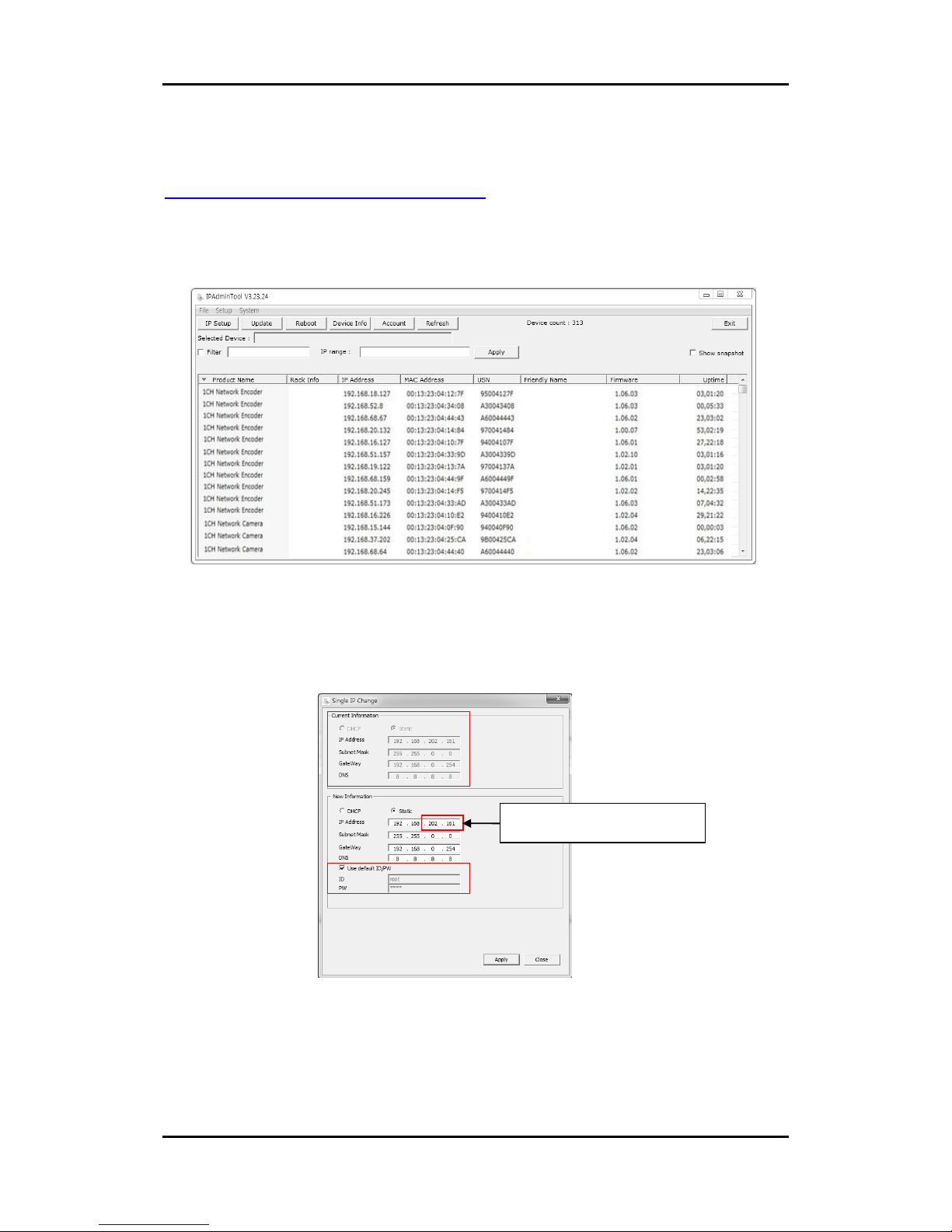
Please access our website and download necessary IPAdminTool first:
http://www.rivatech.de/en/downloads/software
IPAdminTool is a management tool, which automatically scans all of the network products for
users to perform administrative tasks, which includes network configurations, firmware
update, device reboot, and device organizations.
To modify the device’s default IP address for customized network area;
1. Find the device from the IPAdminTool’s list and highlight the device’s name.
2. Right-click the mouse and select IP Address; IP Setup window appears.
* There are two options that are for a single device or for multiple devices respectively. For one device, click “Single”.
3. On the New Information table in the Single IP Change window, modify the last two digits of
the device’s IP address. Make sure to input the correct ID and PW of the device (default:
root / pass).
4. Click Apply to complete the modification.
Give a new unique IP address by
modifying the last two digits.
Page 18
RTC Series RTC6500 Series Installation Guide
04-2017-A www.rivatech.de 18
6.2. View video on web page
Type the proper IP address to view the live streaming images through a web browser.
The default username and password is root / pass.
6.2.1. ActiveX Installation
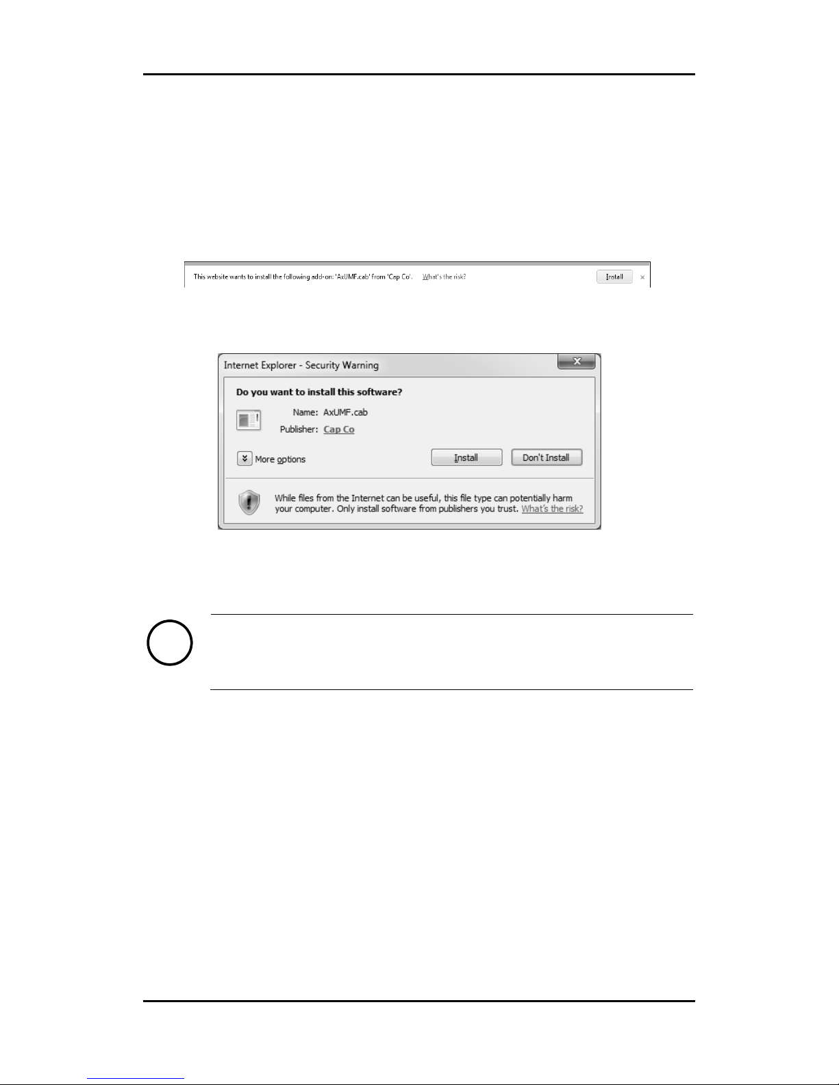
1. When the browser asks to install the AxUMF software, click Install to proceed.
2. When Setup installation pop-up window appears, click Install to proceed with rest of
installations.
Note
i
Depending on system OS and Internet Explorer version, installation experience
may differ from one another. Figures described above are from Windows 7,
Internet Explorer 9 environment.
Page 19
RTC Series RTC6500 Series Installation Guide
04-2017-A www.rivatech.de 19
6.2.2. View video using IPAdmin Tool
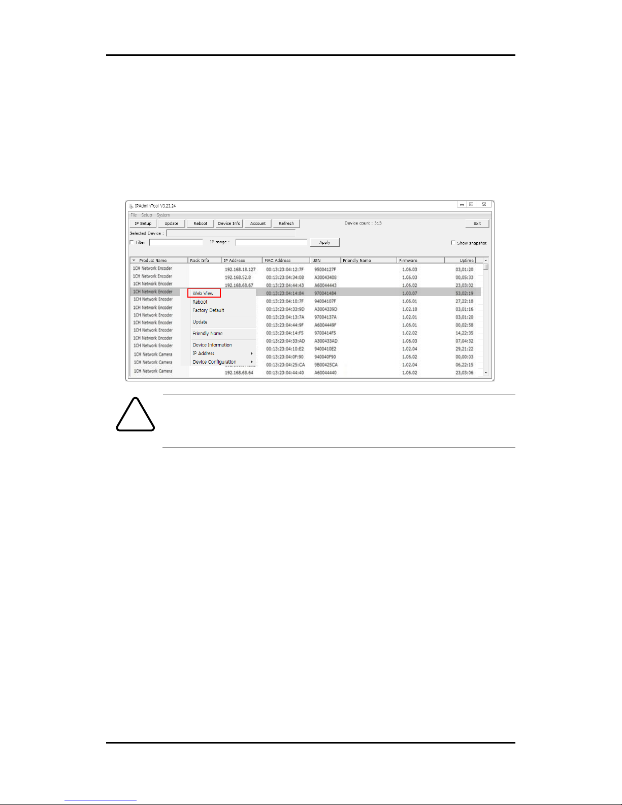
IPAdminTool automatically searches all activated network encoders and IP cameras and shows
the product name, IP address, MAC address and etc.
1. From the IPAdminTool’s product list, select the device by highlighting it.
2. Right-click the mouse, and select Web view.
Then, the system’s default web browser opens the device’s address.
Caution
!
Whether directly accessing the streaming video by typing IP address on a web
page or taking steps through IPAdminTool, the ActiveX is needed to be installed
for the Microsoft® Internet Explorer to have the complete configuration
privileges.
Page 20
RTC Series RTC6500 Series Installation Guide
04-2017-A www.rivatech.de 20
6.3. Reboot
On the Device
Perform the following procedure to reset your device.
1. Press the reset button for 2 seconds when the device is powered on.
2. Wait for the system to reboot.
Caution
!
Do not press the reset button for more than 2 seconds. Otherwise, the camera
may be switched to its factory default settings.
On the Webpage
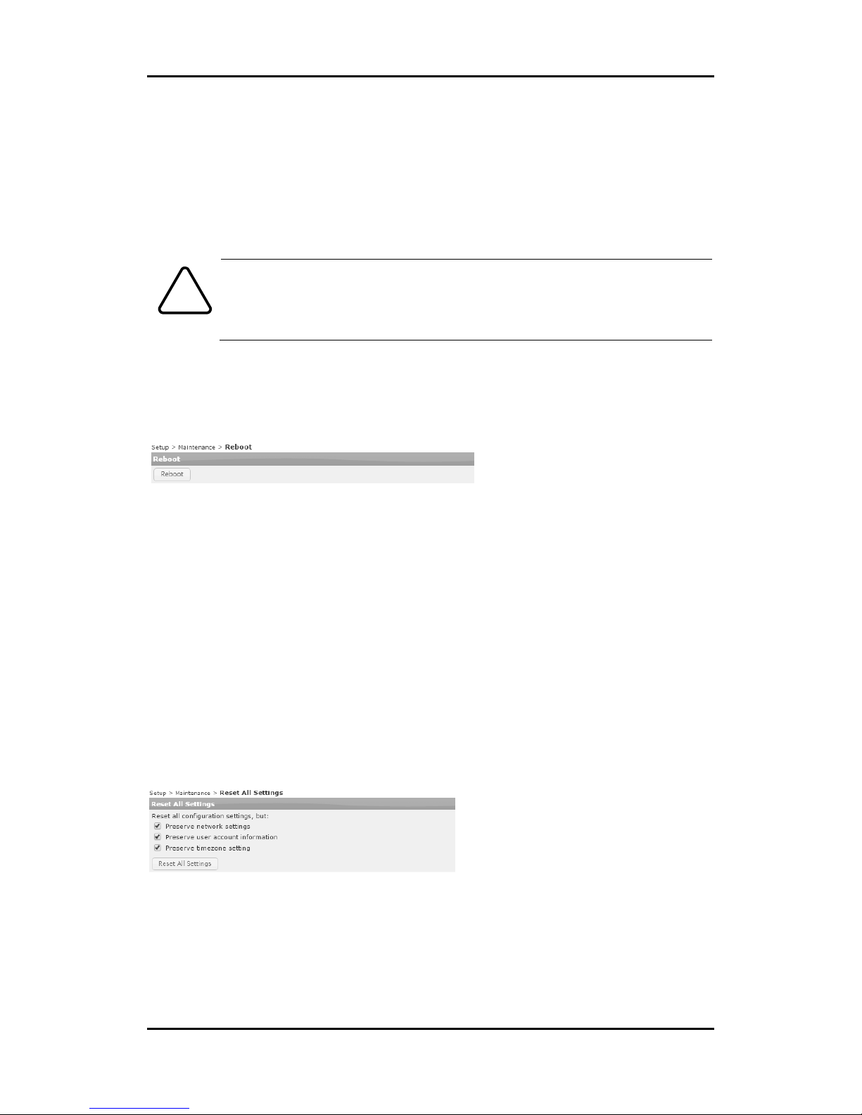
Reboot the device via the camera’s webpage:
1. Go to Setup > Maintenance > Reboot.
2. Click the Reboot button to reboot the device.
3. Wait for the device to complete booting.
6.4. Factory Default
Resetting the device back to the factory default will initialize all parameters including the IP
address back to the factory defaults.
On the Device
1. Press the reset button for 10 seconds by making sure that booting is complete on the
device.
2. Wait for the system to reboot.
Then, all the parameters of the device will be initialized.
On the webpage
Reset the current settings to the factory default values via the camera’s webpage:
1. Go to Setup > Maintenance > Reset All Settings.
2. Select the items that you want to preserve from the initialization among network
settings, user account information, and time zone setting.
3. Click Reset All Settings.
Page 21

RTC Series RTC6500 Series Installation Guide
04-2017-A www.rivatech.de 21
Note
i
The factory default settings can be inferred with the following information:
IP address: 192.168.xx.yy
Network mask: 255.255.0.0
Gateway: 192.168.0.1
User ID: root
Password: pass
6.5. Safe Mode
What is Safe Mode?
There may be certain occasions that your camera repeatedly fails to boot. Then, your camera
may enter safe mode to be recovered from the occasions.
What may have caused Safe Mode?
Here below are the main typical causes.
* The power supply is continually unplugged certain times in the middle of system booting.
* The firmware files required for system booting are damaged.
* There are conflicts in the system settings.
How to recover your system from Safe Mode
The messages above will appear on the webpage when your device has been rebooted in safe
mode. Then, you should follow the instructions on the webpage according to each step.
Note
i
There is another method to update firmware, which is using IPAdminTool.
Please refer to ‘IPAdminTool User’s Manual.pdf’ for the detailed procedure.
Browse
Page 22

RTC Series RTC6500 Series Installation Guide
04-2017-A www.rivatech.de 22
Note
i
If your device is still in safe mode after trying to update firmware, please contact
your local agency to get further assistance.
Page 23

RTC Series RTC6500 Series Installation Guide
04-2017-A www.rivatech.de 23
APPENDIX (A): SPECIFICATIONS
Summary
Camera Module
Array Size
RTC6500Q: 320x240
RTC6500V: 640x480
Detection Type
Uncooled Vanadium Oxide Microbolometer
Sensor pixel size
17um
Spectral Response
8-14 μm
Lens
RTC6500Q: 6°, 9°, 16°, 24°, 42°, 60°
RTC6500V: 12°, 18°, 25°, 37°, 50°
Sensitivity
Less than 50mK
Scanning System
Progressive Scan
Video
Compression Format
H.264 Baseline, Main, High profile(MPEG-4 Part 10/ AVC),
MJPEG(Motion JPEG)
Number of Streams
Dual Stream, Configurable
Resolution
RTC6500Q
640x480 (VGA, Scaled-up)
320x240 (QVGA)
160x120 (QQVGA)
RTC6500V
640x480 (VGA)
320x240 (QVGA)
160x120 (QQVGA)
Frame Rate
Configurable up to 30 FPS or 9 FPS
Motion Detection
Built-in
Burnt-in Text (Digital)
Time stamp and text caption overlay
Analogue Output
NTSC/PAL
Audio
Input/output
1/1 channel
Compression Format
G.711
Function
Digital Input/output
1/2 channels
RS-485
Supported
Network
10/100 Base-T
Power over Ethernet (PoE)
Supported
Protocol
QoS Layer 3 DiffServ, TCP/IP, UDP/IP, HTTP, HTTPS, RTSP,
RTCP, RTP/UDP, RTP/TCP, mDNS, UPnP™, SMTP, DHCP, DNS,
DynDNS, NTP, SNMPv2c/v3(MIB-II), IGMP, ICMP, SSLv2/v3,
TLSv1/1.2, SRTP, RTMP, IEEE802.1X
Page 24

RTC Series RTC6500 Series Installation Guide
04-2017-A www.rivatech.de 24
Storage
1 x microSDHC card embedded (optional)
Electrical Characteristics
Power Source
DC 12V (CLASS 2, LPS)/ AC 24V / PoE IEEE802.3af (Class 0)
Power Consumption
Max 10W@12VDC
Audio Input
MIC in, Max2Vp-p, 20KΩ (90dB)
Audio Output
Line out, 60mW, 16Ω (95dB)
D/I
Max 50mA@5VDC, TTL level 1.5V threshold
D/O 1
D/O 2
Max 1A@30VDC
Environment Condition
Operating Temperature
[DC12V/PoE] -40°C ~ 60°C (-40°F ~ 140°F)
Operating Humidity
Up to 85% RH
Mechanical Condition
Material
Poly-carbonate, Aluminum
Dimension
3.7” x 3.9” x11.5” (95 x 98 x 293 mm)
Weight (Approx.)
1.2kg (2.65lb)
Page 25
RTC Series RTC6500 Series Installation Guide
04-2017-A www.rivatech.de 25
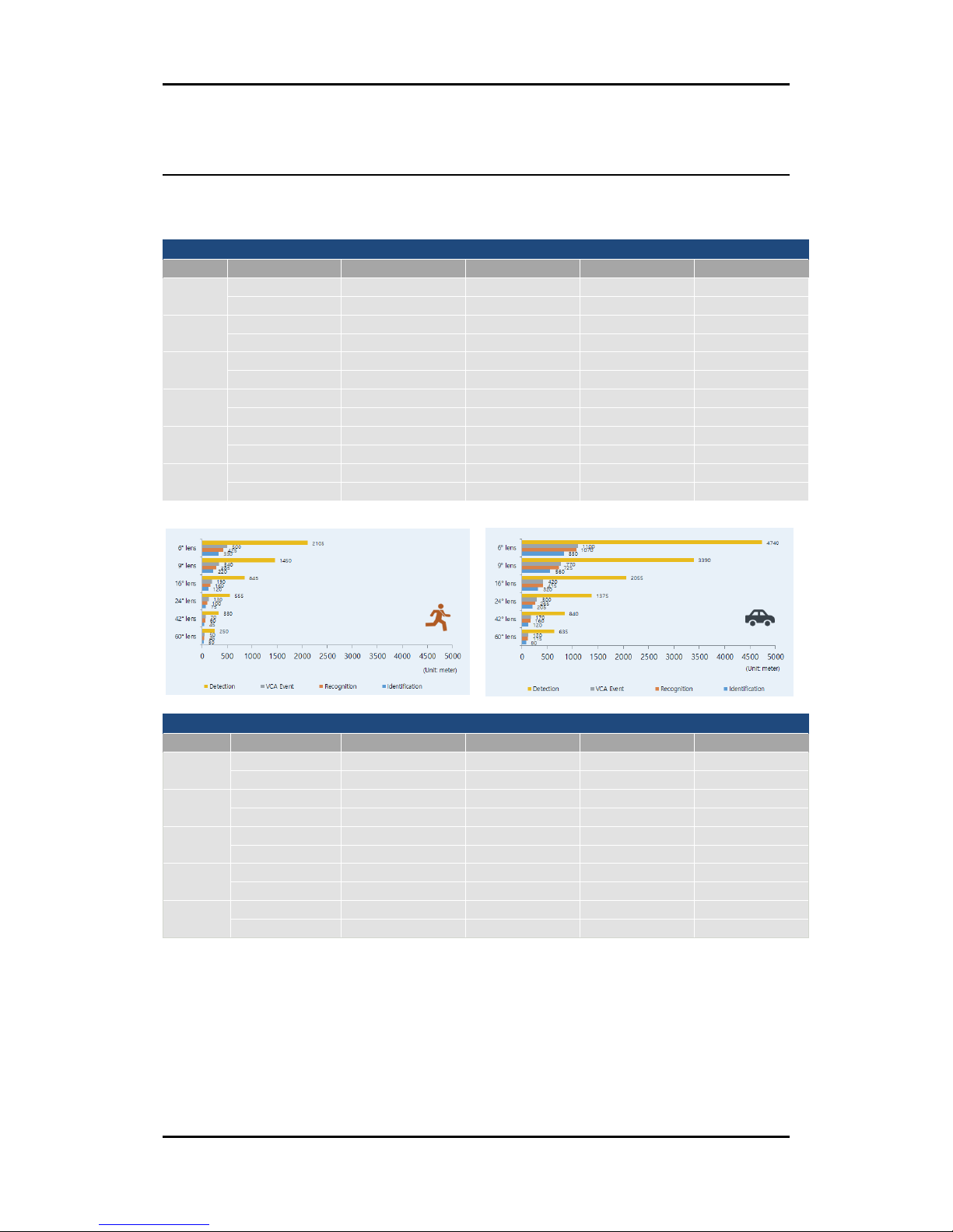
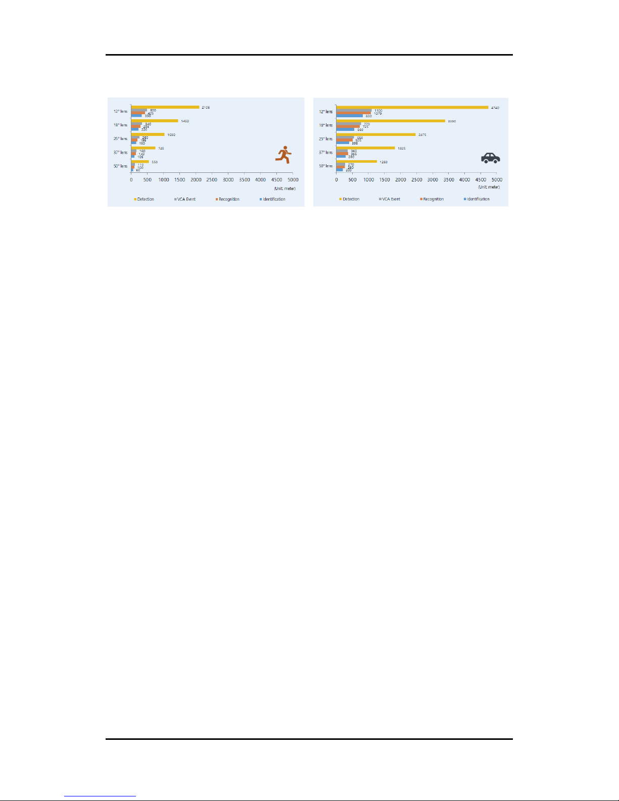
APPENDIX (B): DETECTION RANGE
*The detection range is of the maximum values.
(Unit: meter)
RTC6500Q
Lens
Object
Detection
VCA Event
Recognition
Identification
6°
Person
2,105
500
425
330
Vehicle
4,740
1100
1,070
830
9°
Person
1,450
340
285
220
Vehicle
3,390
770
725
560
16°
Person
845
190
160
120
Vehicle
2,055
420
415
320
24°
Person
555
130
100
75
Vehicle
1,375
300
265
205
42°
Person
330
70
60
45
Vehicle
840
170
160
120
60°
Person
250
50
45
30
Vehicle
635
120
115
80
RTC6500V
Lens
Object
Detection
VCA Event
Recognition
Identification
12°
Person
2,105
500
425
330
Vehicle
4,740
1,100
1,079
830
18°
Person
1,450
340
285
220
Vehicle
3,390
770
725
560
25°
Person
1,030
250
195
150
Vehicle
2,475
550
505
395
37°
Person
745
160
140
105
Vehicle
1,825
360
365
280
50°
Person
550
110
100
60
Vehicle
1,260
270
260
200
Person
Vehicle
Page 26
RTC Series RTC6500 Series Installation Guide
04-2017-A www.rivatech.de 26
Person
Vehicle
Page 27

RTC Series RTC6500 Series Installation Guide
04-2017-A www.rivatech.de 27
APPENDIX (C): POWER OVER ETHERNET
The Power over Ethernet (PoE) is designed to extract power from a conventional twisted pair
Category 5 Ethernet cable, conforming to the IEEE 802.3af Power-over-Ethernet (PoE)
standard.
IEEE 802.3af allows for two power options for Category 5 cables.
The IEEE 802.3af-2003 standard allows up to 15.4 W of power the device. However, 12.95W is
the available power, as some power gets lost in the cable. The updated IEEE 802.3at-2009
(PoE+) standard allows up to 25.5 W (Max 34.2 W) of power the device.
PoE has advantages over conventional power in such places where AC powers cannot be
reached or is expensive to wire.
Power Comparison
Property
802.3af
802.3at
Available Power
12.95 W
25.50 W
Max. Power by PSE
15.40 W
34.20 W
Max. Current
350 mA
600 mA
Supported Cable
Category 3 or higher
Category 5 or higher
For proper activation of PoE, the Category 5 cable must be shorter than 100m and
conform the PoE standard.
With non-Power Sourcing Equipment (non-PSE)
When it is connected with non PSE, the power adaptor should be connected.
With power adaptor
Connecting both PSE and power adaptor does not do any harm to the product.
Disconnecting PSE or power adaptor from device does not reboot the device as
long as either one is connected to the device.
Note
i
Note
i
Page 28
RTC Series RTC6500 Series Installation Guide
04-2017-A www.rivatech.de 28
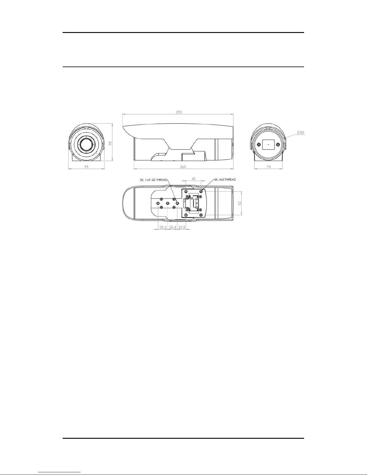
APPENDIX (D): DIMENSIONS
(Unit: mm)
Page 29

RTC Series RTC6500 Series Installation Guide
04-2017-A www.rivatech.de 29
APPENDIX (E): HEXADECIMAL-DECIMAL
CONVERSION TABLE
Refer to the following table when you convert the MAC address of your device to IP address.
Hex
Dec
Hex
Dec
Hex
Dec
Hex
Dec
Hex
Dec
Hex
Dec
Hex
Dec 0 0
25
37
4A
74
6F
111
94
148
B9
185
DE
222 1 1
26
38
4B
75
70
112
95
149
BA
186
DF
223 2 2
27
39
4C
76
71
113
96
150
BB
187
E0
224
3 3 28
40
4D
77
72
114
97
151
BC
188
E1
225 4 4
29
41
4E
78
73
115
98
152
BD
189
E2
226 5 5
2A
42
4F
79
74
116
99
153
BE
190
E3
227
6 6 2B
43
50
80
75
117
9A
154
BF
191
E4
228 7 7
2C
44
51
81
76
118
9B
155
C0
192
E5
229 8 8
2D
45
52
82
77
119
9C
156
C1
193
E6
230 9 9
2E
46
53
83
78
120
9D
157
C2
194
E7
231
0A
10
2F
47
54
84
79
121
9E
158
C3
195
E8
232
0B
11
30
48
55
85
7A
122
9F
159
C4
196
E9
233
0C
12
31
49
56
86
7B
123
A0
160
C5
197
EA
234
0D
13
32
50
57
87
7C
124
A1
161
C6
198
EB
235
0E
14
33
51
58
88
7D
125
A2
162
C7
199
EC
236
0F
15
34
52
59
89
7E
126
A3
163
C8
200
ED
237
10
16
35
53
5A
90
7F
127
A4
164
C9
201
EE
238
11
17
36
54
5B
91
80
128
A5
165
CA
202
EF
239
12
18
37
55
5C
92
81
129
A6
166
CB
203
F0
240
13
19
38
56
5D
93
82
130
A7
167
CC
204
F1
241
14
20
39
57
5E
94
83
131
A8
168
CD
205
F2
242
15
21
3A
58
5F
95
84
132
A9
169
CE
206
F3
243
16
22
3B
59
60
96
85
133
AA
170
CF
207
F4
244
17
23
3C
60
61
97
86
134
AB
171
D0
208
F5
245
18
24
3D
61
62
98
87
135
AC
172
D1
209
F6
246
19
25
3E
62
63
99
88
136
AD
173
D2
210
F7
247
1A
26
3F
63
64
100
89
137
AE
174
D3
211
F8
248
1B
27
40
64
65
101
8A
138
AF
175
D4
212
F9
249
1C
28
41
65
66
102
8B
139
B0
176
D5
213
FA
250
1D
29
42
66
67
103
8C
140
B1
177
D6
214
FB
251
1E
30
43
67
68
104
8D
141
B2
178
D7
215
FC
252
1F
31
44
68
69
105
8E
142
B3
179
D8
216
FD
253
20
32
45
69
6A
106
8F
143
B4
180
D9
217
FE
254
21
33
46
70
6B
107
90
144
B5
181
DA
218
FF
255
22
34
47
71
6C
108
91
145
B6
182
DB
219
23
35
48
72
6D
109
92
146
B7
183
DC
220
24
36
49
73
6E
110
93
147
B8
184
DD
221
Page 30

RTC Series RTC6500 Series Installation Guide
04-2017-A www.rivatech.de 30
REVISION HISTORY
MAN#
DATE(M/D/Y)
Comments
05-2016-A
05/02/2016
First release version
08-2016-A
08/11/2016
Added 4.6. Adjusting Image Focus
10-2016-A
10/13/2016
Added additional comments in 4.6. Adjusting Image Focus
10-2016-A
10/19/2016
Modified APPENDIX (B): DETECTION RANGE
Added more lenses
11-2016-A
11/22/2016
Added a note for RJ45 connection in 4.2. Connecting Cable(s)
and 5. CONNECTIONS
02-2017-A
02/07/2017
Added a protocol to the specification table
Updated APPENDIX (B): DETECTION RANGE
04-2017-A
04/04/2017
Updated a network protocol in the specification table (TLS ->
TLSv 1/1.2)
 Loading...