

Page 1
www.rivatech.de
RTC series
Installation Guide
Page 2
RTC Series RTC Installation Guide
01A.04 2
INFORMATION TO USER
CAUTION
RISK OF ELECTRIC SHOCK,
DO NOT OPEN
CAUTION: TO REDUCE THE RISK OF ELECTRIC SHOCK,
DO NOT REMOVE THE DEVICE COVER (OR BACK).
CONTACT QUALIFIED SERVICE PERSONNEL FOR INTERNAL
PART SERVICES.
This symbol is intended to alert the user the presence of uninsulated “dangerous voltage” within the product’s enclosure,
which may be sufficient magnitude to constitute an electric shock
risk to persons.
This symbol is intended to alert the user the presence of
important operating and maintenance (servicing) instructions
within the guide manual
!
!
Page 3

RTC Series RTC Installation Guide
01A.04 3
Table of Contents
1. FEATURES .............................................................................. 4
2. PACKAGE CONTENTS ................................................................ 5
3. PART NAMES .......................................................................... 6
3.1. Rear View .................................................................................... 6
3.2. Bottom View ................................................................................ 6
4. CONNECTIONS ........................................................................ 8
4.1.Connectors ................................................................................... 9
5. CONFIGURATION .................................................................... 12
5.1.Set up network environment .......................................................... 12
5.1.1. Generic IP Environment .......................................................... 12
5.1.2. Custom IP Environment .......................................................... 13
5.2. View video on web page ............................................................... 14
5.2.1. View video using IPAdmin Tool ................................................. 15
5.3. Reset ........................................................................................ 16
5.4. Factory Default ........................................................................... 16
APPENDIX (A): SPECIFICATIONS .................................................... 17
Summary .......................................................................................... 17
Environment Condition ........................................................................ 18
Mechanical Condition .......................................................................... 18
APPENDIX (B): THEORATICAL DISTANCE ........................................ 19
APPENDIX (C): POWER OVER ETHERNET ........................................ 20
PoE compatibility ................................................................................ 20
Power classification ............................................................................ 20
APPENDIX (D): DIMENSIONS ........................................................ 21
APPENDIX [E]: CAMERA HOUSING ................................................. 23
Housing Overview ............................................................................... 23
Positioning of Camera Mount by Lens .................................................... 23
Camera Installation ............................................................................ 24
To connect cables .............................................................................. 27
APPENDIX (F): HEXADECIMAL-DECIMAL CONVERSION TABLE ............. 28
REVISION HISTORY ..................................................................... 30
Page 4

RTC Series RTC Installation Guide
01A.04 4
1. FEATURES
Camera
17 ㎛ Next Generation Mirobolometer Technology
320x240 pixels
42, 19,12, 9 or 6 degrees field of view (Other lenses available upon
request)
Streaming
Dual streaming mode (such as different codec/resolution/bit rate and so
on.)
Burnt-in text supported
Unicast/Multicast supported
Video/Audio
Video compression: H.264/MPEG-4/MJPEG,
Audio compression: G.711(µLaw, aLaw)/PCM
Analog video out for external monitors
Video Motion Detection supported
Two-way mono audio supported
Network
RTSP/ HTTP protocol supported
10/100 Base-T Ethernet
Additional Features
RS-485 support
USB 2.0 support (Local storage)
Micro SD card support
PoE supported
Built-in Video Content Analysis
OSD support
SDK (Software Development Kit) provided
VCA (Video Content Analysis)
VCA Presence (Included as basic)
VCA Surveillance (Optional)
Page 5
RTC Series RTC Installation Guide
01A.04 5
2. PACKAGE CONTENTS
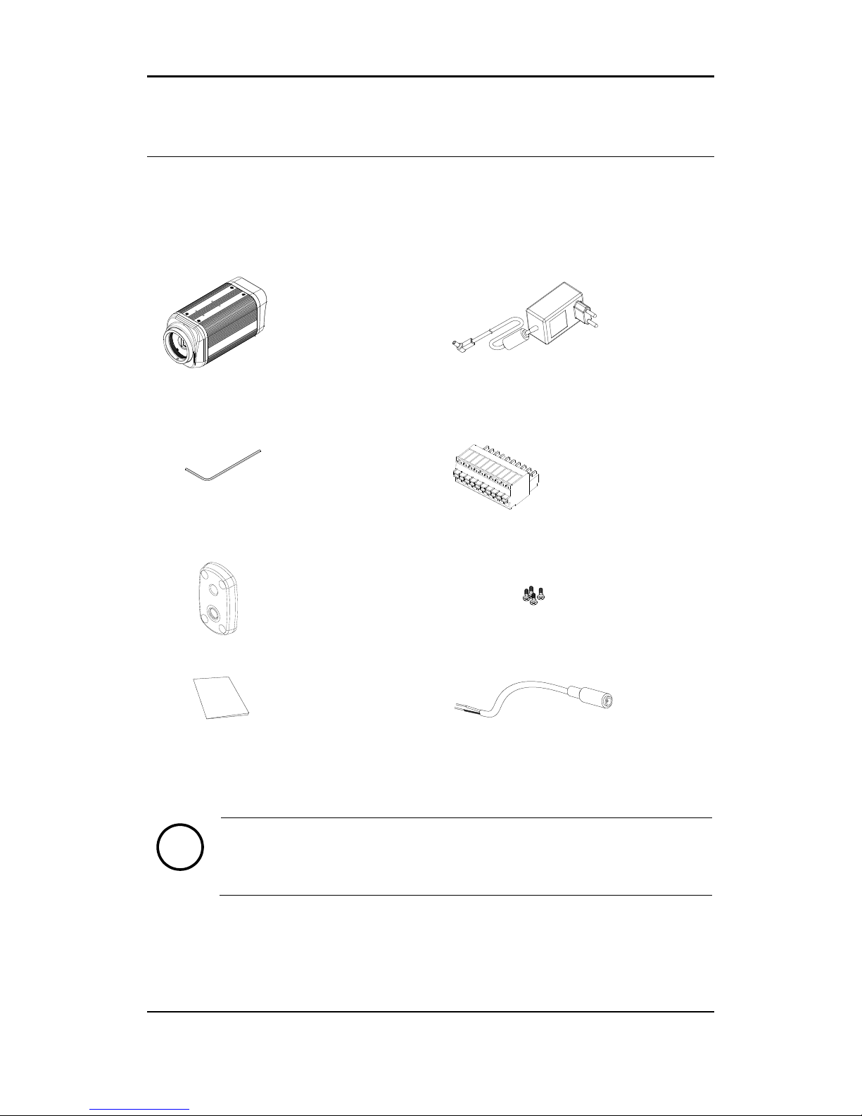
The package contains main camera, DC power adaptor, DC jack adaptor cable,
hex wrench driver, 9 pin terminal block, mounting adaptor, screws, and quick
installation guide. Unpack carefully and handle the equipment with care.
Camera
DC power adaptor
Hex wrench driver
9 Pin terminal block
Mounting Adaptor
Screws
Quick Installation Guide
DC Jack Adaptor Cable
The above contents are subject to change without prior notice.
Note
i
Page 6
RTC Series RTC Installation Guide
01A.04 6
3. PART NAMES
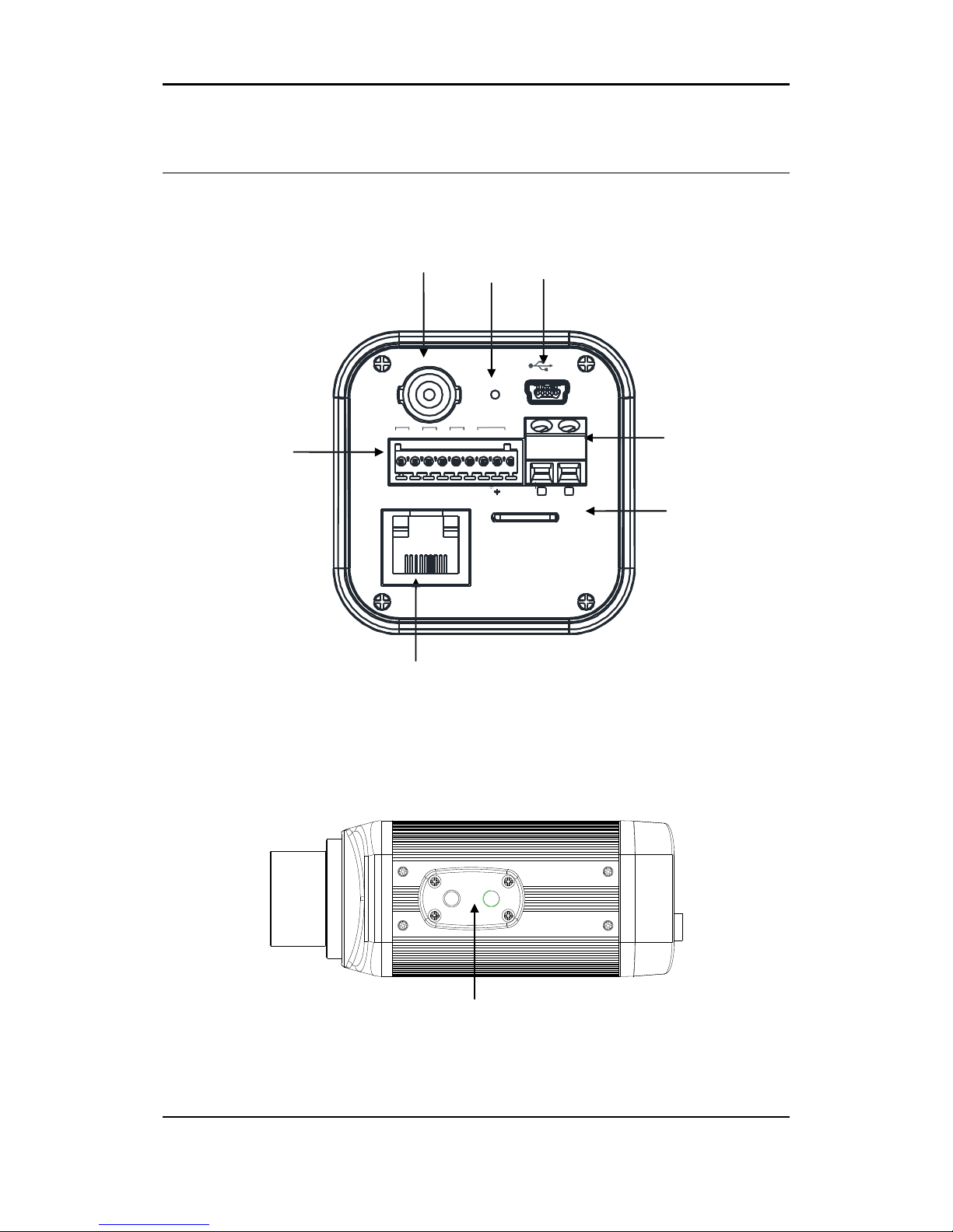
3.1. Rear View
3.2. Bottom View
⑥
⑤
③
①
②
④
⑦
ETHERNET
Micro SD
RESET
LOOP OUT
DC 12V
RS-485
DO DI AUDIO
_
+ C 1 C 1 Out In
⑧
Page 7
RTC Series RTC Installation Guide
01A.04 7
1 Analog video out
It is an analog video output port.
2 Reset
Reset switch is used for restarting or resetting the camera as Factory Default
(FD). Refer to the section “5.3.Reset” for more specific information.
3 USB connector
Insert a USB storage device
4 9 pin terminal block for D/I, D/O, audio, and serial communication
Refer to the section “4.1.Connectors” for more specific information.
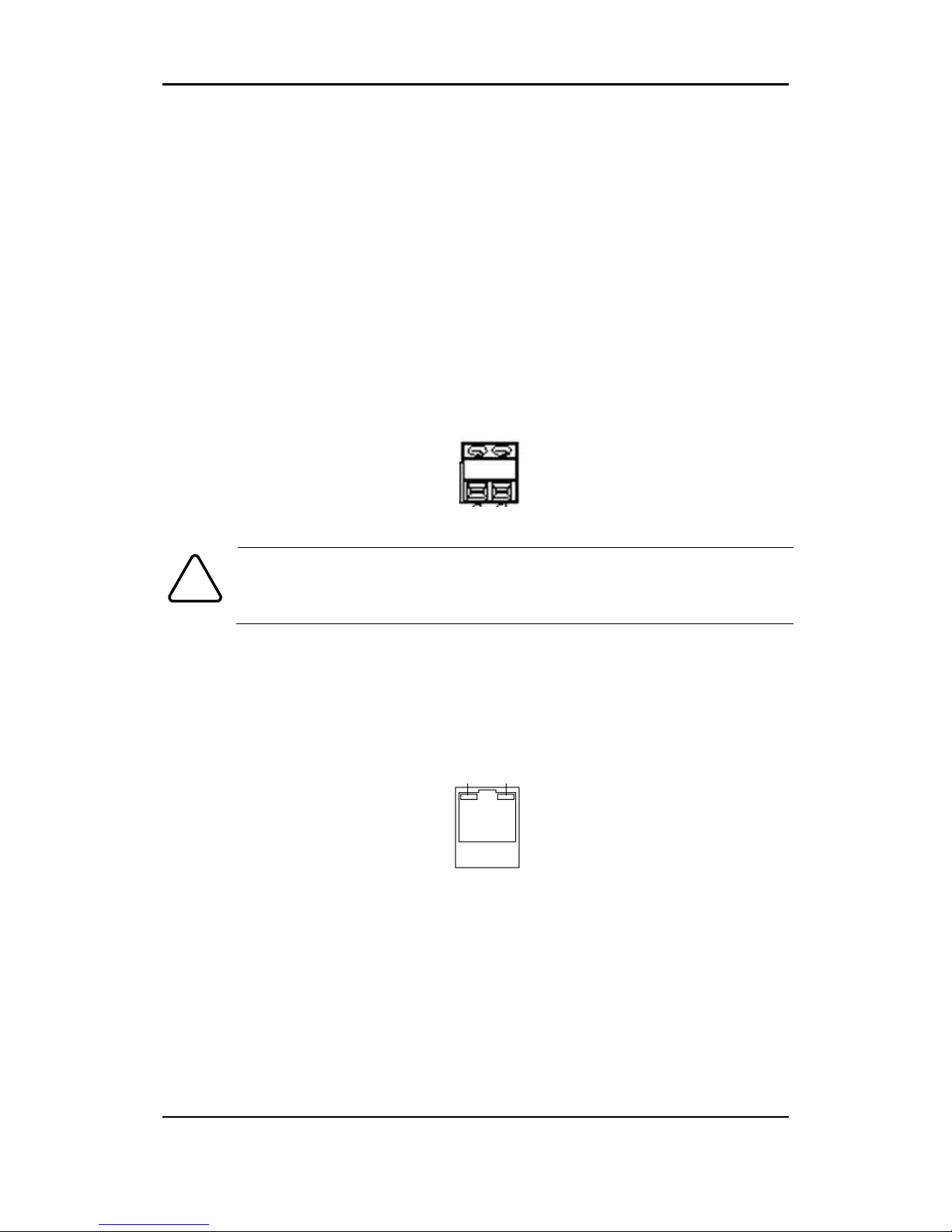
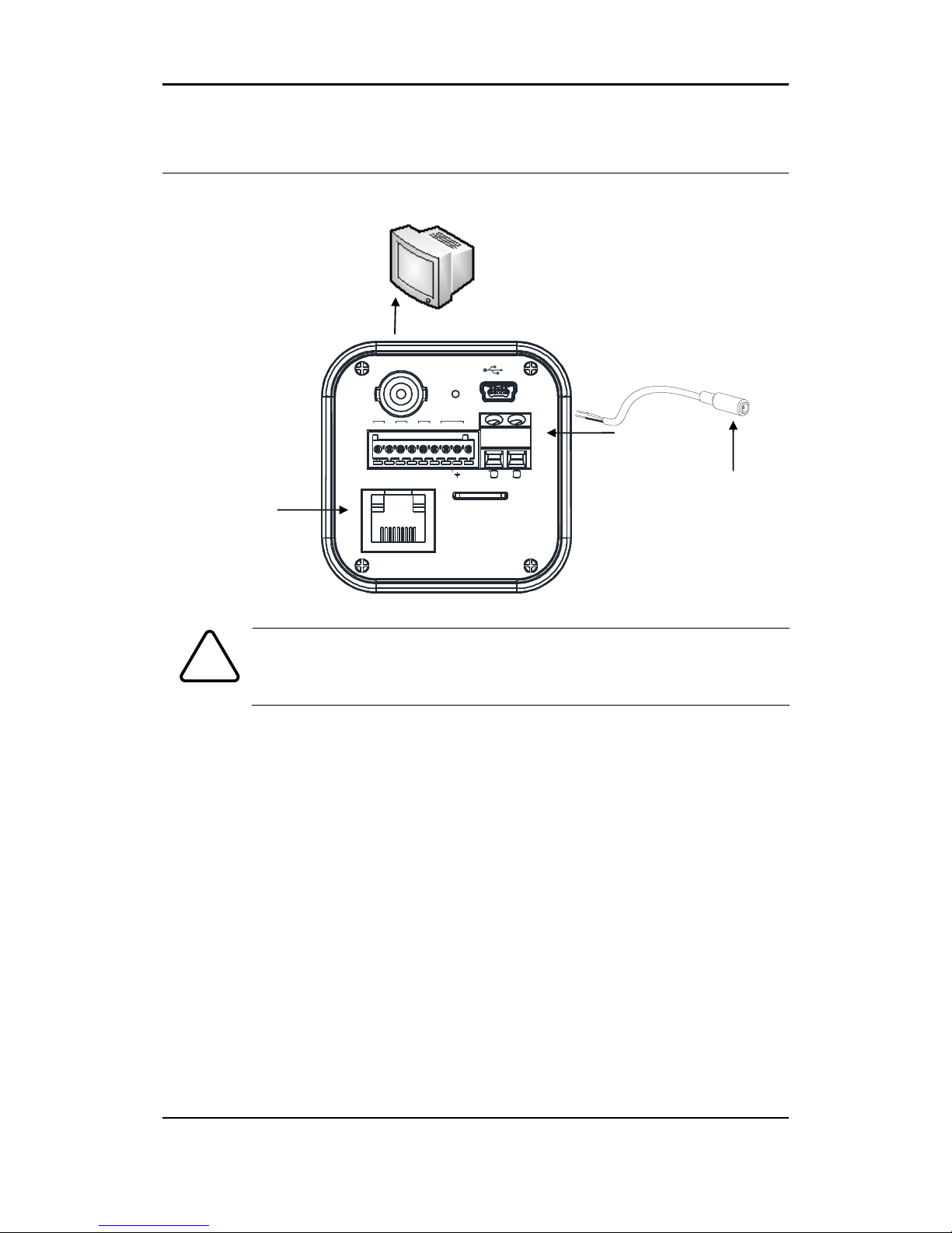
5 Power Adaptor Connector (DC 12V)
The camera needs a DC12V for power supply. Refer to the section “Power
Adapter Connector (DC 12V)” for more specific information.
The device is polarity sensitive. Incorrect power connection may cause
malfunction or damage to the IP device
6 Micro SD Card socket
It is a memory card slot for local storage.
7 LAN Connector (Ethernet)
This is a RJ45 LAN connector for 10/100 Base-T Ethernet.
When the device is powered on, the orange LED lights up first, and then the
green LED.
LED operation setting:
Both LEDs are off when the device is disconnected from a network. When it is
connected, the orange LED turns into solid light, whereas the green LED
continues to blink. To change the setting, refer to the section
4.5.12. LED
Setting
of the
NVC Web Page User’s Manual.
8 Adaptor for mounting the camera
Mounting adaptor is provided to mount the camera on a bracket or tripod.
Orange LED
Green LED
Caution
!
Page 8
RTC Series RTC Installation Guide
01A.04 8
4. CONNECTIONS
The device is polarity sensitive. Incorrect power connection may
cause the device to malfunction or damage the equipment.
Caution
!
DC Jack Adaptor
LAN Cable
Analog Video Out
ETHERNET
Micro SD
RESET
LOOP OUT
DC 12V
RS-485
DO DI AUDIO
_
+ C 1 C 1 Out In
Power Adaptor
Page 9
RTC Series RTC Installation Guide
01A.04 9
4.1.Connectors
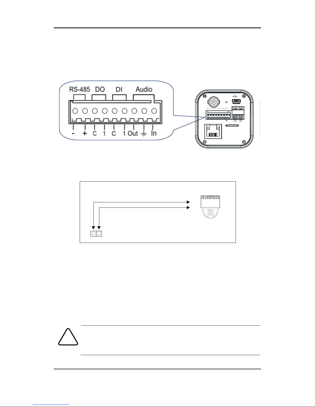
1 9 pin terminal block
2 RS-485
The RS-485 serial port consists of TRX+(RX+) and TRX-(RX-) as following the
following image.
RS-485 Connection
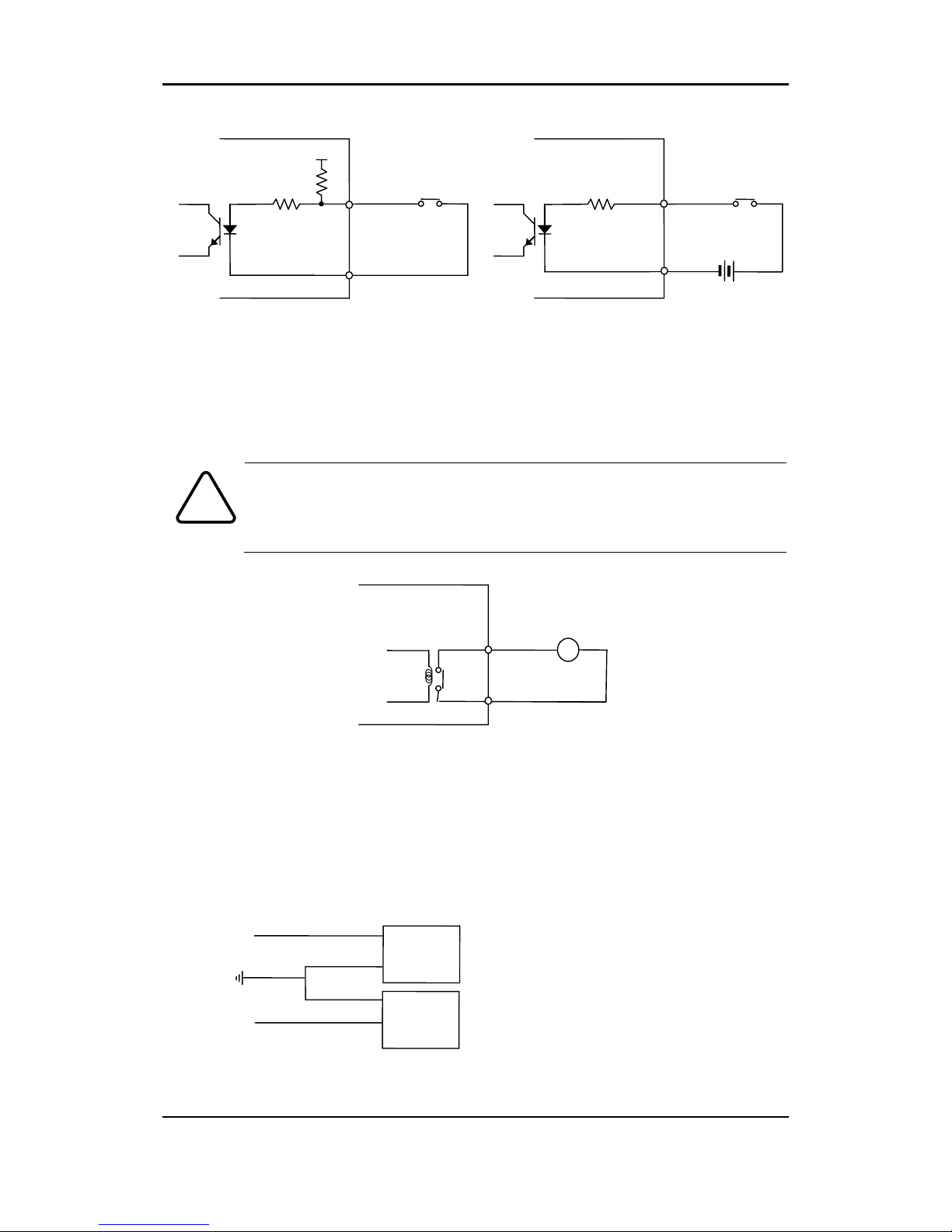
3 Sensor (DI) connection
The camera provides 1 channel D/I. It can be connected to either a voltage type
sensor or a relay type sensor as the following figures. It can be selected by
software.
Input voltage range: 0VDC minimum to 5VDC maximum, Max 50mA
Input voltage threshold: 1.5V
Do not exceed the maximum input voltage or relay rate.
Caution
!
TRX+(RX+)
<RS-485 Application>
+
-
TRX-(RX-)
TX+
TX-
PTZ Device
485 Devices
ETHERNET
Micro SD
RESET
LOOP OUT
DC 12V
RS-485
DO DI AUDIO
_
+ C 1 C 1 Out In
Page 10
RTC Series RTC Installation Guide
01A.04 10
4 Alarm (DO) connection
Only the relay type is supported.
Relay Rating: Max 24VDC 50mA
Do not exceed the maximum relay rating.
5 Audio connection
The camera has a mono audio input and a mono audio output. As the output
power for the audio is low, amplifier speaker is needed. (Do not use a headphone
or earphone directly to the camera.)
Caution
!
Mic
Ain
Speaker
Aout
DO
COM
Relay Type
Device
Internal
+5V
DI
COM
DI 1
COM + -
Relay Type
Voltage Type
+
-
Output of
Sensor
Output of
Sensor
Internal
Internal
+
-
Page 11
RTC Series RTC Installation Guide
01A.04 11
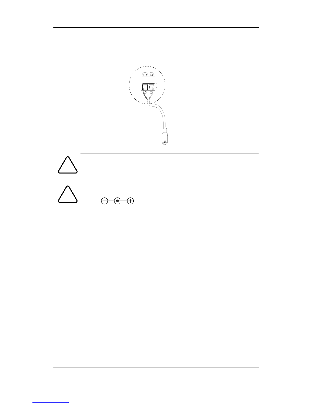
6 Power Adapter Connector (DC 12V)
Power adaptor connector connects to DC Jack adapter cable.
The device is polarity sensitive. Incorrect power connection may
cause the device to malfunction or damage the equipment.
Power Adaptor Connector (DC 12V)
Caution
!
Caution
!
RED + -
+
-
Page 12

RTC Series RTC Installation Guide
01A.04 12
5. CONFIGURATION
5.1.Set up network environment
The default IP address of the device is 192.168.XXX.XXX. Users can identify the
IP address of the device from converting the MAC address’s hexadecimal numbers,
which is attached to the device. Be sure that the device and PC are on a same
area network before running the installation.
5.1.1. Generic IP Environment
In case of generic private network environment where IP address
192.168.XXX.XXX are used, users may view the live streaming images on a web
page using the device’s default IP address:
1. Convert the device’s MAC address to the IP address. Refer to the Hexadecimal-
Decimal Conversion Chart at the end of the manual.
(The MAC address of the device is attached on the side or bottom of the
device.)
2. Start the Microsoft® Internet Explorer web browser and enter the address of
the device.
3. Web streaming and device configurations are supported through ActiveX
program. When the ActiveX installation window appears, authorize and install
the ActiveX.
Convert the last two set of hexadecimal numbers to decimal numbers.
Page 13
RTC Series RTC Installation Guide
01A.04 13
5.1.2. Custom IP Environment
IPAdminTool and the manual can download from www.rivatech.de homepage.
IPAdminTool is a management tool, which automatically scans all of the network
products for users to perform administrative tasks, which includes network
configurations, firmware update, device reboot, and device organizations.
To modify the device’s default IP address for customized network area;
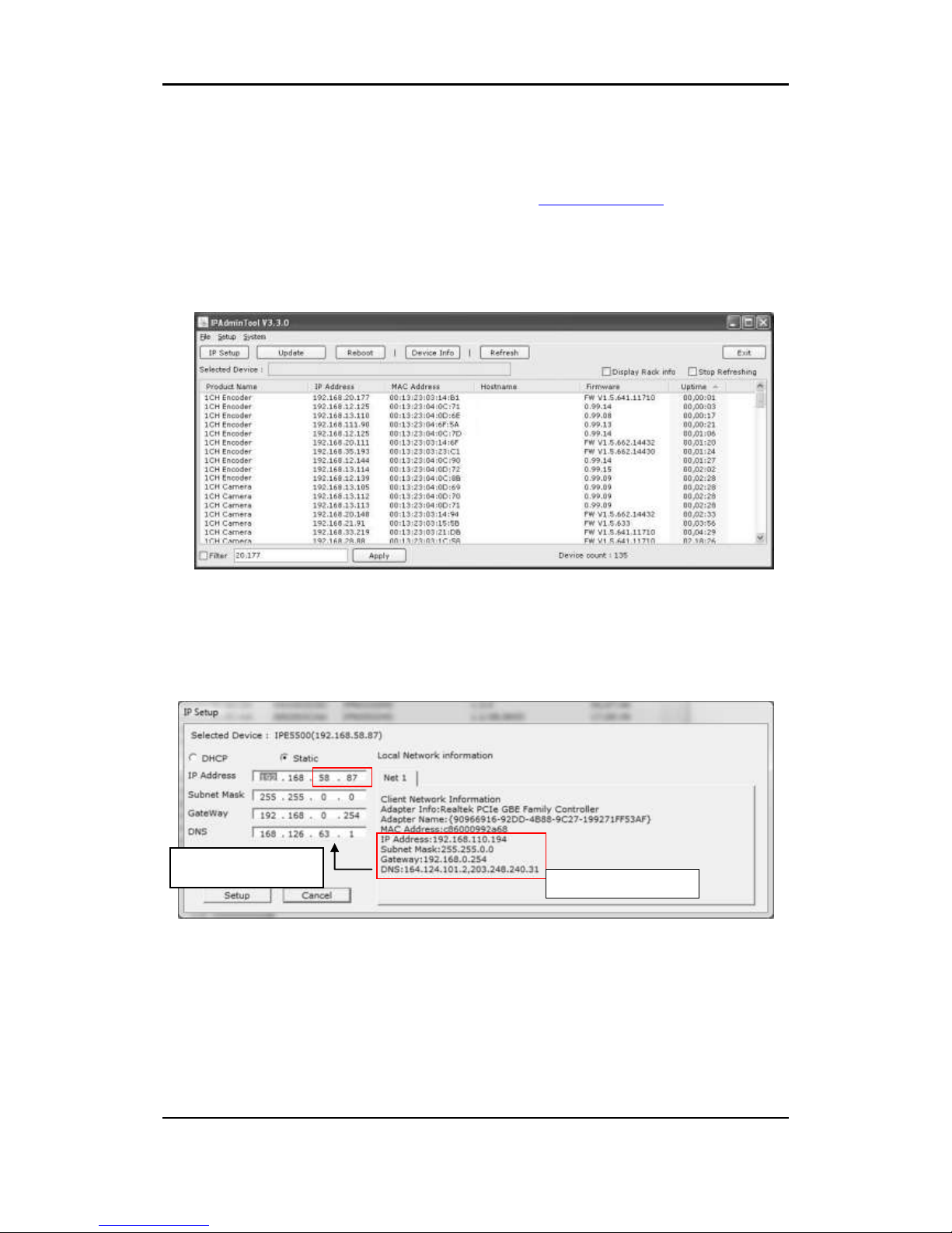
1.Find the device from the IPAdminTool’s list and highlight the device’s name.
2.Right-click the mouse and select “IP Address”; IP Setup window appears.
3.In the IP Setup’s window, information under ‘Local Network information’ displays
the user/PC’s network area information. Those information need to be
incorporated to the IP Address, Subnet Mask, Gateway, and DNS boxes, except
the last 2 sets of IP Address, which are to be the unique numbers for the device.
Refer to the image above for the setting
4. Click ‘Setup’ to complete the modification.
PC environment Info
Give new unique IP
address in last two sets
Page 14
RTC Series RTC Installation Guide
01A.04 14
5.2. View video on web page
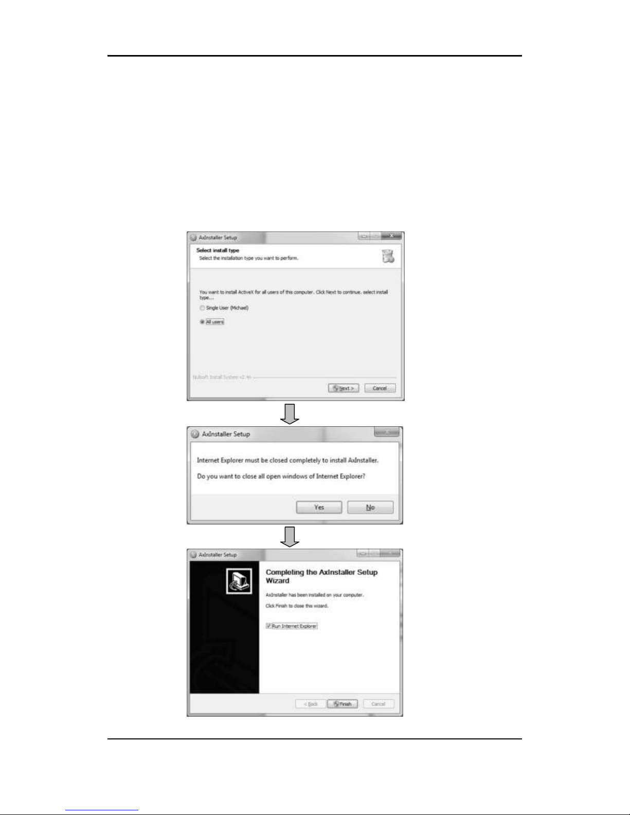
Once the device has the proper IP address, users can view the live streaming
images through a web browser. ActiveX needs to be installed in Microsoft
Internet Explorer.
1. Type the correct IP address in the Microsoft® Internet Explorer
2. Grant the web browser’s AxAll.cab ActiveX setup and proceed with
installations.
Page 15
RTC Series RTC Installation Guide
01A.04 15
Caution
!
Caution
!
3. Follow the instructions of the dialog boxes and complete the installation. Once
the installation is complete, start the web browser again and check if video
stream is displayed in the main view frame.
If “
This software requires the Microsoft XML Parser V6 or higher.
Please download MSXML6 from the Microsoft website to continue.
Error code: Cannot create XMLDOMDocument.
” message appears,
download and install the Microsoft Core XML Services (MSXML)
6.0.
5.2.1. View video using IPAdmin Tool
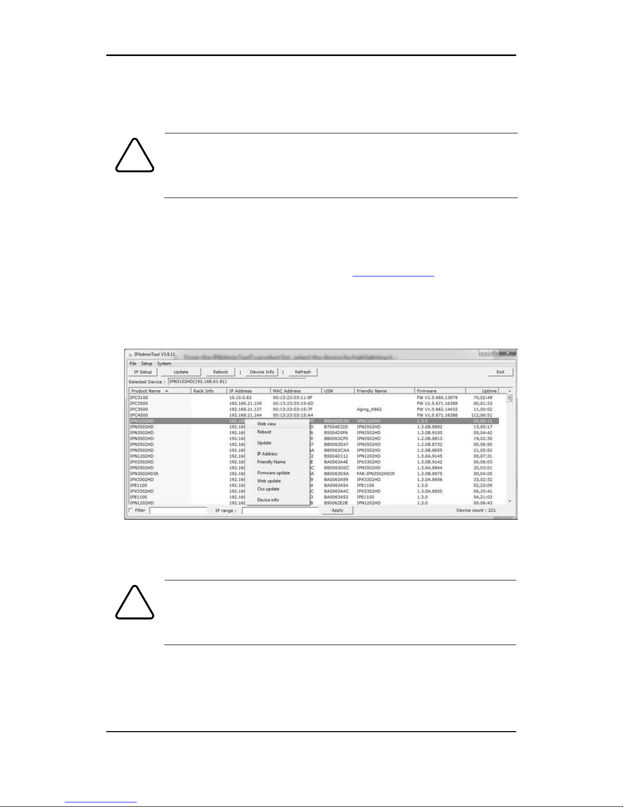
IPAdminTool automatically searches all activated network encoders and IP
cameras and shows the product name, IP address, MAC address and etc.
IPAdminTool and the manual can download from www.rivatech.de homepage.
1. From the IPAdminTool’s product list, select the device by highlighting it.
2. Right-click the mouse and select web-view
3. The system’s default web browser opens the device’s address.
Whether directly accessing the streaming video through typing IP
address on a web page or taking steps through IPAdminTool, the
ActiveX is needed to be installed for the Microsoft® Internet
Explorer to have the complete configuration privileges.
Page 16

RTC Series RTC Installation Guide
01A.04 16
5.3. Reset
Reset can be carried out as follows:
1. Use a pointed object to push the reset button for 1~2 seconds.
2. Wait for the system to reboot.
5.4. Factory Default
Resetting the device to the factory default will reset all configured parameters to
the initial factory settings. To perform the Factory Default settings:
1. Use a pointed object to push the reset button and hold for 5 seconds. The
orange LED turns off while green LED flashes.
2. Once the green LED becomes solid, release the reset button.
3. Wait for the system to reboot.
The factory default settings are:
IP address: 192.168.xx.yy
Network mask: 255.255.0.0
Gateway: 192.168.0.1
User ID: root
Password: pass
Page 17

RTC Series RTC Installation Guide
01A.04 17
APPENDIX (A): SPECIFICATIONS
Summary
Camera Module
Camera
Module
Focal
Plane
Array
17 ㎛ Next Generation Mirobolometer Technology
Effective
Pixels
320(H)x240(V)
Scanning
system
Progressive Scan
Spectral
Reponse
8~14 ㎛
Lens
(optional)
7.5mm, F1.4 (42.1 Degree FoV)
16.7mm, F1.2 (18.7 Degree FoV)
25mm, F1.2 (12.4 Degree FoV)
35mm, F1.2 (8,9 Degree FoV)
50mm, F1.2 (6.2 Degree FOV)
Other Lenses available upon request
NEDT
Less than 50mK
Electrical Characteristics
Analog Video Output
1Vp-p, 75Ω
Audio Input
Linein, 1.43Vp-p(Min 1.35Vp-p, max 1.49 Vp-p), 39
KΩ
Audio Output
Lineout, 46mW Power, 16 Ω
Sensor(D/I)
Max 50mA@5VDC, TTL level 1.5V threshold
Alarm(D/O)
Max 50mA@24VDC
On-state resistance: 50 Ω (max continuous)
Power Source
DC 12V / PoE IEEE802.3af(class 0)
Power Consumption
(Approx.)
6~8W(DC 12V)
Video
Compression Format
H.264, MPEG-4, MJPEG Selectable per Stream
Number of Streams
Dual Stream, Configurable
Resolution
Sensor is 320x240, Image can be scaled from QCIF to
D1
Compression FPS
9Hz or 30Hz Models Available
Motion Detection
Supported (DSP)
Burnt-in Text (Digital)
Supported (DSP)
Output
1 Loop Out (BNC connector)
Audio
Page 18

RTC Series RTC Installation Guide
01A.04 18
Input / Output
1/1 channel
Compression Format
G.711
Function
Digital Input / Ouput
1/1 channel
RS-485
Supported
Network
10/100 Base-T
Protocol
TCP/IP, UDP/IP, HTTP, RTSP, RTCP, RTP/UDP,
RTP/TCP,
SNTP, mDNS, UPnP, SMTP, SOCK, IGMP, DHCP,
FTP, DDNS, SSL v2/v3, IEEE 802.1X, SSH, SNMP
v2/v3
USB 2.0
Supported (Mini-B plug)
SD Slot
Supported (Micro SD)
※ Micro SD Card not included
Environment Condition
Operating
Temperature (indoor)
0 ˚C ~ 50 ˚C (32˚F ~ 122 ˚F)
Operating
Temperature (outdoor)
ODE-1000T-PoE: -20 ~ 50℃
ODE-1000T-230: -40 ~ 50℃
*Cold start: 0 ˚C
Operating Humidity
Up to 85% RH
Mechanical Condition
Material
Aluminum Die Casting-2
Color
Grey
Dimension
65(W) x 65(H) x 114.2(D) mm
Weight (Approx.)
300 g
Page 19
RTC Series RTC Installation Guide
01A.04 19
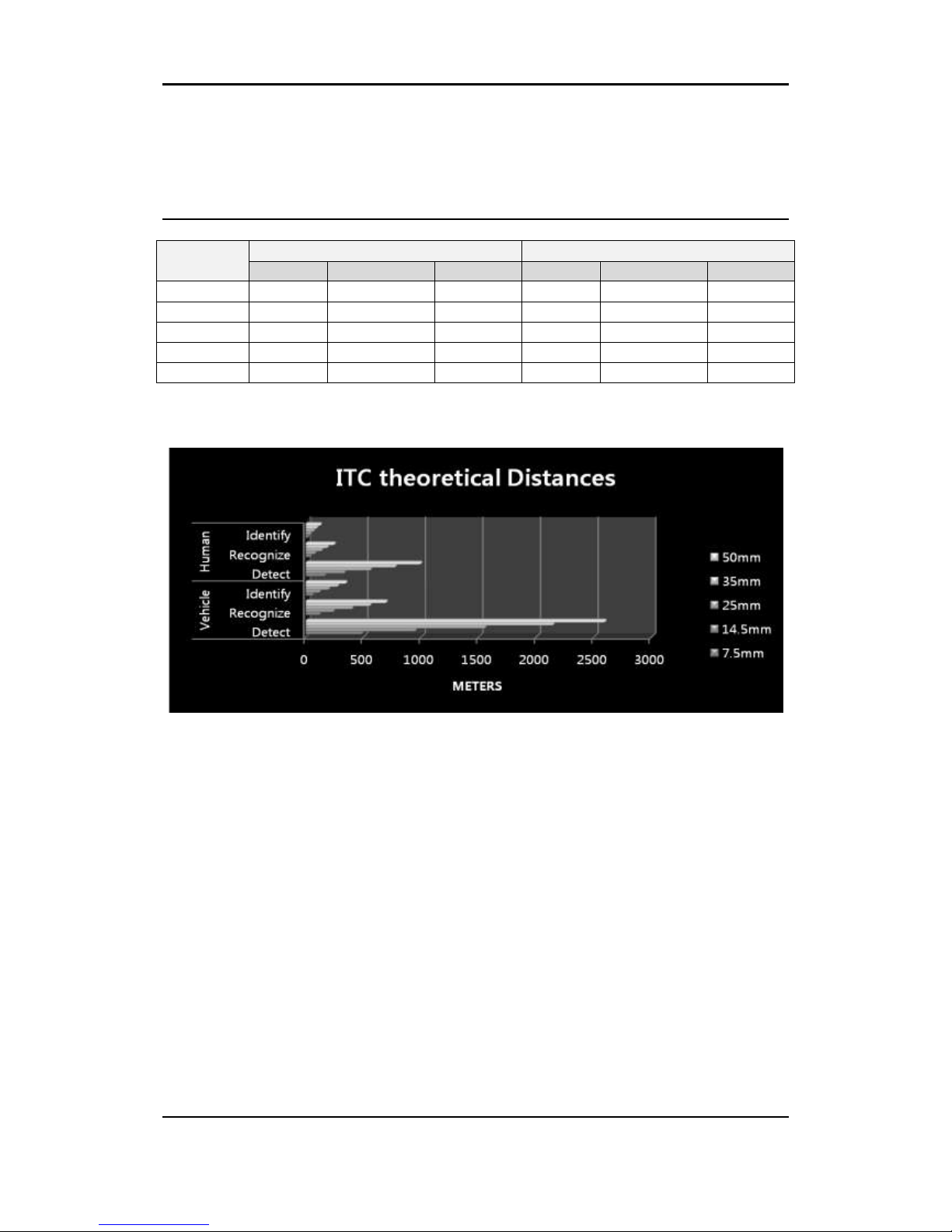
APPENDIX (B): THEORATICAL
DISTANCE
Lens
Vehicle
Human
Detect
Recognize
Identify
Detect
Recognize
Identify
7.5mm
491
125
62
170
43
22
14.5mm
955
243
122
338
84
42
25mm
1560
405
202
565
140
70
35mm
2150
560
280
780
190
97
50mm
2600
700
350
1000
250
128
Unit: meter
Please Note!: Released distance are based on theoretical calculation. In practical
application reached distance can diverse depending environment conditions.
Page 20

RTC Series RTC Installation Guide
01A.04 20
APPENDIX (C): POWER OVER
ETHERNET
The Power over Ethernet (PoE) is designed to extract power from a conventional
twisted pair Category 5 Ethernet cable, conforming to the IEEE 802.3af Powerover-Ethernet (PoE) standard.
IEEE 802.3af allows for two power options for Category 5 cables.
The IEEE 802.3af-2003 standard allows up to 15.4 W power to device.
However, 12.95W is the maximum available power, as some power gets lost in
the cable.
PoE has advantages over conventional power in such places where AC powers
cannot be reached or expensive to wire.
Note: For proper activation of 12V PoE, the Category 5 cable must be shorter
than 140m and conform the PoE standard.
PoE compatibility
With non-Power Sourcing Equipment (PSE)
When it is connected with non-PSE, the power adaptor should be used.
With power adaptor
Connecting both PSE and power adaptor do not cause any harms to the
products. Disconnecting power adaptor while it is operating does not stop
operation. The product continues to work without rebooting.
Power classification
The PoE Power Class supported by the IP device is Class 0.
Class
Usage
Minimum Power Levels
Output at the PSE
Maximum Power Levels
at the Powered Device
0
Default
15.4W
0.44 to 12.95W
Page 21
RTC Series RTC Installation Guide
01A.04 21
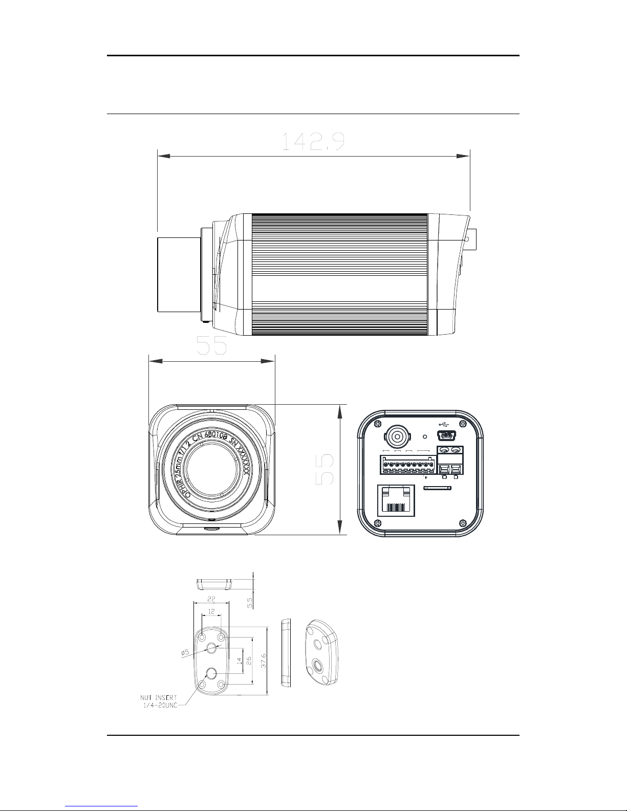
APPENDIX (D): DIMENSIONS
Rear view
ETHERNET
Micro SD
RESET
LOOP OUT
DC 12V
RS-485
DO DI AUDIO
_
+ C 1 C 1 Out In
Page 22
RTC Series RTC Installation Guide
01A.04 22
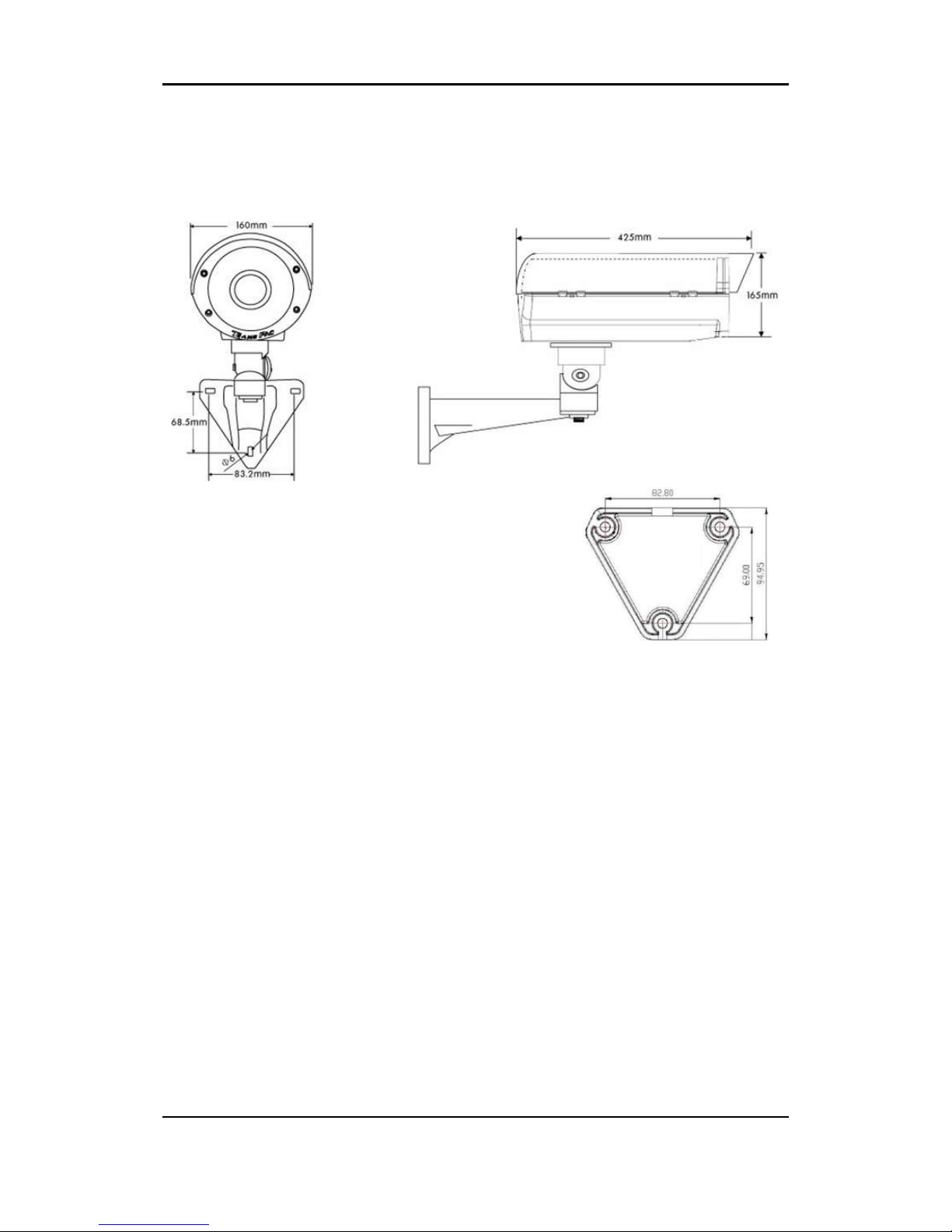
Housing Model
UNIT: mm
Page 23

RTC Series RTC Installation Guide
01A.04 23
APPENDIX [E]: CAMERA HOUSING
The housing protects the surveillance device from material weathering,
intentional vandalizing, and miscellaneous environmental impacts. This
weatherproof IP66 housing has heater and fan attached inside, which are
controlled by the sensor.
Housing Overview
Models
ODE-1000T-PoE, ODE-1000T-230
Material
Aluminum die casting
Color
Ivory
Paint
Powder coating
Size (mm)
160(W) x 165(H) x 425(D)mm
Weight
5Kg
Heater/Fan Control
Heater: 0 (ON) / 10 (OFF)
Fan: 35℃ (ON) / 25℃ (OFF)
Operating
Temperature.
ODE-1000T-PoE: -20 ~ 50℃
ODE-1000T-230: -40 ~ 50℃
Input power
ODE-1000T-PoE: PoE+, 50/60Hz
ODE-1000T-230: AC90V ~ 230V, 50/60Hz
Protection
IP66
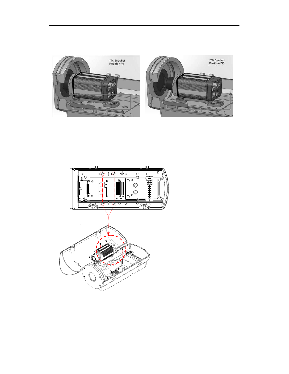
Positioning of Camera Mount by Lens
LENS
Mount Position
Bracket Position
7.5mm A 1
16.7mm A 1
25mm B 1
35mm A 2
50mm C 2
Page 24
RTC Series RTC Installation Guide
01A.04 24
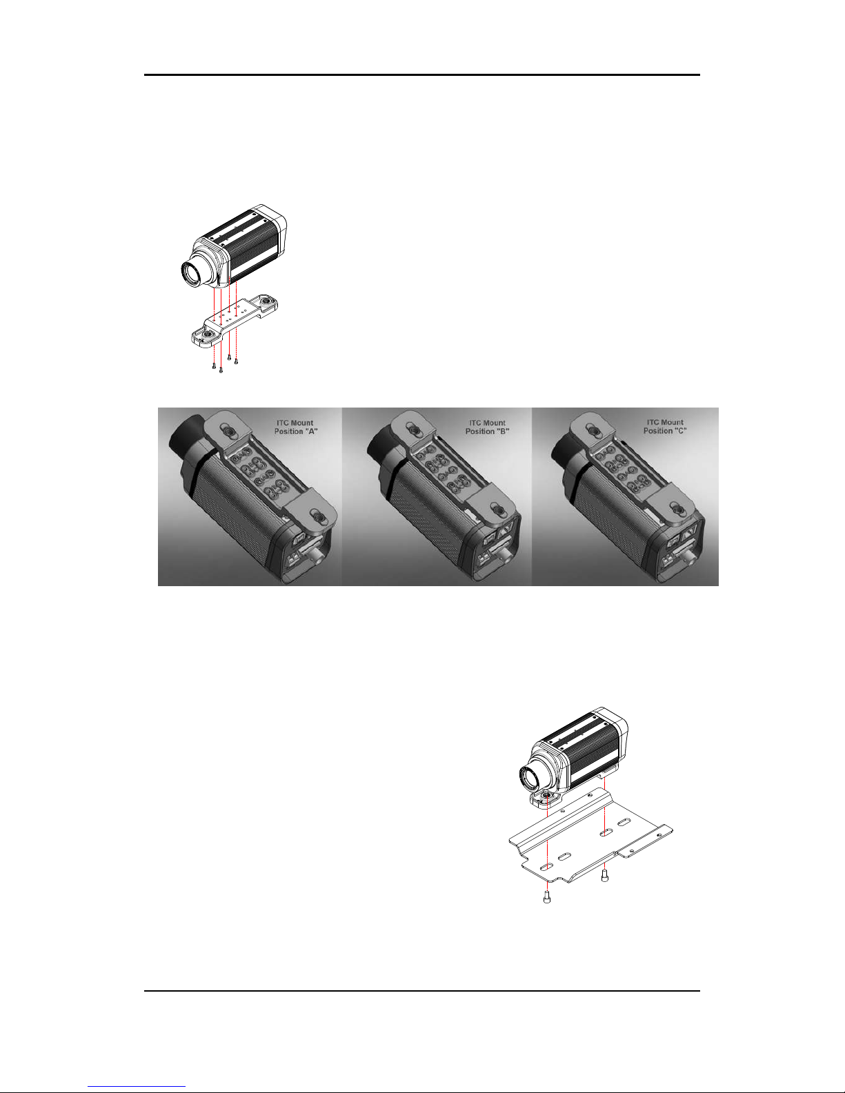
Camera Installation
2. Fix the camera mount on the
mount plate.
1. Attach the camera mount on the
bottom of the camera.
*The camera mount can be attached on the camera at three different locations (A, B and
C). Consider the lens length before determining the camera mount screw holes’ location.
Page 25
RTC Series RTC Installation Guide
01A.04 25
*The camera mount can be fixed at two different locations on the mount plate (1 and 2).
Consider the lens length before determining the mount plate screw holes’ location.
3. Fix the mount plate in the
housing.
Camera & Camera mount조립
Outdoor housing 조립
Camera mount plate 조립
Page 26
RTC Series RTC Installation Guide
01A.04 26
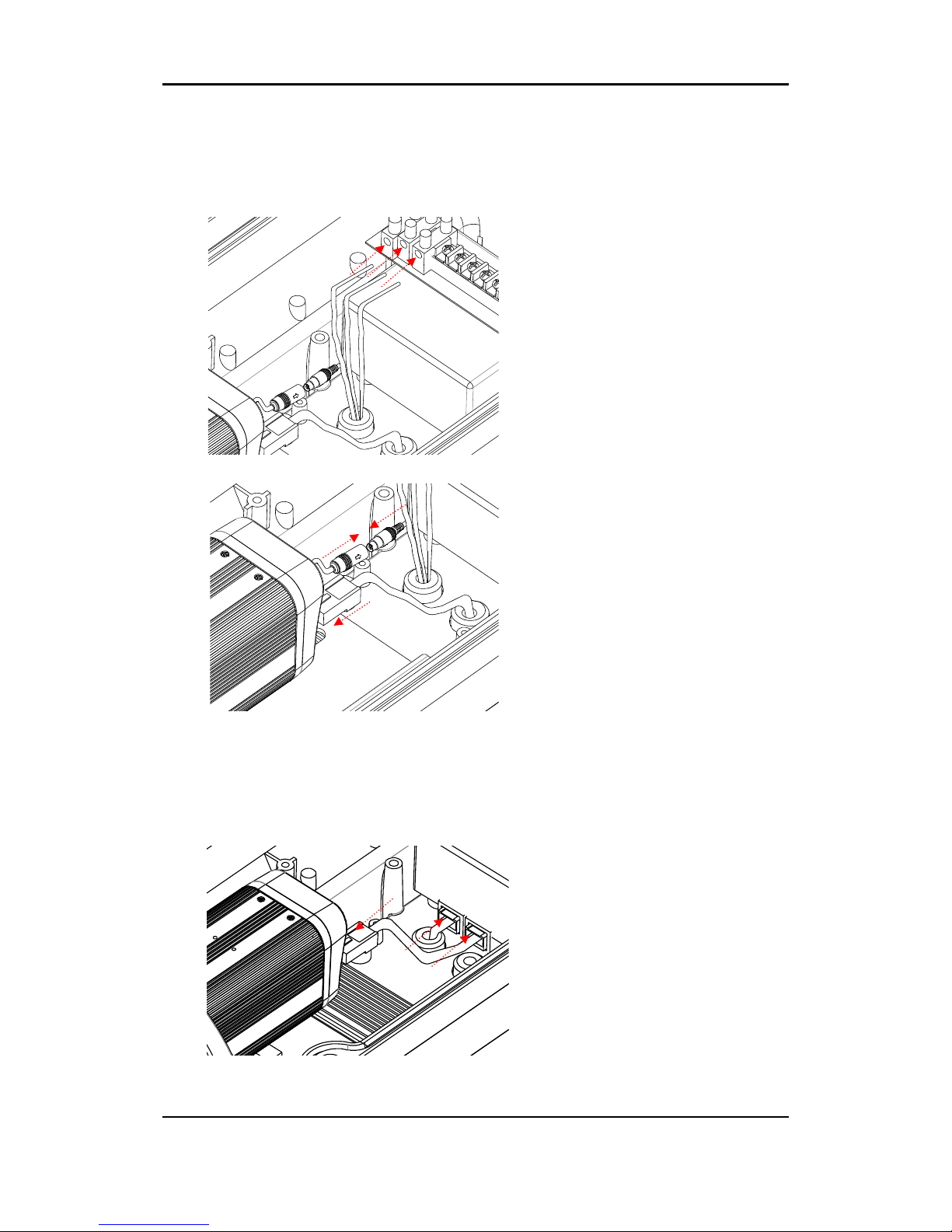
5. Connect power source to the
camera and also a LAN cable.
ODE-1000T_230 / 024
전원연결
4. Connect LAN cable into the
internal power unit. And make sure
the high power PoE(PoE+) is used for
this installation.
5. Connect LAN cable to the camera.
4. Connect power source into the
terminal, located inside of the
housing. Make sure all cables are
correctly-connected to its
corresponding end. (+, - and
ground)
( ODE-1000T-230)
(ODE-1000T-PoE)
Page 27
RTC Series RTC Installation Guide
01A.04 27
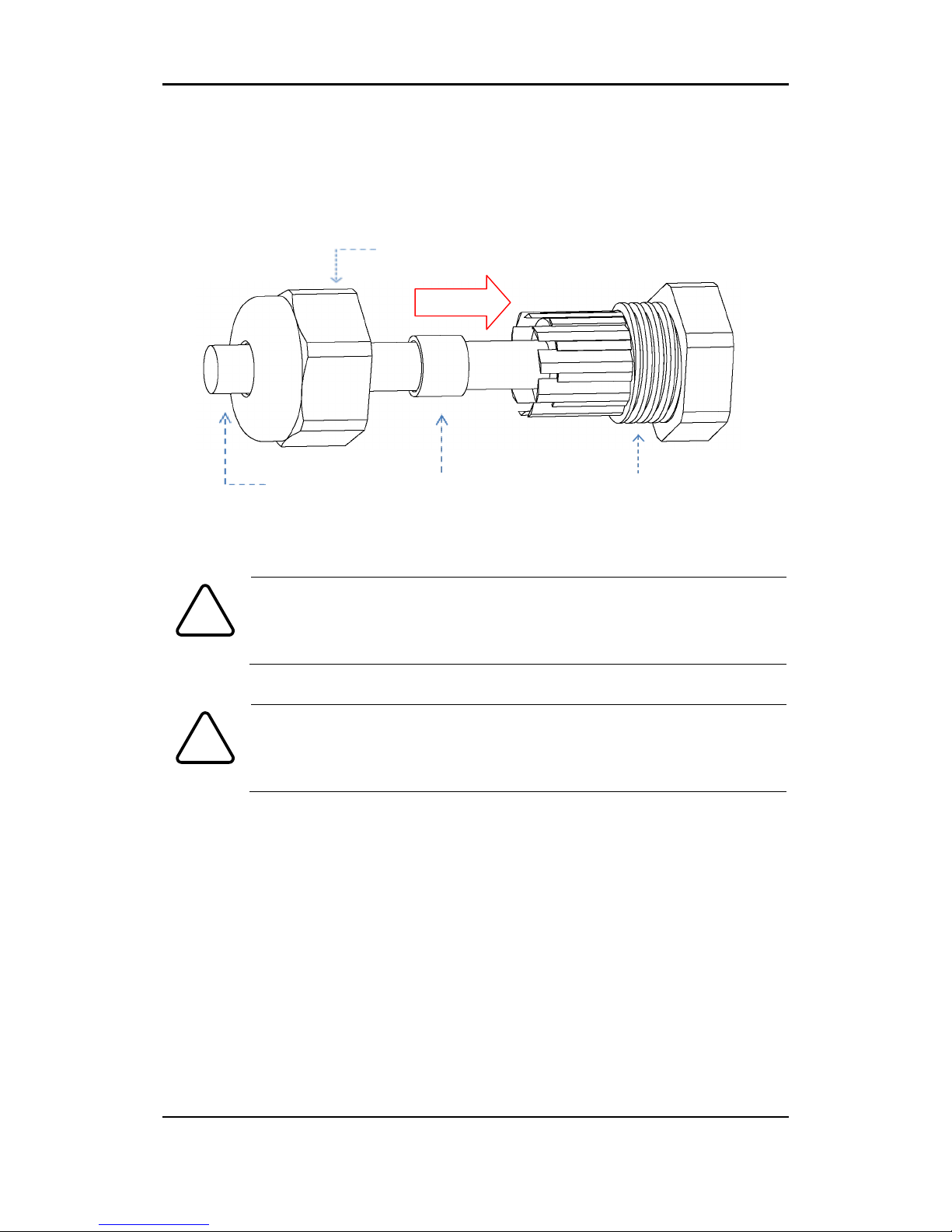
To connect cables
The bottom of the housing has two cable glands for cables. Use control cable to
connect with the cable gland (Refer to the below figure)
Be advised to connect the surveillance camera with designated
power voltage. Connecting the camera directly to 120V/220V cable
will damage the device.
Make sure there’s no empty space when capping the cable gland.
Using a rubber packing ring to remove any empty the space between
the cap and inner cable gland will most likely prevent water pervading
into the housing’s internal parts.
Caution
!
Caution
!
Control Cable
Rubber Packing Ring
Cable Gland
Cap
Page 28

RTC Series RTC Installation Guide
01A.04 28
APPENDIX (F): HEXADECIMALDECIMAL CONVERSION TABLE
Refer to the following table when you convert the MAC address of your device to
IP address.
Page 29

RTC Series RTC Installation Guide
01A.04 29
Hex
Dec
00 0 01 1 02 2 03 3 04 4 05 5 06 6 07 7 08 8 09
9
0A
10
0B
11
0C
12
0D
13
0E
14
0F
15
10
16
11
17
12
18
13
19
14
20
15
21
16
22
17
23
18
24
19
25
1A
26
1B
27
1C
28
1D
29
1E
30
1F
31
20
32
21
33
22
34
23
35
24
36
Hex
Dec
25
37
26
38
27
39
28
40
29
41
2A
42
2B
43
2C
44
2D
45
2E
46
2F
47
30
48
31
49
32
50
33
51
34
52
35
53
36
54
37
55
38
56
39
57
3A
58
3B
59
3C
60
3D
61
3E
62
3F
63
40
64
41
65
42
66
43
67
44
68
45
69
46
70
47
71
48
72
49
73
Hex
Dec
4A
74
4B
75
4C
76
4D
77
4E
78
4F
79
50
80
51
81
52
82
53
83
54
84
55
85
56
86
57
87
58
88
59
89
5A
90
5B
91
5C
92
5D
93
5E
94
5F
95
60
96
61
97
62
98
63
99
64
100
65
101
66
102
67
103
68
104
69
105
6A
106
6B
107
6C
108
6D
109
6E
110
Hex
Dec
6F
111
70
112
71
113
72
114
73
115
74
116
75
117
76
118
77
119
78
120
79
121
7A
122
7B
123
7C
124
7D
125
7E
126
7F
127
80
128
81
129
82
130
83
131
84
132
85
133
86
134
87
135
88
136
89
137
8A
138
8B
139
8C
140
8D
141
8E
142
8F
143
90
144
91
145
92
146
93
147
Hex
Dec
94
148
95
149
96
150
97
151
98
152
99
153
9A
154
9B
155
9C
156
9D
157
9E
158
9F
159
A0
160
A1
161
A2
162
A3
163
A4
164
A5
165
A6
166
A7
167
A8
168
A9
169
AA
170
AB
171
AC
172
AD
173
AE
174
AF
175
B0
176
B1
177
B2
178
B3
179
B4
180
B5
181
B6
182
B7
183
B8
184
Hex
Dec
B9
185
BA
186
BB
187
BC
188
BD
189
BE
190
BF
191
C0
192
C1
193
C2
194
C3
195
C4
196
C5
197
C6
198
C7
199
C8
200
C9
201
CA
202
CB
203
CC
204
CD
205
CE
206
CF
207
D0
208
D1
209
D2
210
D3
211
D4
212
D5
213
D6
214
D7
215
D8
216
D9
217
DA
218
DB
219
DC
220
DD
221
Hex
Dec
DE
222
DF
223
E0
224
E1
225
E2
226
E3
227
E4
228
E5
229
E6
230
E7
231
E8
232
E9
233
EA
234
EB
235
EC
236
ED
237
EE
238
EF
239
F0
240
F1
241
F2
242
F3
243
F4
244
F5
245
F6
246
F7
247
F8
248
F9
249
FA
250
FB
251
FC
252
FD
253
FE
254
FF
255
Page 30

RTC Series RTC Installation Guide
01A.04 30
REVISION HISTORY
MAN#
DATE(M/D/Y
)
Comments
01A.00
04/30/201
2
Created.
01A.01
05/24/201
2
Housing appendix added
01A.02
06/25/201
2
DI/DO specification corrected
01A.03
09/18/201
2
Hyperlink and chapter update. Housing Spec update
 Loading...