

Page 1
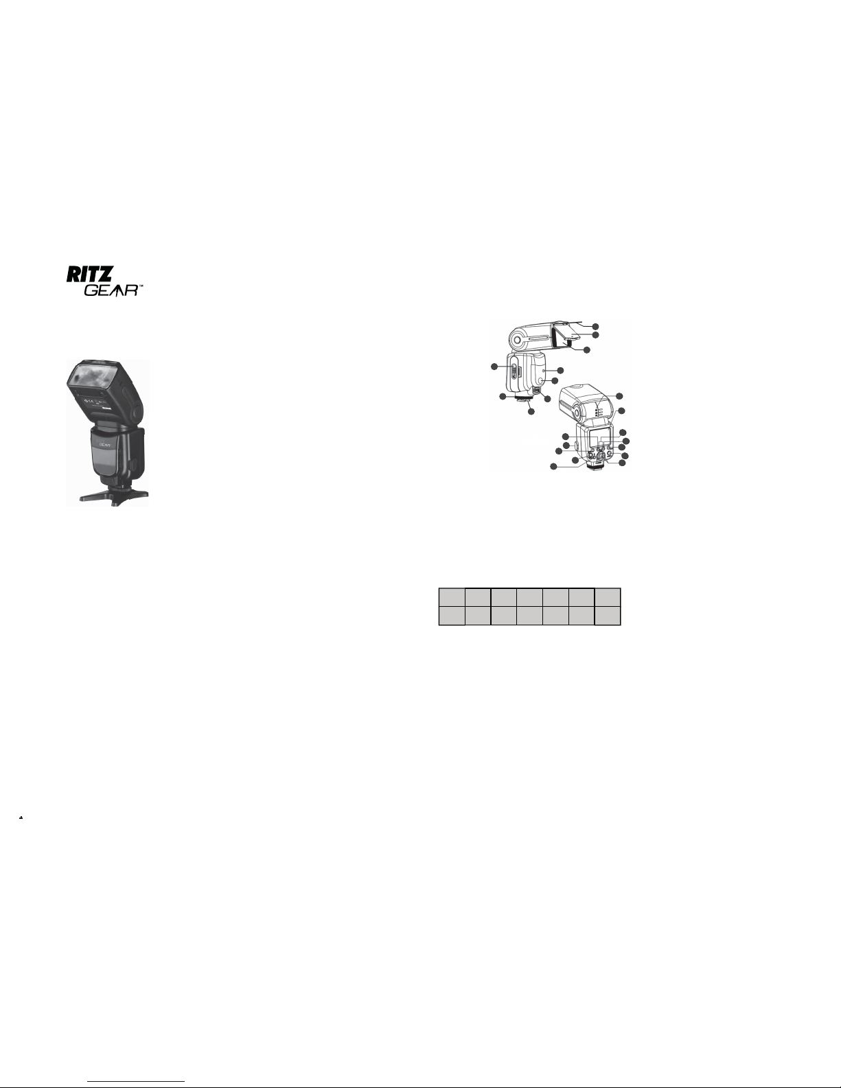
Figure 1
1
3
4
5
6
7
8
9
10
11
12
13
14
15
16
17
18
19
20
21
2
2 IDENTIFICATION OF PARTS
(Figure 1)
1. Battery Cover
2. Locking Wheel
3. Hot-Shoe
4. External Power Jack
5. Focusing Light
6. Flash Sensor
7. Flash Head Lens
8. Diffusion Screen
9. Bounce Card
10. Tilt Angle Scale
11. Display Screen
12. Clear Buttons (both pressed)
13. Right Clear Button
14. Zoom Button/Wireless Settings
15. On-Off Button
16. Keypad
17. Flash Test/Charge Light Button
18. Mode Button
19. Back-light/Function Button
20. PC Jack
21. Wireless Select Button
1 INTRODUCTION
Thank you for your purchase of this Ritz Gear high-performance,
feature-packed flashgun. It’s like a flashgun of yesteryear on steroids.
It looks like an ordinary camera-mounted flash, but the
enhancements built in to this light source make it anything
but ordinary.
This flash features a built-in diffusion screen and white bounce card.
It operates with through-the-lens cameras or cameras equipped with
PC synchronization. It can also serve as a wireless master or slave
when using multiple flash units. In addition, it provides eight power
levels of light and can be set to keep up with rapid fire exposures
of eight frames per second.
Before operating the flash, please read all of the following instructions
and keep them in a safe place for future reference.
Safety Precautions
1 Be sure batteries are inserted correctly. Refer to Section 3
Battery Installation.
2 The flashgun is to remain dry at all times; do not use the flashgun in
the rain; store it in a non-humid environment and do not spray or
pour liquid cleaners onto the flashgun.
3 When necessary, wipe the exterior with a clean, soft, dry cloth. If
some dirt or stain can’t be removed with a dry cloth, apply a small
amount of water or liquid cleaner to the cleaning cloth and rub the
surface clean.
4 Do not fire the flash into a person’s eyes if the flash is closer than
three feet from the person.
5 Do not attempt to disassemble or otherwise repair the flashgun.
Extremely high voltage is used to ignite the flash tube, and that
voltage may remain in a charged capacitor.
6 Keep the flashgun away from small children.
7 As batteries age, they are susceptible to leaking their chemicals
and corroding battery terminals.
If the flashgun is not to be used for a month or more, remove
the batteries.
3 BATTERY INSTALLATION
1 Slide the battery compartment cover down in the direction of the
small arrow.
2 Flip the door up 90°.
3 Insert 4 x AA alkaline batteries following the polarity markings
stamped into the metal contacts on the inside of the door.
NOTE: The most economical battery to use is a size AA (1.5-volts)
marked “alkaline.” Priced slightly higher is size AA (1.5-volts)
“lithium.” A third choice is size AA “nickel metal-hydride” which
provides only 1.2-volts. They lose their charge sooner than the
previous two types, but they are rechargeable.
An alternative to batteries is to use an external power adapter (not
included) which plugs into the power receptacle located on the
bottom-front of the flashgun. It will provide the fastest recycle
times, but requires a 120-volt cord between a wall outlet and
the flashgun.
4 From top to bottom, the positive terminal should be facing out,
then a negative terminal, then positive, and negative facing out in
the last position.
5 Close the Battery Compartment Cover, Item 1 to compress the
batteries then slide it up until it locks in place.
NOTE: It is recommended that the flashgun be in its OFF position
when inserting or removing batteries.
4 MOUNT THE FLASHGUN ON YOUR CAMERA
1 Loosen the Locking Wheel, Item 2 at the bottom of the flashgun
and turn it so it’s as far as possible above its Hot-Shoe, Item 3.
2 Slide the flashgun all the way into the camera’s hot-shoe mount.
3 To secure the flashgun in place, turn the Locking Wheel, Item 2
downward until it’s tight against the camera’s hot-shoe.
5 Use the chart below to help you select the number of times you
can fire the flash during a single exposure.
6 Since the frequency is already set at 8-Hz, we’ll continue with this
example: let’s program 1/8 power and two flashes per exposure.
7 Press the center button of the Keypad Button, Item 16 repeatedly
until the frequency begins flashing (already set to 8-Hz) then press
the center button of the Keypad Button, Item 16 to set the next
column blinking.
8 Use the left and right buttons of the Keypad Button, Item 16 to set
the number of flashes to “2” then press the center button again to
flash the power output level.
9 Use the left and right buttons to set the power level to “1/8” then
press the center button to store all three numbers.
10 Press and hold the Flash Test Button, Item 17 and the video head
will flash twice and stop, verifying you’ll get two flashes during a
single exposure.
8 E-TTL MODE OPERATION
1 Press the On/Off Button, Item 15 for 3-sec to turn on the flashgun.
2 Press the Mode Button, Item 18 repeatedly until “E-TTL” is
displayed on the top line of the screen.
3 The flashgun is ready to go, taking all its commands and settings
from the camera. Just point and shoot.
4 If the flash exposure is a bit too bright or too dark, you can make
fine-tuned adjustments to the exposure value (EV) by pressing the
left and right buttons on the Keypad Button, Item 16. There are 9
values below zero and 9 values above zero (-3.0 to +3.0).
For a Nikon camera, press its “FV” button. (Refer to your camera
manufacturer’s instruction booklet for detailed procedures regarding
the locking of the flash to a particular object in the scene.)
6 MANUAL MODE OPERATION
Use this mode to control every feature of the flash.
1 Press the Mode Button, Item 18 until the “M” appears on the top
line of the display.
2 Decide what percent age of the flash’s light you want to use on the
subject. There are eight possible values which appear on the second
line of the display and range between full power (1/1) to the least
power (1/128).
3 To choose a power level, press the left or right button in the Keypad
Button, Item 16.
4 Once a value is selected, it can be fine tuned even further by
choosing an exposure value (EV) for the power level. Choices
include: 0EV, +.3EV, +.7EV and in the opposite direction: 0EV, -.3EV
and -7EV.
7 MULTI MODE (STROBOSCOPIC)
Use this mode to spray a moving subject, such as a golf swing, with
rapid short-burst pulses of light to capture the subject in up to eight
successive positions on one frame.
1 Press the Mode Button, Item 18 successively until the word “Multi”
appears on the top line of the display.
2 Next, set the frequency of the flash (the number of times per
second that the light will flash during each firing of the light) by
pressing the center button of the Keypad Button, Item 16.
3 The frequency in hertz (Hz) will begin flashing. At this time, press
the left or right buttons of the Keypad Button, Item 16 to set the
time between flashes. For now, set the frequency to 8Hz.
4 Press the center button of the Keypad Button, Item 16 to store the
number and begin the blinking of the number of times the unit will
flash.
5 WHAT THE BUTTONS DO
1 Refer to Figure 1 for the locations of each item listed in this section.
2 Press the On/Off Button, Item 15 for 3-sec to turn the flash on and
press again for 3-sec to turn it off.
3 The Mode Button, Item 18 loops through three settings: E-TTL, M
(manual), Multi.
4 There are two Clear Buttons, Item 12 which, when pressed together,
will cancel all previous button selections and put the flashgun in the
fully automatic TTL mode.
5 The Light Button, Item 17, has t wo functions: when pressed quickly,
it turns the display panel light on for 15-sec. During that time,
another quick press will turn the light off. Holding the button down
for 2-sec will change the display to the custom settings function
screen. (See Section 13 Custom Settings.)
6 To manually change the beam spread of the light to match the focal
length of a given lens, quickly press the Zoom Button, Item 14. The
focal length value in the lower-right corner of the display will flash
for 6-sec. During that time, press the left or right Keypad Button,
Item 16, to select the focal length of the lens in use. Pressing the
left button will decrease the value; the right button will increase the
value. Values range from 18-mm to 180-mm. To set the value into
memory, quickly press the Zoom Button, Item 14, press the center
button of the Keypad Button, Item 16 or wait 6-sec and the value
will be entered automatically. In any case, the focal length value
displayed in the lower-right corner will stop flashing.
7 The exposure value (EV) of the flash can be adjusted between 0
and +3EV and between 0 and -3EV. To select an EV, press the Mode
Button, Item 18 to put the flash in the E-TTL mode. Next, press the
left or right button on the Keypad Button, Item 16. The left button
will decrease the value; the right button will increase the value.
8 A “Flash Exposure Lock” feature allows you to set the correct flash
exposure for any part of the scene being photographed. Set the
flashgun to the E-TTL mode. If you’re using a Canon camera, press
its “FE” button. If your Canon camera doesn’t have an “FE” button,
press the flash exposure lock button as indicated with this symbol:
“ ”
Flash Power and Time of Flash Relationship Table
Flash
Output
Power
1/128 1/64 1/32 1/16 1/8 1/4
Flash
Time
1-40 1-20 1-12 1-8 1-4 1-2
8 Do not use a flashgun in areas of propane, gasoline vapors or dust.
Doing so can cause an explosion and/or fire.
9 Do not recharge carbon-zinc, manganese or alkaline batteries. Non rechargeables may overheat, swell, and leak corrosive chemicals.
9 E-TTL MODE WITH RADIO TRIGGERING (MASTER)
1 Press the Mode Button Item 18 repeatedly until “E_TTL” is
displayed on the top line of the screen.
2 Press the Wireless Select Button, Item 21.
3 The bottom of the screen will display icons of an active radio
antenna and a flashgun with a zig-zag arrow pointing outward.
“MASTER” is displayed in the center of the screen; under it are
two columns, one labeled “CH.” and the other is “RATIO.”
4 It is necessar y that the Master and all Slave units are tuned to the
same channel of operation. Let’s set the channel number to “2.”
5 Press the Zoom Button Item 14 once; a numeric value of a focal
length begins blinking. Press the button again to start the
“CH.” blinking.
6 To select channel 2 operation, press the right button of the Keypad
Button, Item 16 once. To stop the blinking and to enter the number
2, press the center button of the Keypad Button, Item 16 or wait
5-sec for the number to enter itself.
7 Next, set the Master by pressing the Zoom Button Item 14 until
the icon of the flashgun in the lower left corner of the display
begins blinking.
8 Now, press the left or right button of the Keypad Button, Item 16 as
necessary to display the icon of the flashgun with light rays in front
of the light head as shown here…
9 Press the center button of the Keypad Button, Item 16 to store the
Master mode.
10 The flashgun is now sitting atop your camera as a Master flash.
Additional flashguns with radio trigger capability should be
programmed to act as slaves on channel 2 (See Section 10.).
5 To save the adjusted value in memory, press the center button on
the Keypad Button, Item 16.
6 Pressing the up and down buttons on the Keypad Button, Item 16
allows you to fine tune the value set in Step 4 to any of 9 values
between .3 and 3.0 [.3, .7, 1, 1.3, 1.7, 2.0, 2.3, 2.7, 3].
7 To save the adjusted value in memory, press the center button of
the Keypad Button, Item 16.
GN60 WIRELESS TTL AUTO POWER
ZOOM BOUNCE & SWIVEL FLASH
USER GUIDE
Page 2
WARRANTY CARD
Limited Warranty: C&A Licensing LLC (”C&A”) warrants this product to the original consumer only and is not
transferable. This warranty covers products that fail to function properly UNDER NORMAL USAGE, due to defects in
material or workmanship. Your product will be repaired or replaced at no charge for parts or labor for a period as outlined
below (the “Warranty Period”) from your date of purchase. You will be responsible for shipping the product to C&A or its
authorized servicer for warranty support.
Warranty Period
1 year limited warranty: NON-CARBON FIBER TRIPODS, CARD READERS, CASES, CLEANING ACCESSORIES, TRIGGER
REMOTES, CORDS, FLASH UNITS, LED LIGHTS, BATTERY GRIPS, REPLACEMENT BATTERIES, LENS EXTENSION TUBES
5 year limited warranty: CARBON FIBER TRIPODS, ALL TERRAIN TRIPOD, LENS CAP, WHITE BALANCE CAPS, CAMERA
FILTERS AND LENSES
What is Not Covered by Warranty
All other situations, including but not limited to damages or malfunctions not resulting from defects in material or
workmanship and damages or malfunctions from other than normal use, including but not limited to, repair by unauthorized
parties, tampering, modification or accident.
What To Do When Service Is Required
When returning your defective product (postage pre-paid) for service, your package should include:
1. Copy of original bill of sale
2. A detailed written description of the problem
3. Your return address and telephone number (Daytime)
4. The defective product
5. Mail to: C&A Licensing LLC, 2 Bergen Turnpike, Ridgefield Park, NJ 07660
THERE ARE NO EXPRESS WARRANTIES OTHER THAN THOSE EXPRESSLY DESCRIBED ABOVE, AND NO
WARRANTIES WHETHER EXPRESS OR IMPLIED, INCLUDING, BUT NOT LIMITED TO, ANY IMPLIED
WARRANTIES OF MERCHANTABILITY OR FITNESS FOR A PARTICULAR PURPOSE, SHALL APPLY AFTER THE
EXPRESS WARRANTY PERIOD STATED ABOVE, AND NO OTHER EXPRESS WARRANTY OR GUARANTY
GIVEN BY ANY PERSON, FIRM OR ENTITY WITH RESPECT TO THE PRODUCT SHALL BE BINDING ON C&A.
THIS WARRANTY IS THE EXCLUSIVE WARRANTY WITH RESPECT TO THE PRODUCT AND C&A IS THE
EXCLUSIVE WARRANTY PROVIDER FOR THE PRODUCT. REPAIR OR REPLACEMENT IS THE EXCLUSIVE
REMEDY OF THE CONSUMER. IN NO EVENT WILL C&A, ITS MANUFACTURERS, DISTRIBUTORS OR PLR IP
HOLDINGS, LLC BE LIABLE FOR ANY INCIDENTAL, DIRECT, INDIRECT, SPECIAL, PUNITIVE OR CONSEQUENTIAL DAMAGES (SUCH AS, BUT NOT LIMITED TO, DAMAGES FOR LOSS OF PROFITS, BUSINESS, SAVINGS,
DATA OR RECORDS) RELATED TO THIS PRODUCT. EXCEPT AS STATED HEREIN, NO OTHER WARRANTIES
SHALL APPLY. NOTWITHSTANDING THE FOREGOING, CONSUMER’S RECOVERY AGAINST C&A SHALL NOT
EXCEED THE PURCHASE PRICE OF THE PRODUCT SOLD BY C&A. THIS WARRANTY SHALL NOT EXTEND TO
ANYONE OTHER THAN THE ORIGINAL CONSUMER WHO PURCHASED THE PRODUCT AND IS NOT
TRANSFERABLE.
Some states do not allow the exclusion or limitation of incidental or consequential damages, or allow
limitations on warranties, so the above limitations or exclusions may not apply to you. This Warranty gives you
specific rights, and you may have other rights, which vary from state to state.
2 If the musical note appears, the beep tone is on; if it doesn’t appear,
the beep tone is off.
3 As an example, if the musical note does not appear and you want
the beep tone on, press and hold the Back-light/Function Button,
Item 19 to enter the Function-Setting Mode.
4 Next, press the up or down button of the Keypad Button, Item 16
until function number “14” appears.
5 Obser ve the Setting Number. If a “1” is displayed, change it to “0.”
If a “0” is displayed, set it to “1.”
6 Use the left or right button of the Keypad Button, Item 16 to change
the Setting Number.
7 Once the Setting Number has been changed, press the center
button the Keypad Button, Item 16 to enter the new selection.
8 In 4-seconds, the musical note should appear in the upper-right
corner of the display indicating that the beep tone is activated.
What Each Audio Signal Means
1 One long beep signifies that the flash has recharged from the last
exposure and the ready light is lit.
2 Two short beeps occur when the flash has been turned on from
the off state; two beeps also occur each time the flash fires for
an exposure.
3 Two long beeps will be heard if the flash is fired before its
recharging period has completed indicating an improper exposure.
4 Three short beeps means the flashgun has turned itself off
because it hasn’t been used for 30 minutes, or you held in the On/
Off Button, Item 15 long enough to turn the unit off.
5 Four short beeps will be heard when the batteries are exhausted
and need replacing. For best flash performance, replace with
batteries of the same brand and type.
6 Continuous beeping indicates that the flashgun circuitr y has
overheated. In this condition, the screen will display an icon of a
thermometer at the end of line two. Allow a cooling period of 3 minutes or more before turning the flash back on.
metering technology and, with it, they can support up to three
groups of optical or five groups of radio-controlled flash units. This
flashgun supports the same technologies. This means that a
compatible Canon flash can be used as a Master flash and this flash
will operate in unison as a Slave unit.
2 Newer Canon models also feature the ability to set and control this
flashgun through Canon’s incamera menus which eliminates the
need to set any values on the flashgun.
3 Check your Canon instruction manual to see if your camera model is
capable of controlling this flashgun.
18 OPERATING TIPS
1 If, when entering selections on the display, you press the wrong
buttons and activate functions you don’t want, simply use two
fingers to press both Clear Buttons, Item 12 simultaneously and
start again.
2 If the flash is on but left idle for 60-seconds, the display will turn off
and all buttons will be disconnected to help extended battery life. You
can reactivate the display by quickly pressing the Flash Test/Charge
Light Button, Item 17.
3 If you frequently use rapid-fire flashes, the batteries will run down
quickly. It is recommended that you purchase the 120-volt power
adapter which plugs into the External Power Jack, Item 4 located on
the front of the flashgun.
4 Although the fully-synchronized, camera-controlled mode appears on
the display as “E-TTL,” this mode will, with a few exceptions, also
synch with most cameras using iTTL and TTL designations.
5 The flashgun head incorporates both a white Bounce Card, Item 9
and a Diffusion Screen, Item 8. Always pull both out of their storage
compartment, and then return the one you do not want to use. They
10 E-TTL MODE WITH RADIO TRIGGERING (SLAVE)
1 Press the Mode Button Item 18 repeatedly until “E-TTL” is displayed
on the top line of the screen.
2 Press the Wireless Select Button, Item 21 twice.
3 The word “SLAVE” will appear on the right side of the screen.
4 Press the Zoom Button Item 14 twice to begin the blinking of the
channel (“CH”) number.
5 To select channel 2 operation, press the right button of the Keypad
Button, Item 16 once. To stop the blinking and to enter the number 2,
press the center button of the Keypad Button, Item 16 or wait 5-sec
for the number to enter itself.
6 Lastly, the SLAVE unit must now be assigned a Group Letter; press
the Zoom Button, Item 14 repeatedly until the the letter “A” (to the
right of the channel number) begins blinking.
7 To assign the slave unit to Group A, press the center button of the
Keypad Button, Item 16.
8 If you want to assign the slave to a separate Group Number, press
the right button of the Keypad Button, Item 16 to select Group B or C.
To enter your choice, press the center button of Keypad Button, Item
16 while your letter choice is blinking.
9 The flash will now be triggered by a radio signal from the Master unit.
12 WIRELESS OPERATION S2 SLAVE MODE LIGHT ACTIVATED PRE-FLASH TRIGGERING
1 The S2 mode only works with a camera which features through-the lens (TTL) capability.
2 Press the On/Off Button Item 15 for 3-sec to turn on the flashgun.
3 Press the Mode Button Item 18 repeatedly until “M” is displayed on
the top line of the screen.
4 Press the Wireless Select Button, Item 21 until “Master” is
displayed on the screen in the middle of the fourth display line.
5 Press the left and right buttons of the Keypad Button, Item 16, to
select the power output of your choice (1/1…1/2…to 1/128).
6 Press the top and bottom buttons of the Keypad Button, Item 16, to
fine tune the exposure value (EV) of the selected power output.
7 In this mode, the flashgun is used as a remote and will ignore pre-
flash pulses from a Master flash unit.
3 As an example, to activate the flash’s “Auto Power Off” function,
be sure the flash is powered on.
4 Press and hold the Back-light/Function Button, Item 19. The screen
will appear similar to this...
5 You can scroll through the five function numbers by repeatedly
pressing the up or down button of the Keypad Button, Item 16.
For now, be sure that “01” appears as the function number.
6 To change the on and off state of the function, press the left or right
button of the Keypad Button, Item 16. The left button will set the
function to off (0); the right button will set the function to on (1).
7 To activate the Auto Power Off function, be sure the last digit is a
one (1).
8 Lastly, press the center button of the Keypad Button, Item 16 to
enter your selection.
NOTE 1: The flash gives you 4-seconds to press each button. If you
exceed that time, the flash will revert back to the mode you were in
before entering the function setting mode. To return, press the
Back-light/Function Button Item 19.
NOTE 2: The Setting Number for the Beep Tone works in a slightly
different manner. Follow the instructions in Section 14, The Beep
Tones to turn the beep tone on and off.
9 Follow the same procedure (Steps 4 through 8) to activate or
deactivate the other available functions.
NOTE: Certain advanced cameras have the ability to provide
additional functions for the flashgun. Those function numbers are
00, 02, 05, 06, 07, 09, 10, 11, 12, and 13. Review your camera’s
instruction guide to see if your camera has this capability of
controlling flash functions through its in-camera menus.
13 CUSTOM SETTINGS
1 There are five
function numbers
that are controlled at
the flashgun; they
are, 1, 3, 4, 8, and 14.
Refer to the User Controlled Functions
Table for a description
of the five functions
the user can activate
or deactivate.
11 WIRELESS OPERATION S1 SLAVE MODE LIGHT ACTIVATED TRIGGERING
1 Press the Wireless Select Button, Item 21 repeatedly until “S1” is
displayed on the screen in the middle of the second display line and
the word “SLAVE” is displayed in the lower-right of the screen.
2 Press the left and right buttons of the Keypad Button, Item 16, to
select the power output of your choice (1/1…1/2…to 1/128).
3 Press the top and bottom buttons of the Keypad Button, Item 16, to
fine tune the exposure value (EV) of the selected power output. The
values range between -.7 and +.7. Pressing the top or bottom button
beyond .7 will change the power output selected in Step 2.
4 The Slave flash you just set will be triggered when the light from the
camera-mounted flashgun (the Master flash) reaches the Slave flash.
NOTE: The S1 mode will not synchronize correctly if the camera’s
Master flash emits short pulses of light before firing on full power.
Such is the case if using the camera’s built-in flash as the Master
flash if it is set to red-eye reduction mode.
Custom
Function
Number
Function
Setting
Number
Setting of
Function
C.Fn-01 Auto Power Off 0
1
Off
On
C.Fn-03 Flash Bracketing
Automatically
Cancelled01
Off
On
C.Fn-04 Flash Bracketing
Sequence01
0+
- 0+
C.Fn-08 Auto-Focus
Assist Beam01
Off
On
C.Fn-014 Beep Tone 0
1
Off
On
User-Controlled Functions Table
C.Fn
Fn - 01-0
Function No. 01
Off
16 HIGH-SPEED SYNCHRONOUS SHOOTING
Using the E-TTL Mode…
1 Set you camera’s shutter to its continuous shooting mode.
2 Set the flash gun to the the E-TTL Mode by pressing the Mode
Button, Item 18.
3 Press the Right Clear Button, Item 13 until the high speed icon
appears on the top line of the display.
4 The flash’s power output will be set by the camera to synchronize
the flash to each exposure.
5 To exit the high speed synchronous shooting mode, press the Right
Clear Button, Item 13 until no icon appears on the top line of
the display.
Using the Manual Mode…
1 Set you camera’s shutter to its continuous shooting mode.
2 Set the flash gun to the the Manual Mode (M) by pressing the
Mode Button, Item 18.
3 Press the Right Clear Button, Item 13 until the high speed icon
appears on the top line of the display.
4 Set the output power of the flash to 1/8 or less by pressing the left
button of the Keypad Button, Item 16 (This is necessary to reduce
thetime it takes the flash to recycle so that the flashes can keep up
with the camera’s continuous shooting mode.).
5 To exit the high speed synchronous shooting mode, press the Right
Clear Button, Item 13 until no icon appears on the top line of the
display.
17 CURTAIN SYNC SETTINGS
1 This feature is used to create a trail of blurred motion behind a
sharply focused subject, and if the subject incorporates any kind of
lighting (such as an automobile with its lights on), the light sources
will provide a trail of light behind the moving subject. The flash
accomplishes this by firing when the shutter curtain approaches its
nearly closed position.
2 The Curtain Synch Setting is available in either the E-TTL or
Manual Mode.
3 Press the Mode Button, Item 18 to put the flash in the mode of
your choosing.
4 Next, press the Right Clear Button, Item 13 until the curtain synch
icon appears.
5 To get just the right result of adding light-streaking motion to your
subject, you may have to experiment with various changes in the
camera’s shutter speed and/or f-stop.
2 You can set the flash functions as you like, on or off. ON is
represented with a “1,” and OFF is represented with a “0.”
14 THE BEEP TONES
1 Before changing the state of the beep tone, look in the upper-right
corner of the display for a musical note.
15 E-TTL SYNCHRONIZATION FOR CANON CAMERAS
1 Several newer models of Canon cameras support E-TTL light-
19 SPECIFICATIONS
Zoom Positions 18,24,28,35,50,70,85,105,135,180-mm
Bounce Positions 7°-90°
Swivel Angles 0°-360° left and right
Manual Mode Power Ratios 1/1, 1/2, 1/4, 1/8, 1/16,1/32, 1/64, 1/128
Flash Recycle Time .9 - 8-sec
Power Source 4 X AA batteries or External Power Adapter
Number of Flashes with Batteries 150 (approx.)
Accessories (built in) White Bounce Card, Diffuser Screen
Fully Automatic TTL Flash Yes
Wireless TTL Radio Slave Yes
Wireless TTL Radio Master Yes
High Speed Synch Yes
PC Terminal Yes
Auto-Focus Assist Light Yes
Optical Slave Yes
Power Saving Mode Yes
Liquid Crystal Display Yes
Red Eye Reduction Yes
Overheating Control Yes
Audible Tone Signals Yes (can be turned off)
Flash Duration 1/200 to 1/20,000-sec
Dimensions 7.74-in x 3.05-in x 2.3-in
Weight 12.7-oz
can also be used together. The diffusion screen can be placed over
the Flash Head Lens, Item 7 while the bounce card remains extended.
Distributed by: C&A Marketing, Inc.
2 Bergen Turnp ike
Ridgefie ld Park, NJ 07660
© 2015 All Rights Res erved
email: [email protected]
www.ritzgear.com
 Loading...