

Rittal SK 3382.xxx, SK 3359.xxx, SK 3383.xxx, SK 3384.xxx, SK 3385.xxx Assembly Instructions Manual
...
SchaltschrankKühlgerät
Cooling unit
Climatiseur
Koelaggregaat
Kylaggregat
Condizionatore
per armadi
Refrigerador
para armarios
Montageanleitung
Assembly instructions
Notice de montage
Montage-instructie
Montageanvisning
Istruzioni di montaggio
Instrucciones de montaje
Umschalten auf Perfektion
SK 3382.xxx
SK 3359.xxx
SK 3383.xxx
SK 3384.xxx
SK 3385.xxx
SK 3386.xxx
SK 3387.xxx
00_Umsch_Ti_SK3382.fm Seite 1 Freitag, 5. März 2004 4:24 16
2
375
415
326
170
597
415
365
Ø 80
30
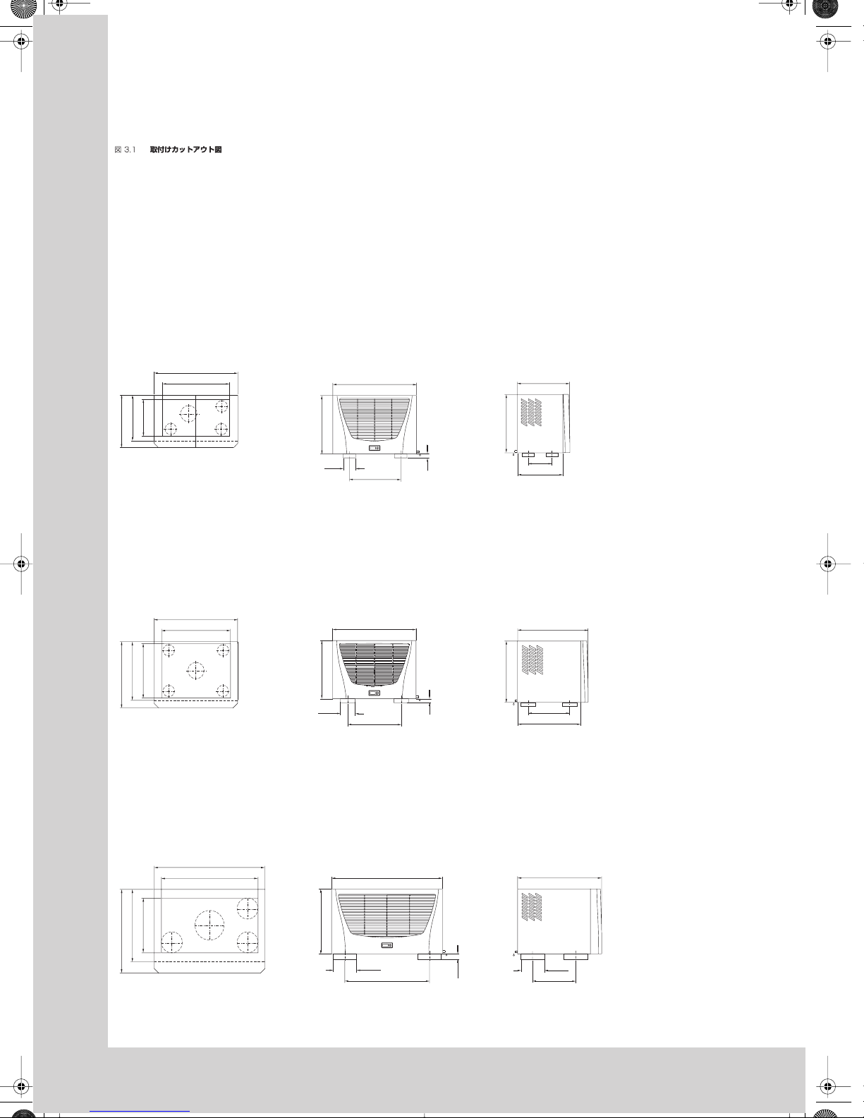
Abb. 3.1
Montageausschnitte
Fig. 3.1
Mounting cutouts
Fig. 3.1
Découpes de montage
Afb. 3.1
Montage-uitsparingen
Bild 3.1
Håltagning
Fig. 3.1
Dime di foratura
Fig. 3.1
Recorte del montaje
Montageausschnitt
SK 3359.... / SK 3382....
Montageausschnitt
SK 3383.... / SK 3384.... / SK 3385....
Montageausschnitt
SK 3386.... / SK 3387....
475
260
326
375
597
475
415
420
280
597
415
380
Ø 100
27
490
597
420
390
475
580
520
392
796
692
470
796
538
Ø 150
38.5
580
238
Ø 150
01_SK3382_2_3.fm Seite 2 Freitag, 5. März 2004 4:27 16
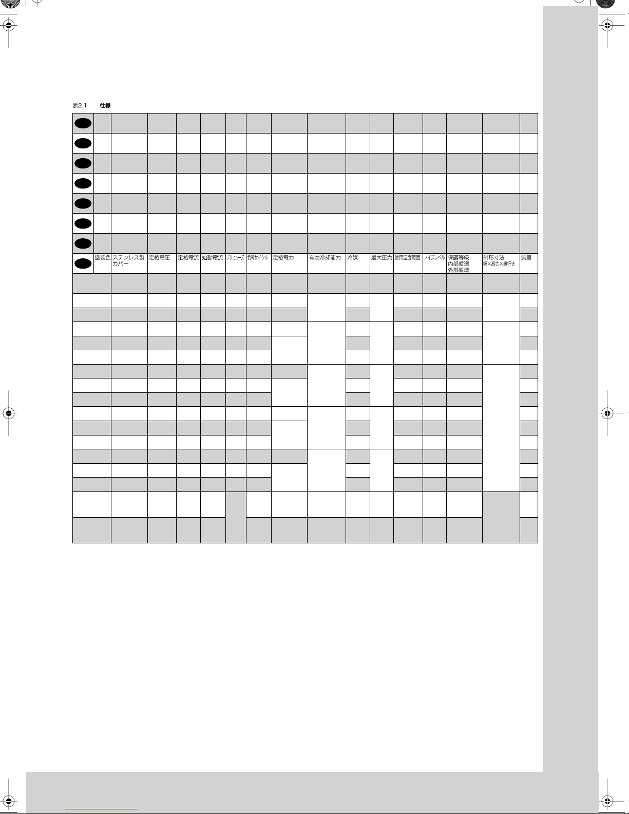
Tab. 2.1
Tec hnische Daten
Tab. 2.1
Tec hnical data
Tab. 2.1
Données techniques
Tab. 2.1
Tec hnische gegevens
Tab. 2.1
Tekniska data
Tab. 2.1
Caratteristiche tecniche
Tab. 2.1
Datos técnicos
Farbton
RAL
7035
Edelstahlhaube
1.4301
Bemessungsspannung
Bemessungsstrom
Anlaufstrom
Vorsicherung T
Einschaltdauer
Bemessungsleistung
Nutzkühlleistung Kältemittel zul.
Druck
PS
Temperaturbereich
Geräuschpegel
Schutzart
Innenkreislauf
Außenkreislauf
Abmessungen
(B x H x T)
mm
Gewicht
Colour
RAL
7035
Stainless
steel cover
1.4301
Operating
voltage
Rated
current
Starting
current
Pre-fuse TDuty cycle Nom.
refrigeration
Useful cooling
output
Refrigerant Permis-
sible
pressure
Temperature
range
Noise
level
Protection categ.
Internal circuit
External circuit
Dimensions
(W x H x D)
mm
Weight
Coloris
RAL
7035
Capot en acier
inoxydable
1.4301
Tension
nominale
Courant
nominal
Courant de
démarrage
Dispositif
de
sécurité T
Durée de
mise en
circuit
Puissance
nominale
Puissance
frigorifique
de régime
Fluide
frigorigène
Pression
de régime
autor.
Plage de
température
Niveau
sonore
Degré de protect.
Circuit intérieur
Circuit extérieur
Dimensions
(L x H x P)
mm
Poids
Kleur
RAL
7035
RVS mantel
1.4301
Bedrijfsspanning
Nominale
stroom
Aanloopstroom
Primaire
zekering
T
Inschakelduur
Nominaal
vermogen
Nuttig
koelvermogen
Koelmiddel
p. max. Temperatuur-
bereik
Geluidsnivo
Beschermklasse
Inwendig circuit
Uitwend. circuit
Afmetingen
(B x H x D)
mm
Gewicht
Färgton
RAL
7035
Huv i rostfritt
stål 1.4301
Anslutningsspänning
Märkström
Startström För-
säkring
gL
Inkopplingstid
Märkeffekt Effektiv
kyleffekt
Kylmedel Tillåtet
driftsövertryck
Temperaturområde
Ljudnivå Kapslingsklass
Inre kretslopp
Yttre kretslopp
Mått
(B x H x D)
mm
Vikt
Colore
RAL
7035
Cover in acciaio
inox 1.4301
Tensione
nominale
Corrente
nominale
Corrente
di spunto
Fusibili T Ciclo d’in-
serzione
Potenza
nominale
Potenza
frigorifera utile
Fluido
frigorigeno
Pressione
max.
Campo di
temperatura
Livello
di rumore
Grado di protez.
Circuito interno
Circuito esterno
Dimensioni
(L x A x P)
mm
Peso
Color
RAL
7035
Cubierta de acero
inoxidable
1.4301
Tensión
de
servicio
Intensidad
nominal
Intensidad
de
arranque
Fusible T Duración
de
conexión
Potencia
nominal
Potencia
frigorífica útil
Fluido
frigorífico
Presión
máxima
admis.
Campo de
temperaturas
Nivel
de ruido
Protección
Circuito interior
Circuito exterior
Dimensiones
(anch. x alt.
x prof.) mm
Peso
RAL
7035
1.4301
L35 L 35
L35 L 50
DIN 3168/EN 814
L35 L 35
L35 L 50
EN 60529
SK 3382.100
SK 3382.500
SK 3382.200
SK 3382.600
230 V,
50/ 60 Hz
2.7 A/
2.9 A
9.2 A/
10.2 A
10.0 A/
10.0 A
100 %
360 W/410 W
410 W/450 W
500 W/510 W
270 W/370 W
R134a,
250 g
25 bar
+20 –
+55°C
<64dB(A)
IP 54
IP 34
597 x 415 x 375
30 kg
SK 3382.110
SK 3382.510
SK 3382.210
SK 3382.610
115 V,
50/ 60 Hz
5.5 A/
6.0 A
18.4 A/
18.4 A
10.0 A/
10.0 A
100 %
370 W/420 W
420 W/470 W
R134a,
250 g
+20 –
+55°C
<64dB(A)
IP 54
IP 34
35 kg
SK 3359.100
SK 3359.500
SK 3359.200
SK 3359.600
230 V,
50/ 60 Hz
3.0 A/
3.9 A
10.0 A/
10.7 A
10.0 A/
10.0 A
100 %
410 W/520 W
490 W/600 W
750 W/810 W
545 W/590 W
R134a,
300 g
25 bar
+20 –
+55°C
<64dB(A)
IP 54
IP 34
596 x 415 x 375
32 kg
SK 3359.110
SK 3359.510
SK 3359.210
SK 3359.610
115 V,
50/ 60 Hz
6.0 A/
7.8 A
20.0 A/
21.4 A
16.0 A/
16.0 A
100 %
420 W/535 W
500 W/615 W
R134a,
300 g
+20 –
+55°C
<64dB(A)
IP 54
IP 44
34 kg
SK 3359.140
SK 3359.540
SK 3359.240
SK 3359.640
400 V, 2 ~,
50/60 Hz
1.7 A/
2.2 A
5.8 A/
6.2 A
10.0 A/
10.0 A
100 %
R134a,
300 g
+20 –
+55°C
<64dB(A)
IP 54
IP 34
34 kg
SK 3383.100
SK 3383.500
SK 3383.200
SK 3383.600
230 V,
50/ 60 Hz
4.3 A/
4.5 A
15.5 A/
15.5 A
10.0 A/
10.0 A
100 %
550 W/650 W
660 W/750 W
1000 W/1080 W
760 W/ 820 W
R134a,
500 g
25 bar
+20 –
+55°C
<64dB(A)
IP 54
IP 34
597 x 415 x 475
40 kg
SK 3383.110
SK 3383.510
SK 3383.210
SK 3383.610
115 V,
50/ 60 Hz
8.3 A/
8.7 A
25.3 A/
24.3 A
16.0 A/
16.0 A
100 %
580 W/660 W
670 W/755 W
R134a,
500 g
+20 –
+55°C
<64dB(A)
IP 54
IP 44
46 kg
SK 3383.140
SK 3383.540
SK 3383.240
SK 3383.640
400 V, 2 ~,
50/60 Hz
2.4 A/
2.4 A
8.0 A/
8.8 A
10.0 A/
10.0 A
100%
R134a,
500 g
+20 –
+55°C
<64dB(A)
IP 54
IP 34
46 kg
SK 3384.100
SK 3384.500
SK 3384.200
SK 3384.600
230 V,
50/ 60 Hz
5.7 A/
6.8 A
16.6 A/
17.1 A
10.0 A/
10.0 A
100%
815 W/ 930 W
950 W/1090 W
1500 W/1520 W
1100 W/1210 W
R134a,
500 g
25 bar
+20 –
+55°C
<64dB(A)
IP 54
IP 34
41 kg
SK 3384.110
SK 3384.510
SK 3384.210
SK 3384.610
115 V,
50/ 60 Hz
12.5 A/
14.1 A
30.7 A/
29.1 A
20.0 A/
20.0 A
100%
850 W/ 950 W
1000 W/1150 W
R134a,
500 g
+20 –
+55°C
<64dB(A)
IP 54
IP 34
47 kg
SK 3384.140
SK 3384.540
SK 3384.240
SK 3384.640
400 V, 2 ~,
50/60 Hz
3.4 A/
4.0 A
9.8 A/
9.6 A
10.0 A/
10.0 A
100%
R134a,
500 g
+20 –
+55°C
<64dB(A)
IP 54
IP 34
47 kg
SK 3385.100
SK 3385.500
SK 3385.200
SK 3385.600
230 V,
50/ 60 Hz
5.7 A/
6.6 A
16.8 A/
18.4 A
10.0 A/
10.0 A
100 %
1000 W/1175 W
1100 W/1310 W
2000 W/2130 W
1570 W/1670 W
R134a,
950 g
25 bar
+20 –
+55°C
<64dB(A)
IP 54
IP 34
42 kg
SK 3385.110
SK 3385.510
SK 3385.210
SK 3385.610
115 V,
50/ 60 Hz
13.0 A/
14.2 A
36.0 A/
32.0 A
20.0 A/
20.0 A
100 %
1050 W/1250 W
1160 W/1380 W
R134a,
950 g
+20 –
+55°C
<64dB(A)
IP 54
IP 34
48 kg
SK 3385.140
SK 3385.540
SK 3385.240
SK 3385.640
400 V, 2 ~,
50/60 Hz
3.3 A/
3.8 A
10.0 A/
12.0 A
10.0 A/
10.0 A
100%
R134a,
950 g
+20 –
+55°C
<64dB(A)
IP 54
IP 34
48 kg
SK 3386.140
SK 3386.540
SK 3386.240
SK 3386.640
400 V, 3 ~,
50 Hz,
460 V, 3 ~,
60 Hz
3.0 A/
3.1 A
8.0 A/
9.0 A
10.0 A*/
10.0 A*
100%
1180 W/1490 W
1430 W/1770 W
3000 W/3300 W
2460 W/2750 W
R134a,
1600 g
25 bar
+20 –
+55°C
<67dB(A)
IP 54
IP 34
796 x 470 x 580
70 kg
SK 3387.140
SK 3387.540
SK 3387.240
SK 3387.640
400 V, 3 ~,
50 Hz
460 V, 3 ~,
60 Hz
3.5 A/
3.6 A
17.0 A/
19.0 A
100%
1620 W/2060 W
1870 W/2340 W
4000 W/4200 W
3250 W/3490 W
R134a,
1800 g
25 bar
+20 –
+55°C
<67dB(A)
IP 54
IP 34
77 kg
Technische Änderungen vorbehalten.
Technical modifications reserved.
Sous réserve de modifications techniques.
Technische wijzigingen voorbehouden.
Tekniska ändringar förbehålles.
Rittal si riserva di apportare eventuali modifiche tecniche.
Se reserva el derecho a realizar cambios técnicos.
* Motorschutzschalter, motor circuit breaker, disjoncteur-protecteur, motorbeveiligingsschakelaar, motorskyddsbrytare, salvamotore, guardamotor.
D
GB
F
NL
S
I
E
J
3
01_SK3382_2_3.fm Seite 3 Freitag, 5. März 2004 4:27 16
8
Contents
1. Application
2. Technical data
3. Assembly of roof-mounted units
4. Safety notices
5. Electrical connection
6. Commencing operation and control
behaviour
7. Supplementary functions
8. BUS system
9. Technical information
10. Handling Instructions
11. Scope of supply and guarantee
12. Display screen and system analysis
13. Comfort control programming
1. Application
Enclosure cooling units are designed and built
to dissipate heat from enclosures by cooling the
air inside the enclosure and protecting temperature-sensitive components. Enclosure cooling
units are particularly suitable for a temperature
range of +40°C to +55°C.
2. Technical data
(see table 2.1)
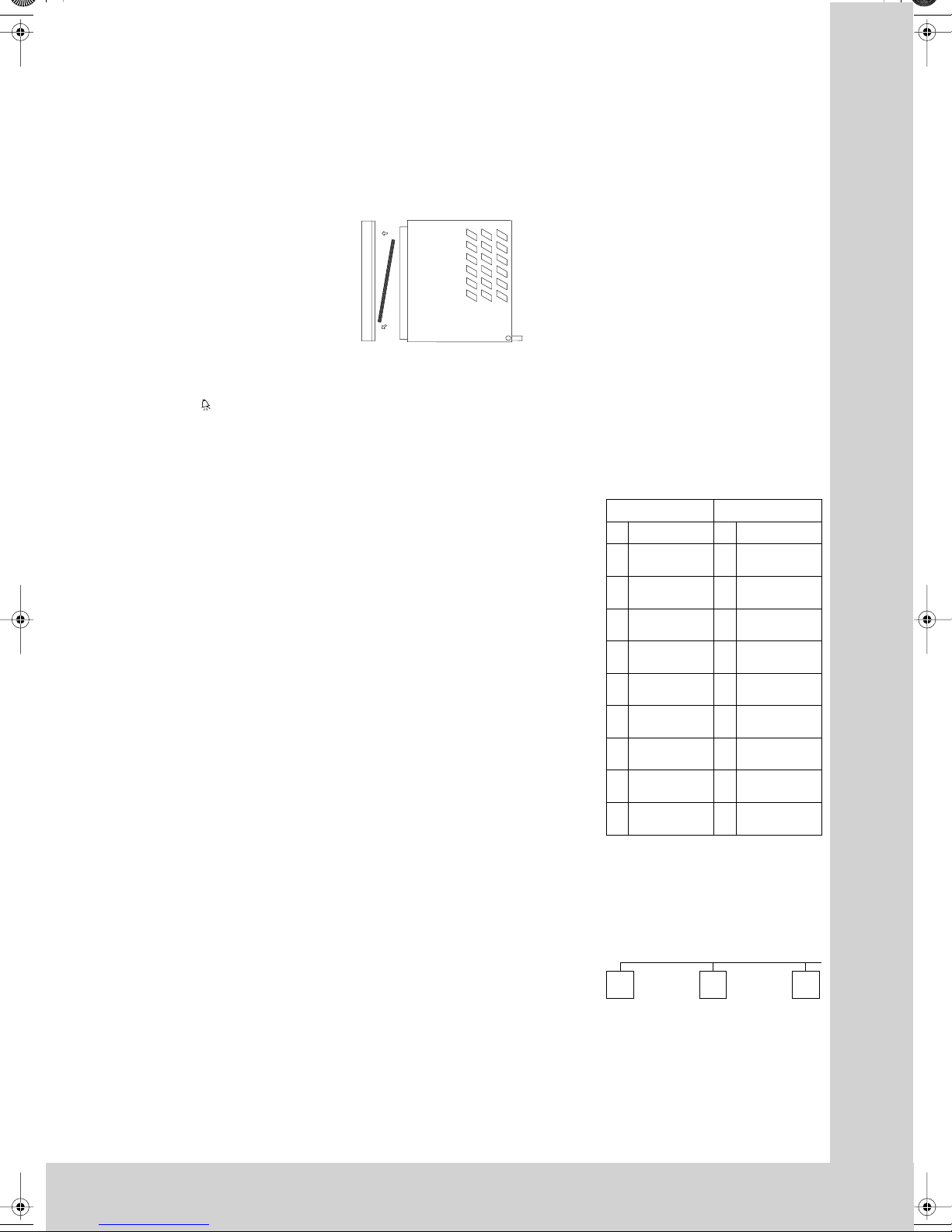
3. Assembly of
roof-mounted units
The roof-mounted unit can be assembled as
standard. Make the cutout at the mounting place
as shown in Fig. 3.1. Attach the enclosed sealing
plate under the plastic base of the cooling unit
and the enclosed sealing frame to the cut out roof
plate. After the assembly of the unit, screw
double-threaded bolts in the holes of the plastic
base at the bottom side of the unit. After this,
insert the sliding part, slide it over the cutout
and fasten it by means of washers and nuts.
4. Safety notices
The following safety notices are to be observed
in their entirety for the correct use of the
equipment:
Prior to mounting, ensure that:
the site for the enclosure, and hence the
arrangement of the cooling unit, is selected
so as to ensure good ventilation;
the location is free from excessive dirt and
moisture;
the cutout for air extraction is located in the
upper area of the enclosure;
the mains connection ratings, as stated on
the rating plate, are available;
the ambient temperature does not exceed
+55°C;
the packaging shows no signs of damage.
Traces of oil on damaged packaging are an
indication of refrigerant loss and of leakage in
the unit system. Any damage to the packaging
may be the cause of subsequent malfunctions;
the enclosure is sealed on all sides (IP 54).
Condensation will occur if the enclosure is
leaky;
the distance of the units from the wall should
not be less than 200 mm;
air inlet and outlet are not obstructed on the
inside of the enclosure;
units are only fitted horizontally in the specified position.
Max. deviation from the true horizontal: 2°;
condensate drainage is provided
(see 9.3);
electrical connection and repair are carried
out only by authorised personnel. Use only
original replacement parts!
to avoid an increase in condensation, a dooroperated switch (e.g. PS 4127.000) should be
used which will switch the cooling unit off
when the enclosure door is opened (see 7.3);
losses from the components installed in
the enclosure must not exceed the specific
refrigeration capacity of the cooling unit itself;
the customer must not modify the cooling unit
in any way.
Important note:
In order to achieve a permanent seal between
cooling unit and enclosure, the mounting surface
should be reinforced or supported where necessary (see example fig. 3.2), especially in case of
larger roof surfaces. Observe assembly instruction under heading 3.
Fig. 3.2
Roof plate reinforcement
with TS 8 enclosure
Accessory for roof plate reinforcement with TS:
Mounting rail
Sliding nut
Mounting bracket
Threaded block
(see Accessories in the Rittal Catalogue)
Transportation by means of a crane:
Remove blanking plug in the cover and
screw in eyebolt M12.
5. Electrical connection
The connected voltage and frequency must
correspond to the values stated on the rating
plate. During commissioning, the data on the
rating plate of the device shall apply. The cooling
unit must be connected to the mains via an all-pin
isolating device, which ensures at least 3 mm
contact opening when switched off. The unit must
not have any additional temperature control
connected up-stream at the supply end. The fans
and compressors built into single and threephase devices are intrinsically safe (thermal
winding protection).
This also applies to SK 3382...., SK 3359....,
SK 3383...., SK 3384...., SK 3385....
transformer types, and to specially rated units
which are also fitted with a transformer.
Line protection should be provided by means of
the pre-fuse specified on the rating plate. Only
one automatic cutout should be connected between the cooling unit and the power supply. A
time-lag backup-fuse as specified on the rating
plate (safety cutout K-characteristic or time-lag
lead fuse) is mandatory.
The three phase supplies for the SK 3386.... /
SK 3387.... must be connected via a motor
safety switch to a TN grid with grounded star
point. Summation current as specified on the
rating plate. Specially rated three-phase units
must be protected by means of transformer safety
switches (category AC-6A) specified on the rating
plate.
For units designed for three phase 400/460 V,
the rotary field or the absence of a phase is also
monitored. If the rotary field is incorrect or a phase
is absent, the unit will not run. Observe the
relevant regulations during installation!
6.Commencing operation
and control behaviour
Following the completion of mounting and a
waiting period of approximately 30 minutes
(to allow oil to collect in the compressor in order
to ensure lubrication and cooling).
6.1 Basic control system
Version .....100 / .110 / .140
The cooling unit operates automatically, i.e. after
electrical connection, the evaporator fan will run
continuously to circulate the air inside the enclosure. The installed basic controller (setting the
desired internal temperature; factory setting
+35°C) provides automatic control switch-off of
the cooling unit by the set value of the fixed
switching difference of 5 K.
English
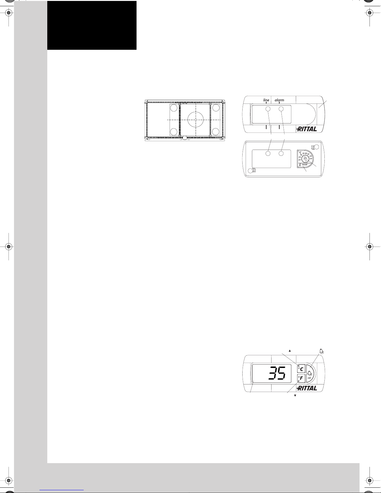
6.1.1 Temperature setting at the basic
controller
First of all, the louvred grille with the incorporated
display is to be removed from the unit. The display
lock is then to be slackened and this is to be
pushed forward off the louvred grille. Finally, the
display screen (1) is carefully removed, e.g. with a
screwdriver. The desired nominal temperature can
be set on the potentiometer (2) which is now
accessible. After the temperature has been set,
the display of all screens in the louvred grille is to
be locked once more. The louvred grille is to be
fastened to the unit again.
Fig. 6.1
Basic controller
6.1.2 Operation of the basic controller
The basic controller monitors and controls the
cooling unit. After the supply voltage has been
connected, the green LED (3) lights to indicate
readiness for operation. The green LED is
connected in series with a door limit switch, and
flashes if the enclosure door is opened. The red
LED (4) signals too high a temperature inside the
enclosure; at 5 K above the set value, the red LED
comes on permanently. In addition, the excess
temperature message can still be queried via an
integrated potential-free contact in the cooling
unit connection terminal.
K1 fault signal relay with changeover contact
Te rminal 3: NC (normally closed)
Te rminal 4: C (connection between voltage
supply and fault signal relay)
Te rminal 5: NO (normally open)
The definitions NC and NO refer to the deenergised state. As soon as voltage is applied to
the cooling unit, the fault signal relay picks up.
As a result, the relay contacts change their state
(contact 3 – 4 open; contact 4 – 5 closed),
representing the normal operating status of the
cooling unit. As soon as a system message
occurs or the voltage supply is interrupted, the
relay drops out. (see circuit diagrams on
page 37).
The high pressure alarm in the cooling circuit is
indicated by the red LED flashing. In this case,
the unit is to be reset manually, by pressing the
rubberized potentiometer display (5) for
3 seconds (see 6.1.1).
6.2 Comfort controller control
Version .....500 / .510 / .540
Fig. 6.2
Comfort controller
34
1
2
5
H2 = Button
H4 = Button
/set
°C
H3 = Button
°F
H1 = Display terminal
After electrical connection the internal fan turns on
and circulates the enclosure air. This helps assure
even temperature distribution within the enclosure.
The condenser fan and compressor are controlled
by the Comfort controller. The minimum break time
is 3 min. The switching difference is 5 K, but
can be set in the range 2 – 10 K. To avoid short
switching cycles and hence the danger of
inadequate or only partial cooling in some
sections of the enclosure, the switching difference
should be set to be only as low as necessary.
For economic reasons (energy saving), the
nominal value of the internal enclosure
temperature T
as low as necessary.
6.2.1 Operation of the Comfort controller
The display terminal H1 consists of a 3 position
7-segment display which indicates the enclosure
internal temperature in °C or °F (changeable) as
well as any fault codes. The actual enclosure
internal temperature is constantly displayed on
H1. When a system message is generated, this
alternates in the display with the current internal
enclosure temperature. While programming the
unit, the programming level and prescribed value
are also displayed.
Test mode
By simultaneously holding down keys H2
°C key) and H4 ( /set key) for 5 seconds, the
(
cooling unit will commence cooling operation,
irrespective of the setpoint. The door limit switch
function is disregarded in such cases. After
approximately 5 minutes or upon reaching 15°C,
the device deactivates cooling operation once
again.
6.2.2
In the EEPROM of the Comfort controller various
parameters are stored which can be changed by
using the buttons H2, H3 and H4. 24 changeable
parameters can be set via 24 programme levels in
the stated ranges (max. and min. values).
To this end, input code “22” is required
(see diagram 13.1).
The H2, H3 and H4 keys are multiple occupancy.
To access programming mode, set 5 sec is to be
pressed and held down.
Primary occupancy (only diode displays):
H2: °C, H3: °F, H4: Alarm
Secondary occupancy (for programming):
H2: Arrow upwards, H3: Arrow downwards,
H4: set
Programming via diagnostic software (order no.
SK 3159.100) is also an option. The programming
cable interface is the connecting cable plug,
located on the rear of the Comfort controller. To do
this, the louvred grille also is to be removed if
necessary.
6.2.3 System messaging equipment
All system messages at the cooling unit are
recorded and displayed as an error number
by H1. System messages alternate in the display
with the current internal enclosure temperature.
(see 12. Comfort control fault display and error
analysis).
6.2.3.1 System message contacts
Both relays are normally closed.
All system messages assigned to an individual
relay result in it opening. If the control voltage
fails, this also results in the relay opening and can
hence be captured and documented in the log
file. According to individual weighting, all system
messages can be assigned to both relays or
suppressed. Terminal strip X3 provides the
connection. See the wiring diagram for contact
data and occupancy.
K1/K2 fault signal relay (normally open contact):
Te rminal 3: Fault signal relay 1
Te rminal 4: Voltage supply connection for both
Te rminal 5: Fault signal relay 2
(see the circuit diagrams on page 37).
should also be set to be only
i
(see diagram 13.1 Programming)
Programming
(see 13.1 Comfort controller
programming)
(K1 and K2; potential free)
fault signal relays
7. Supplementary functions
7.1 Filter mat use and changing
The PU foam filter mat available as an accessory
is coarse and filters large dust particles or fluff
from the air. Metallic filter mats are used to trap
oil condensate. These are also available as an
accessory. Subject to the suction of the blower
being high enough, fine dust is blown through
the filter mat and the external circuit of the unit.
This does not affect the unit's operation.
Fig.7.1
Filter mat replacement
2.
1.
7.2 Filter mat monitoring
Function of the filter mat monitor:
The filter mat is monitored for soiling by measuring the temperature difference in the external circulation of the cooling unit (see diagram 13.1:
Programming on page 45). In the event of any
filter mat soiling, the temperature difference will
increase. The nominal value of the temperature
difference in the external circuit is matched to the
relevant operating points in the characteristic
fields. Hence there is no requirement to adjust the
nominal value for different unit operating points.
7.3 Door limit switch S1
(supplied by customer)
Where a door limit switch is used and the enclosure door is open (contact is closed when door is
open), the cooling unit (fans and condenser) will
switch off after approx. 15 s. This only applies to
devices with a Comfort controller and devices
with a three-phase connection to the basic controller. For devices with a basic controller (115 V,
230 V and 400 V, 2~), the internal fan is not
switched off when using a door limit switch.
Thereby avoiding an increase in condensation
while the door is open. To avoid cyclic operation,
switch-on of condenser and external fan is
delayed by about 3 minutes after the cooling unit
has been switched off.
The internal fan will start up after about 15 s on
closure of the door. Connection is made at the
terminals 1 and 2. The extra low voltage is
supplied by the internal power pack, current is
approx. 30 mA DC. Each door limit switch must
only be assigned to one cooling unit. Several door
limit switches may be operated on one cooling
unit (parallel connection). The minimum crosssection of the connection cable is 0.3 mm
cable length of 2 m. The resistance of the door
limit switch contact must not exceed a maximum
of 50Ω.
Only connect the door limit switch to the
cooling unit’s own DC supply!
7.4 Interface X3 (option)
(Connector X3)
Note!
The electrical signals at the interface are of an
extra-low voltage (not extra-low safety voltages
to EN 60 335).
The 9-pin SUB-D socket X3 can be used to
connect additional interface cards for integrating
cooling units with higher level monitoring systems.
These cards are also available as an accessory.
(Interface card: Model No. SK 3124.200).
2
for a
8. BUS system
(Model No.: Master-slave cable SK 3124.100)
8.1 General
The BUS system allows a maximum of 10 cooling units to be interconnected.
As a result, the following functions are available
to the operator:
Parallel unit control (the cooling units in the
network can be simultaneously switched
on and off)
Parallel door status messages (“door open”)
Parallel collective fault message
The data exchange is carried out using masterslave cables (shielded, two-wire leads). All units
are assigned an address. This address also
includes the ID for “master” or “slave”.
8.2 Installation notices for the X2 interface
(Jack X2)
Note!
The electrical signals at the interface are of an
extra-low voltage (not extra-low safety voltages
to EN 60 335). Always heed the following notes!
De-energise the cooling units to be
connected.
Ensure proper electrical insulation.
Make sure the cables are not laid in parallel
to power lines.
Make sure that the lines are short.
8.3 Programming the cooling unit
See diagram 13.1 for details on programming.
ID’s:
Master cooling unit Slave cooling unit
00 Basic state 00 Basic state
Master
01
with 1 slave
Master
02
with 2 slaves
Master
03
with 3 slaves
Master
04
with 4 slaves
Master
05
with 5 slaves
Master
06
with 6 slaves
Master
07
with 7 slaves
Master
08
with 8 slaves
Master
09
with 9 slaves
Note
Only one unit may be configured as master; the
address ID must match the number of slave
units.
The individual slave units must have different
addresses; the addresses must be in ascending
order (without gaps in between).
Example:
1 master cooling unit with 2 slave cooling units
Master
02
(see wiring example of master/slave and door
limit function, page 42/43).
Slave
11
11
12
13
14
15
16
17
18
19
Slave
with address 1
Slave
with address 2
Slave
with address 3
Slave
with address 4
Slave
with address 5
Slave
with address 6
Slave
with address 7
Slave
with address 8
Slave
with address 9
Slave
12
9
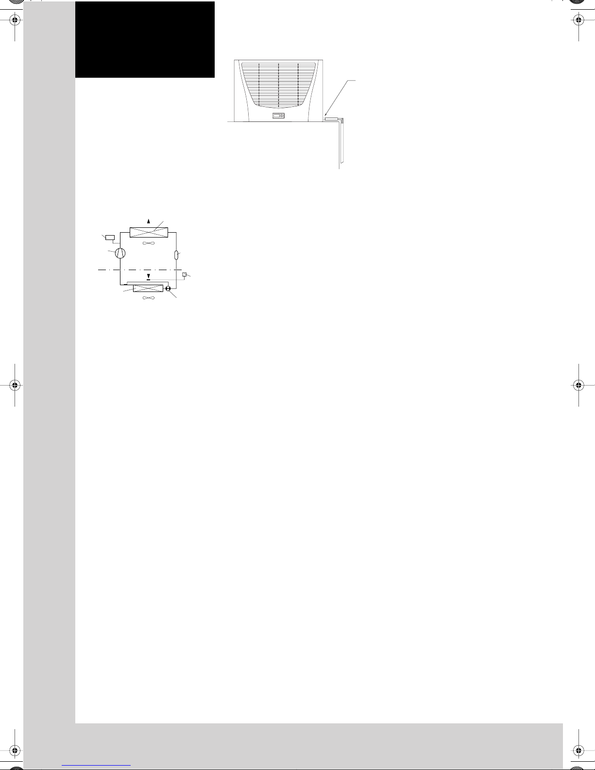
Fig. 9.3
Condensate discharge
English
9.Technical information
The cooling unit (compressor refrigeration unit)
consists of four main components: the coolant
compressor, evaporator, condenser, and the
control or expansion valve, which are connected
by suitable pipework. This circuit is filled with
a readily boiling substance, the refrigerant. The
R134a (CH
rine. It has an ozone destroying potential (ODP)
of 0 and is therefore environmentally friendly. A
filter dryer which is integrated in the hermetically
sealed cooling circuit, provides effective protection against moisture, acid, dirt particles, and
foreign bodies within the cooling circuit.
9.1 Operation of the cooling unit
Fig. 9.1
Compressor
External circuit
Internal circuit
The compressor takes the gaseous refrigerant
from the evaporator and compresses it to a
higher pressure in the condenser. During this
process the temperature of the refrigerant rises
above the ambient temperature and heat can be
dissipated to the environment via the surface of
the condenser. Then the refrigerant is liquefied
and, by means of a thermostatically controlled
expansion valve, returned to the evaporator,
where it evaporates at low pressure. The heat
required for complete evaporation is drawn from
the enclosure interior causing it to cool down.
The cooling cycle is thus completed, the aforementioned process of the heat transfer starts
afresh.
9.2 Safety equipment
The cooling circuit of the cooling unit has a
component-tested, high-pressure monitor to
EN 12 263, which is set to maximum PS (allowed
pressure) and operates via an automatic reset
device in case of recurring pressure drop. Temperature monitoring will prevent the evaporator
from icing up. If there is a risk of icing up, the
compressor is switched off and automatically
switched on again at higher temperatures.
The refrigerant compressor and the fans are
equipped with thermal winding protection
switches against excess current and excess
temperatures.
9.3 Condensate discharge
A cast gutter in the evaporator tray ensures that
any condesate which may form on the evaporator (at high air humidity, low temperatures inside
the enclosure), is drained away to the right or
rear of the unit. For this purpose, a length of
hose should be fitted to one of the two condensate pipe connection pieces (see fig. 9.3). The
other drain that is not used has to be sealed
accordingly. The condensate must be able to
run off freely. If the condensate is to be drained
off over a greater distance, then care must be
taken that the hose is free from kinks and a
check for correct drainage made. Units with a
comfort controller have an additional condensate alarm.
FCF3) refrigerant is free from chlo-
2
Operation of the cooling unit
H
PSA
monitor
Fan 2
Evaporator
Fan 1
Liquefier
Filter
dryer
Thermostat
Expansion valve
1
′′
/
2
10. Handling Instructions
Storage, maintenance, transport and disposal
As a maintenance-free, hermetically sealed
system, the cooling circuit has been filled in the
factory with the required amount of refrigerant,
and tested for leaks and subjected to a function
trial run.
The installed maintenance-free fans use ball
bearings, they are protected against moisture and
dust, and are fitted with a temperature monitor.
The life expectancy is at least 30,000 operating
hours. The cooling unit is thus largely maintenance free. All that may be required from time to
time is that the components of the external air
circuit are cleaned by compressed air. The use of
a filter mat is recommended only if large particles
of lint are present in the air, so that blockage of the
condenser is prevented. (Filter mat replacement,
fig. 7.1). Note: Prior to any maintenance work, the
power to the cooling unit must be disconnected.
Storage temperature: The cooling units must not
be exposed to temperatures above +70°C.
Transport position: The cooling units must always
be transported upright.
Waste disposal: The closed cooling circuit
contains refrigerant and oil which must be
correctly disposed of for the protection of the
environment. Disposal can be carried out at
Rittal.
We reserve the right to make technical
modifications.
11. Scope of supply and
guarantee
1 cooling unit, ready for connection
1 drilling template
1 sealing plate
1 sealing frame
1 set of mounting and operating instructions
1 plug-in terminal strip
Guarantee:
This unit is covered by a 1-year guarantee from the
date of supply, subject to correct usage (see also
Safety notices under heading 4.). Within this period,
the returned unit will be repaired in the factory or
replaced free of charge. The cooling unit is to be
used for the cooling of enclosures only. If it is connected or handled improperly the manufacturer’s
guarantee does not apply and in this case we are
not liable for any damage caused.
10
 Loading...