

Rittal SK 3378.200, SK 3378.280 Assembly And Operating Instructions Manual

Air/water heat exchangers
SK 3378.200
SK 3378.280
Assembly and operating instructions
Download options
Download options
Hinweis:
Die Montage-, Installations- und Bedienungsanleitung ist auch als Download unter
www.rittal.de verfügbar.
Note:
The assembly and operating instructions are
available for downloading from
www.rittal.com.
Remarque :
La notice de montage, d'installation et d'emploi peut être téléchargée depuis le site
www.rittal.fr.
Opmerking:
De montage-, installatie- en gebruikshandlei-
ding is ook te downloaden via www.rittal.nl.
Obs:
Montage-, installations- och bruksanvisningen kan även laddas ner på www.rittal.se.
Nota:
Las instrucciones de montaje, instalación y
puesta en marcha también están disponibles
para su descarga en www.rittal.es.
Nota:
Le istruzioni di montaggio, installazione e uso
possono anche essere scaricate dal sito
www.rittal.it.
注記:
この取扱説明書 ( 組立・設置および運用マ
ニュアル ) は、www.rittal.co.jp からもダウ
ンロードできます。
2 Rittal air/water heat exchanger
Safety instructions and warnings
Safety instructions and warnings
Warn- und Sicherheitshinweise
Warnung!
Bitte beachten Sie die maximal zulässigen Hebegewichte für Personen. Ggf.
ist eine Hebevorrichtung zu verwenden.
Arbeiten an elektrischen Anlagen oder
Betriebsmitteln dürfen nur von einer
Elektrofachkraft oder von unterwiesenem Personal unter Leitung und Aufsicht einer Elektrofachkraft den
elektrotechnischen Regeln entsprechend vorgenommen werden.
Der Luft/Wasser-Wärmetauscher darf
erst nach Lesen dieser Informationen
von den o. g. Personen angeschlossen
werden!
Es darf nur spannungsisoliertes Werkzeug benutzt werden.
Die Anschlussvorschriften des zuständigen Stromversorgungsunternehmens
sind zu beachten.
Der Luft/Wasser-Wärmetauscher muss
über eine allpolige Trennvorrichtung
nach Überspannungskategorie III (IEC
61 058-1) an das Netz angeschlossen
werden.
Consignes de sécurité
Avertissement !
Veuillez tenir compte du poids de levage
maximal autorisé pour les personnes et
le cas échéant utilisez un appareil de levage.
Seuls les électriciens spécialisés ou les
personnes dûment instruites opérant
sous la direction et la surveillance d'un
électricien spécialisé, sont autorisés à
pratiquer des interventions sur les installations ou appareils électriques, conformément aux règles de l'électrotechnique.
Les personnes mentionnées ci-dessus
ne sont autorisées à raccorder l'échangeur thermique air/eau qu'après avoir lu
ces informations !
Utiliser exclusivement des outils isolés.
Respecter les directives de raccorde-
ment du fournisseur d'électricité compétent.
L'échangeur thermique air/eau doit être
raccordé au réseau par l'intermédiaire
d'un dispositif de coupure monophasé
de catégorie III de surtension (CEI
61 058-1).
DE
Der Luft/Wasser-Wärmetauscher ist
erst nach Trennung von allen Spannungsquellen spannungsfrei!
Schalten Sie den Luft/Wasser-Wärmetauscher vor dem Öffnen der ElektroAnschlussbox und vor Arbeiten am
Wasserkreislauf spannungsfrei und sichern Sie ihn gegen versehentliches
Wiedereinschalten.
Die Spannungszuschaltung darf erst erfolgen, wenn das Abdeckblech der
Elektro-Anschlussbox ordnungsgemäß
verschraubt ist.
Vorsicht!
Verwenden Sie niemals brennbare Flüssigkeiten zur Reinigung des Luft/Wasser-Wärmetauschers.
An nicht vollständig entgrateten Bohrungen und Ausschnitten besteht
Schnittgefahr, insbesondere bei der
Montage des Luft/Wasser-Wärmetauschers.
FR
L'échangeur thermique air/eau est hors
tension uniquement après avoir débranché toutes les sources de tension !
Mettre l'échangeur thermique air/eau
hors tension avant d'ouvrir le boîtier de
raccordement électrique ou de travailler
sur le circuit d'eau et prévenir toute remise en circuit inopinée.
La mise sous tension doit avoir lieu uniquement lorsque la face avant en tôle
du boîtier de raccordement électrique
est correctement vissée.
Prudence !
Ne jamais utiliser de liquides inflammables pour le nettoyage de l'échangeur thermique air/eau.
Il y a risque de coupures au niveau des
perçages et découpes qui ne sont pas
complètement ébavurés, en particulier
lors du montage de l'échangeur thermique air/eau.
Safety instructions and warnings
Warning!
Please note the maximum weights that
may be lifted by individuals. It may be
necessary to use lifting gear.
Work on electrical systems or equipment may only be carried out by an
electrician or by trained personnel under
the guidance and supervision of an
electrician. All work must be carried out
in accordance with electrical engineering regulations.
The air/water heat exchanger may only
be connected after the above-mentioned personnel have read this information!
Use only insulated tools.
Follow the connection regulations of the
appropriate electrical supply company.
The air/water heat exchanger must be
connected to the mains via an all-pin
isolating device to overvoltage categoryIII (IEC 61 058-1).
EN
The air/water heat exchanger is not deenergised until all of the voltage sources
have been disconnected!
Switch off the power supply to the air/
water heat exchanger before opening
the electrical connection box and before
working on the water circuit, and take
suitable precautions against it being accidentally switched on again.
The power supply must not be switched
back on until the cover plate of the electrical connection box has been properly
screw-fastened into position.
Caution!
Never use flammable liquids for cleaning
the air/water heat exchanger.
There is a risk of cutting injury around all
drill holes and cut-outs which have not
been fully deburred, especially during
mounting of the air/water heat exchanger.
Rittal air/water heat exchanger 3

Contents
EN
Contents
Download options.......................................2
Safety instructions and warnings.................3
1 Notes on documentation .................. 5
1.1 CE label ....................................................... 5
1.2 Storing the documents................................. 5
1.3 Symbols used in these operating
instructions .................................................. 5
1.4 Other applicable documents ........................ 5
2 Safety instructions ............................ 5
3 Device description ............................ 6
3.1 Overview...................................................... 6
3.2 Functional description .................................. 6
3.2.1 How it works ......................................................... 6
3.2.2 Control .................................................................. 7
3.2.3 Bus mode ............................................................. 7
3.2.4 Safety equipment .................................................. 7
3.2.5 Condensation ....................................................... 7
3.2.6 Leak detection ...................................................... 7
3.2.7 Door limit switch ................................................... 7
3.2.8 Additional interface X3 .......................................... 7
3.3 Proper use ................................................... 7
3.4 Scope of supply........................................... 7
7 Inspection and maintenance .......... 20
7.1 General ...................................................... 20
7.2 Fan replacement ........................................ 21
8 Draining, storage and disposal ....... 21
9 Technical specifications ................. 22
10 List of spare parts .......................... 23
11 Hydrological data ........................... 24
12 Application example ....................... 25
13 Appendix ....................................... 26
13.1 Characteristic curves.................................. 26
13.1.1 Water resistance ................................................. 26
13.2 Drawings.................................................... 27
13.3 Circuit diagram........................................... 30
14 Declaration of conformity ............... 31
4 Installation ........................................ 8
4.1 Safety instructions........................................ 8
4.2 Siting location requirements ......................... 8
4.3 Assembly procedure .................................... 8
4.3.1 Assembly instructions ........................................... 8
4.3.2 Mounting options .................................................. 9
4.3.3 Connecting the condensate discharge ................ 10
4.4 Connecting the water connection............... 10
4.4.1 Notes on water quality ........................................ 11
4.4.2 Preparation and maintenance of the water in
recooling systems ............................................... 11
4.5 Routing busbars ........................................ 11
4.6 Electrical connection .................................. 12
4.6.1 Notes on electrical installation ............................. 12
4.6.2 Install the power supply ....................................... 13
5 Commissioning ............................... 13
6 Operation ....................................... 14
6.1 Properties .................................................. 14
6.2 Launching test mode ................................. 14
6.3 General programming information .............. 14
6.4 Eco-mode.................................................. 15
6.5 Editable parameters ................................... 16
6.6 Bus connection.......................................... 16
6.7 Programming overview of e-Comfort
controller .................................................... 18
6.8 Defining system messages for evaluation ... 19
6.9 Setting the master-slave identifier............... 19
6.10 Evaluating system messages ..................... 20
4 Rittal air/water heat exchanger
1 Notes on documentation
1 Notes on documentation
1.1 CE label
Rittal GmbH & Co. KG confirms the conformity of the air/
water heat exchanger with the European Union's Machinery Directive 2006/42/EC and EMC Directive 2004/
108/EC. A corresponding declaration of conformity has
been issued and enclosed with the unit.
1.2 Storing the documents
The assembly and operating instructions as well as all
other applicable documents are an integral part of the
product. They must be issued to everyone who works
with the air/water heat exchanger and must always be
available and on hand for operating and maintenance
personnel.
1.3 Symbols used in these operating instructions
The following symbols are used in this documentation:
Warning!
Hazardous situation which may lead to
death or serious injury if the instructions
are not followed.
2 Safety instructions
Please observe the following general safety notes when
assembling and operating the unit:
– Assembly, installation and servicing may only be per-
formed by properly trained specialists.
– Only use the air/water heat exchanger within the pre-
scribed water inlet and operating temperature range.
– Use antifreeze agents only with the manufacturer's
consent.
– Do not obstruct the air inlet and air outlet of the air/wa-
ter heat exchanger inside the enclosure (see section4.3.2 "Mounting options").
– The heat loss of the components installed in the enclo-
sure must not exceed the specific useful cooling output of the air/water heat exchanger.
– The air/water heat exchanger must always be trans-
ported in a vertical position.
– Use only original spare parts and accessories.
– Do not make any changes to the air/water heat ex-
changer other than those described in these instruc-
tions or associated instructions.
– The air/water heat exchanger must only be connected
to the mains with the system de-energised. Connect
the prefuse specified on the rating plate.
– Always disconnect the air/water heat exchanger from
the supply voltage before servicing or maintenance
work.
EN
Caution!
Hazardous situation which may lead to
(minor) injuries if the instructions are not
followed.
Note:
Important notices and indication of situations
which may result in material damage.
This symbol indicates an "Action Point" and shows
that you should perform an operation/procedure.
1.4 Other applicable documents
Assembly and operating instructions exist as paper documents for the air/water heat exchanger described here
and are enclosed with the equipment.
We cannot accept any liability for damage associated
with failure to observe these instructions. Where applicable, the instructions for any accessories used also apply.
Rittal air/water heat exchanger 5
3 Device description
,
EN
3 Device description
3.1 Overview
Depending on the model chosen, your air/water heat exchanger may vary in appearance from the illustrations
contained in these instructions. However, the functions
are identical in principle.
1
2
3
14
13
12
11
4
5
6
6
parable units, such as air/air heat exchangers, enclosure
cooling units or fan-and-filter units, cannot be used for
system reasons to effectively and economically dissipate
heat loss.
The air/water heat exchanger is integrated into a TS 8
frame and can be incorporated flexibly into a TS 8 baying
system (to either side or between two TS 8 enclosures,
see section 4.3.2 "Mounting options").
3.2.1 How it works
The air/water heat exchanger comprises three main
components (see fig.2):
– Heat exchanger package (item 2),
– fan (item 3) and
– magnetic valve (item 5),
connected with each other using pipes
13
14
12
11
15
10
9
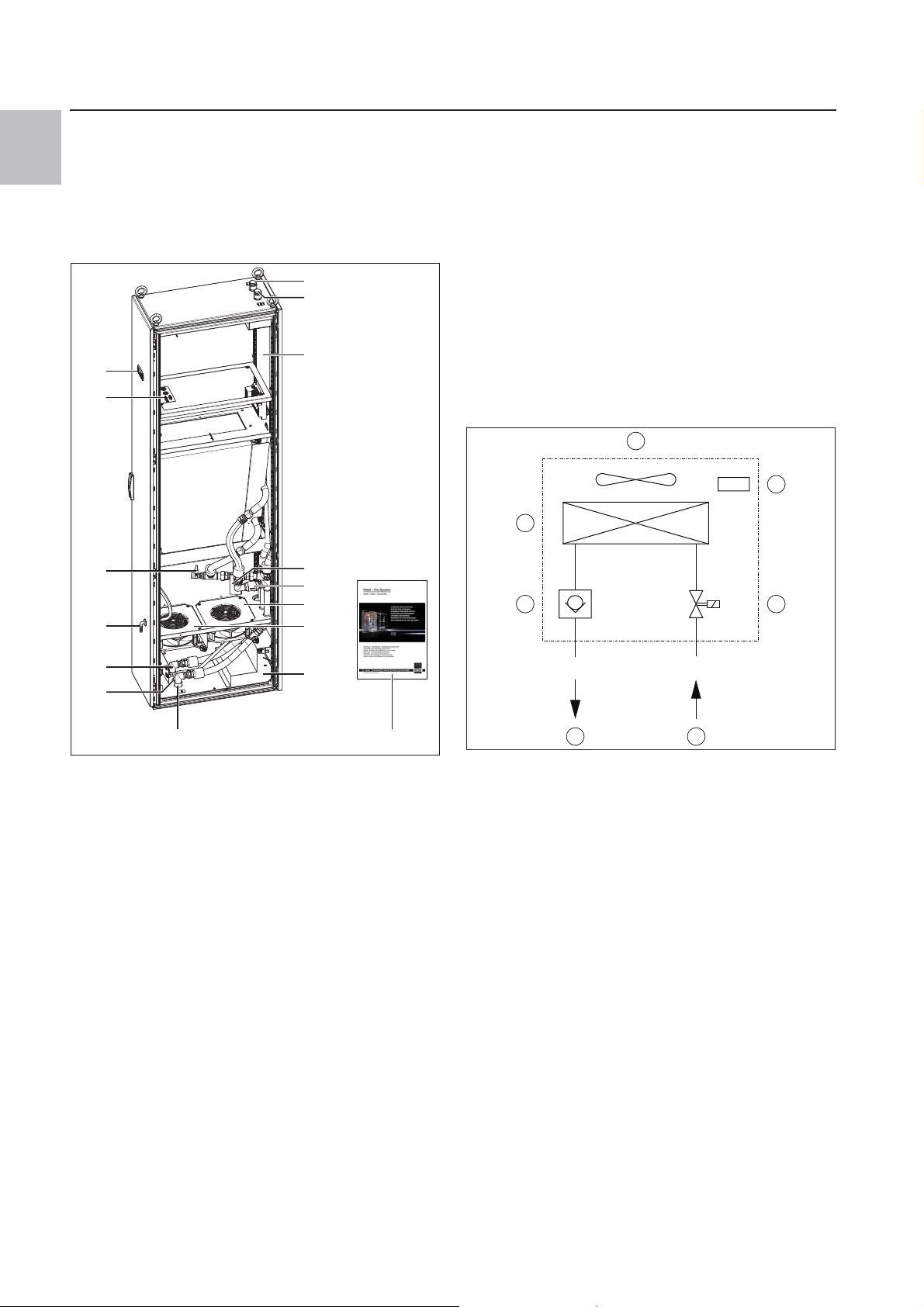
Fig. 1: Device description
Key
1 Water inlet, top
2 Water outlet, top
3 Gland for cables and busbars, top
4Magnetic valve
5Non-return valve
6Fan
7 Gland for cables and busbars, bottom (PE and N)
8 Water inlet, bottom
Water outlet
9 Condensate overflow
Water inlet,
10 Water outlet, bottom
11 Condensate water discharge
12 Drain cock
13 Cable entry
14 Display
15 Assembly and operating instructions
7
158
3.2 Functional description
Air/water heat exchangers are designed and built to dissipate heat from enclosures by cooling the air inside the
enclosure and so protect the temperature-sensitive
components.
Air/water heat exchangers are particularly appropriate
for the temperature range of +5°C to +70°C where com-
17 16
Fig. 2: Air/water heat exchanger
Key
1Non-return valve
2 Heat exchanger
3Fan
4 Temperature control
5Magnetic valve
6 Cooling water inlet
7 Cooling water return
The heat loss of the enclosure is dissipated in a membrane heat exchanger to the water coolant. A fan
(item 3) blows the internal enclosure air over the heat exchanger (item 2); except for the inlet and outlet water
and the condensed water discharge, the unit is closed
to the environment.
The magnetic valve (item 5) controls the cooling output
by changing the water flow volume depending on the required target temperature and the water inlet temperature.
6 Rittal air/water heat exchanger
3 Device description
3.2.2 Control
Rittal air/water heat exchangers are fitted with an
e-Comfort controller for setting the functions of the heat
exchanger.
3.2.3 Bus mode
The serial interface X2 allows you to create a bus connection with up to ten air/water heat exchangers using
the master-slave cable (shielded, four-wire cable, Model
No. 3124.100).
This allows you to implement the following functions:
– Parallel unit control (the air/water heat exchangers in
the network can be switched on and off simultaneous-
ly)
– Parallel door status message ("door open")
– Parallel collective fault message
Data is exchanged via the master-slave connection.
During commissioning, assign an address to each unit
that also includes the identifier "master” or "slave” (see
section 6.9 "Setting the master-slave identifier").
3.2.4 Safety equipment
– The EC fan is protected against overcurrent and over-
temperature by the integral electronics.
– The device has two integral floating contacts on the
terminal block 3 – 5, via which system messages from
the heat exchanger may be polled e.g. via a PLC (2 x
normally-open contacts).
– The air/water heat exchanger has a leak and conden-
sate warning. The device also has an overflow via its
base.
3.2.5 Condensation
At high levels of humidity and low cooling water temperatures inside the enclosure, condensation may form on
the heat exchanger.
Any condensation that forms on the heat exchanger
(with high humidity and low water temperatures) is routed to the front out of the unit via a drain opening in the
heat exchanger tray. For this purpose, a hose must be
connected to the condensate nozzle (see section 4.3.3
"Connecting the condensate discharge"). The condensate must be able to run off freely. The hose used for
draining off condensate must be laid free from kinks and
checked for correct drainage. Condensate hoses are
available as accessories (refer also to the accessories
section in the Rittal Catalogue).
3.2.6 Leak detection
If a leakage or pipe breakage occurs in the water circuit
of the air/water heat exchanger, a magnetic valve immediately stops the cooling water supply, the floating
change-over contact activated and the fan switched off.
The warning "A08" appears on the display.
3.2.7 Door limit switch
The air/water heat exchanger may be operated with a
door limit switch connected. The door limit switch is not
included with the supply (available as an accessory,
Model No. 4127.010).
The door limit switch function causes the fan and the
magnetic valve in the air/water heat exchanger to be
switched off after approximately 15 seconds when the
enclosure door is opened (contacts 1 and 2 closed). This
prevents the formation of condensation inside the enclosure while the enclosure door is open.
The fan will start up after about 15 seconds on closure
of the door. The connection is made at terminals 1 and
2. The extra-low voltage is supplied by the internal power pack; the current is approx. 30 mA DC.
Note:
The door limit switches must only be con-
nected free from potential. No external voltages!
3.2.8 Additional interface X3
Note:
The electrical signals at the interface are of an
extra-low voltage (not extra-low safety voltages to EN 60 335).
An additional interface board may be connected to the
9-pole SUB-D connector X3 in order to incorporate the
air/water heat exchanger into higher-level monitoring
systems (available as an accessory, interface board
Model No. 3124.200).
3.3 Proper use
Rittal enclosure air/water heat exchangers were developed and designed in accordance with the state of the
art and the recognised rules governing technical safety.
Nevertheless, if used improperly, they may pose a threat
to life and limb or cause damage to property. The unit is
only intended for cooling enclosures. Any other use is
deemed improper. The manufacturer will not be liable for
any damages caused as a result of improper use, or for
incorrect assembly, installation or use.
All risk is borne solely by the user. Proper usage also includes the observation of all valid documents and compliance with the inspection and servicing conditions.
3.4 Scope of supply
The unit is supplied in a packaging unit in a fully
assembled state.
Please check the delivery for completeness:
Qty. Description
1 Air/water heat exchanger
1 Dispatch bag:
1 – Assembly and operating instructions
Tab. 1: Scope of supply
EN
Rittal air/water heat exchanger 7
4 Installation
EN
4 Installation
4.1 Safety instructions
Warning!
Please note the maximum weights that
may be lifted by individuals. It may be
necessary to use lifting gear.
Warning!
Work on electrical systems or equip-
ment may only be carried out by an electrician or by trained personnel under the
guidance and supervision of an electrician.
The air/water heat exchanger may only
be connected after the aforementioned
personnel have read this information!
Use only insulated tools.
Follow the connection regulations of the
appropriate electrical supply company.
4.3 Assembly procedure
4.3.1 Assembly instructions
Check the packaging carefully for signs of damage.
Packaging damage may be the cause of a subsequent
functional failure.
– The enclosure must be sealed on all sides (IP 54). In-
creased condensation will occur if the enclosure is not
airtight.
– The air inlet and outlet must not be obstructed on the
inside of the enclosure.
When arranging the components inside the enclosure,
please ensure that the cold airflow from the air/water
heat exchanger is not directed at active components.
The air/water heat exchanger must be
connected to the mains via an all-pin
isolating device to overvoltage categoryIII (IEC 61 058-1).
The air/water heat exchanger is not deenergised until all of the voltage sources
have been disconnected!
4.2 Siting location requirements
When choosing the installation site for the enclosure,
please observe the following:
– The air/water heat exchanger must be installed and
operated in a vertical position.
– The ambient temperature must not exceed +70°C.
– It must be possible to fit a condensate discharge (see
section4.3.3 "Connecting the condensate dis-
charge").
– It must be possible to fit a cooling water supply and re-
turn (see section 4.4 "Connecting the water connec-
tion").
– The mains connection data as stated on the rating
plate of the unit must be guaranteed.
– Clearance of at least 1 m must be left in front of the
door to guarantee convenient access in case of servic-
ing.
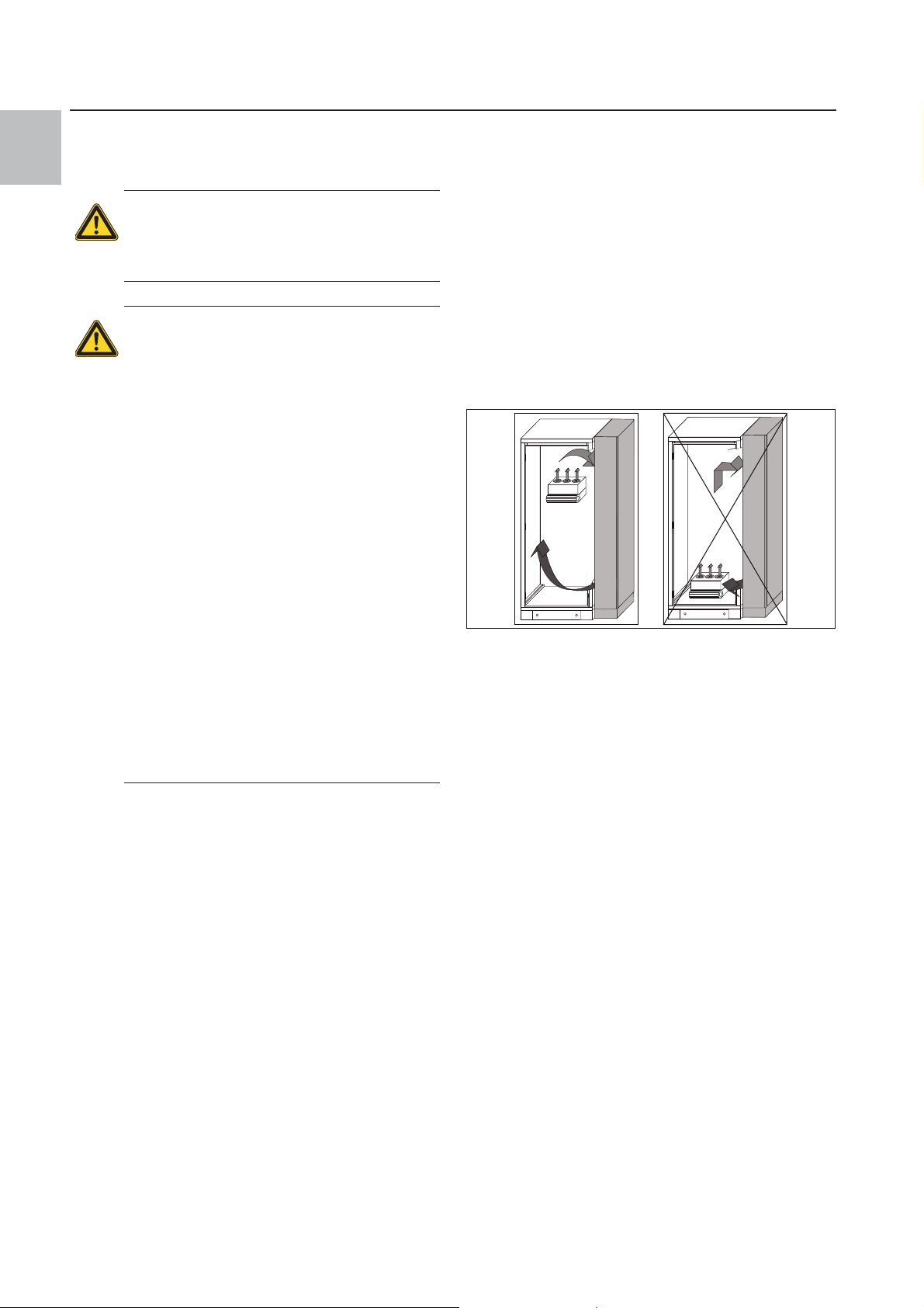
Fig. 3: Never direct the cold airflow at active components
Please also ensure that the cold airflow is not directed
at the warm exhaust airflow from active components
such as converters.
This may lead to an air short-circuit and therefore prevent adequate climate control, or may even cause the
air/water heat exchanger's internal safety devices to
cease cooling operation.
Exercise particular caution with the airflow from the
blowers of built-in electronic components (fig. 3).
Never site the air/water heat exchanger directly adjacent to the mounting plate.
If such installation is unavoidable, appropriate measures must be taken to optimise the air routing.
It is important to ensure even air circulation inside the
enclosure.
Under no circumstances should air inlet and outlet
openings be obstructed, otherwise the cooling performance of the unit will be reduced.
Ensure a suitable distance from electronic components and other installed enclosures so that the required air circulation is not obstructed and prevented.
8 Rittal air/water heat exchanger
4 Installation
20˚ C
200
Fig. 4: Targeted air routing inside the enclosure
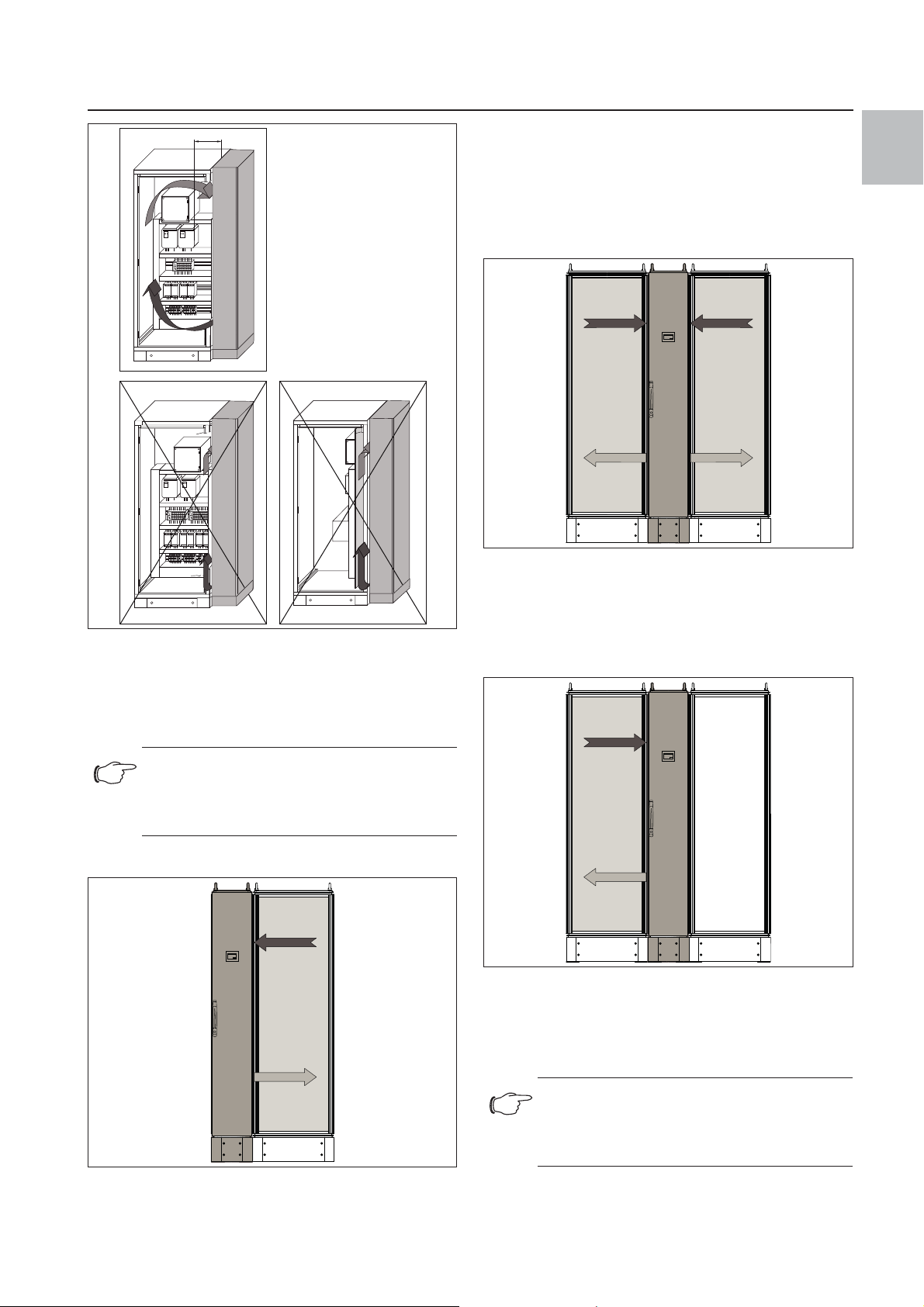
4.3.2 Mounting options
The air/water heat exchanger enclosure can be placed
either within or to the right or left of an existing TS 8 enclosure suite (observe TS 8 dimensions!).
If the air/water heat exchanger is bayed on the left or
right, the left side or right side of the air/water heat exchanger (as appropriate) must be sealed with a side
panel for TS 8 enclosure systems (Model No. 8106.235
for SK 3378.200 or 8108.235 for SK 3378.280).
Baying in the middle of an enclosure suite
20˚ C
Fig. 6: Baying in the middle of an enclosure suite
In case of installation within an enclosure suite, it is not
necessary to seal the air/water heat exchanger to the left
or right.
Baying between two TS 8 enclosures
EN
Note:
Use the assembly parts included with the
Rittal system accessories to ensure secure
baying.
Baying on the left or right
20˚ C
Fig. 5: Baying on the left or right
Fig. 7: Baying between two TS 8 enclosures
If the air/water heat exchanger is placed between two
TS 8 enclosures, but cooling is only required on one
side, the air inlet opening can be closed with an optional
metal cover.
Note:
The enclosure must be sealed on all sides. In
particular, in the area of the cable inlet openings and the enclosure base.
Rittal air/water heat exchanger 9
4 Installation
1
EN
Note:
The air/water heat exchanger may be fitted
on a base/plinth system (refer also to Accessories in the Rittal Catalogue).
4.3.3 Connecting the condensate discharge
A flexible condensate hose, dia. 12 mm (½"), can be fitted to the air/water heat exchanger to drain any condensate into a collecting bottle.
The condensate discharge
– must be laid with a suitable and constant gradient (no
siphoning),
– must be laid without kinks and
– must not have a reduced cross-section if extended.
The condensate hose (3301.612), condensate collecting bottle (3301.600) and external condensate evaporator (3301.500 or 3301.505) are available as accessories
(see also Accessories in the Rittal Catalogue).
1
2
3
Fig. 9: Removing the sealing caps at the top
Key
1 Water inlet, top
2 Open-jawed spanner
3 Water outlet, top
Fig. 8: Connecting the condensate discharge
Key
1 Connecting the condensate discharge
Connect a suitable hose to the condensate nozzle (at
the bottom of the door) and secure it with a hose clip
(with 2 Nm torque).
Lay the condensate hose, e.g. into a drain.
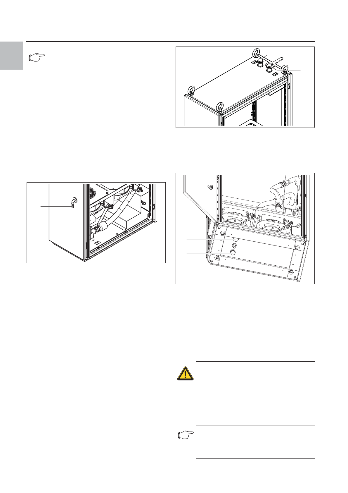
4.4 Connecting the water connection
The water hoses may optionally be connected to the top
or bottom of the device (¾" internal thread).
First, remove the sealing caps using an SW 22 open-
jawed spanner.
1
2
Fig. 10: Removing the sealing caps at the bottom
Key
1 Water inlet, bottom
Water outlet,
2 Water outlet, bottom
Water inlet,
The cooling water hose
– must be laid without kinks
– must not have a reduced cross-section if extended
and
– if necessary, must be insulated.
Warning!
Switch off the power supply to the air/
water heat exchanger before opening
the electrical connection box and before
working on the water circuit, and take
suitable precautions against it being accidentally switched on again.
Note:
The water inlet temperature should be selected to prevent the formation of critical condensation in the enclosure being cooled.
10 Rittal air/water heat exchanger
 Loading...