

Rittal SK 3302.100, SK 3302.110, SK 3303.100, SK 3303.110, SK 3302.200 Assembly And Operating Instructions Manual
...
Montage-, Installations- und Bedienungsanleitung
Assembly and operating instructions
Manuel d’installation et de maintenance
Montage- en bedieningshandleiding
Montage- och hanteringsanvisning
Istruzioni di montaggio e funzionamento
Instrucciones de montaje
R
SchaltschrankKühlgerät
Cooling unit
Climatiseur
Koelaggregaat
Kylaggregat
Condizionatori per
armadi di comando
Refrigerador
para armarios
SK 3302.xxx
SK 3302.3xx
SK 3303.xxx
SK 3304.xxx
SK 3305.xxx
SK 3328.xxx
SK 3329.xxx
SK 3332.xxx
SK 3361.xxx
SK 3366.xxx
SK 3377.xxx


RITTAL cooling unit assembly and operating instructions 3
EN
Contents
1 Notes on documentation. . . . . . . . . . 4
1.1 Associated documents. . . . . . . . . . . . . . . . . 4
1.2 CE labelling . . . . . . . . . . . . . . . . . . . . . . . . . . 4
1.3 Retention of documents. . . . . . . . . . . . . . . . 4
1.4 Symbols used . . . . . . . . . . . . . . . . . . . . . . . . 4
2 Safety instructions. . . . . . . . . . . . . . . 4
3 Device description. . . . . . . . . . . . . . . 5
3.1 Functional description . . . . . . . . . . . . . . . . . 5
3.1.1 How it works . . . . . . . . . . . . . . . . . . . . . . . . . . 5
3.1.2 Control. . . . . . . . . . . . . . . . . . . . . . . . . . . . . . . 5
3.1.3 Bus mode (Comfort controller only) . . . . . . . . 5
3.1.4 Safety equipment . . . . . . . . . . . . . . . . . . . . . . 6
3.1.5 Condensation . . . . . . . . . . . . . . . . . . . . . . . . . 6
3.1.6 Filter mats . . . . . . . . . . . . . . . . . . . . . . . . . . . . 6
3.1.7 Door limit switch . . . . . . . . . . . . . . . . . . . . . . . 6
3.1.8 Additional interface X3 . . . . . . . . . . . . . . . . . . 7
3.2 Proper usage . . . . . . . . . . . . . . . . . . . . . . . . . 7
3.3 Scope of supply . . . . . . . . . . . . . . . . . . . . . . 7
4 Assembly and connection . . . . . . . . 7
4.1 Choosing the installation site . . . . . . . . . . . 7
4.2 Assembly instructions . . . . . . . . . . . . . . . . . 7
4.2.1 General . . . . . . . . . . . . . . . . . . . . . . . . . . . . . . 7
4.2.2 Layout of the electronic components
in the enclosure. . . . . . . . . . . . . . . . . . . . . . . . 8
4.3 Fitting the cooling unit . . . . . . . . . . . . . . . . . 8
4.3.1 Cutting out the enclosure . . . . . . . . . . . . . . . . 9
4.3.2 External mounting of the cooling unit . . . . . . . 9
4.3.3 Partial internal mounting
of the cooling unit . . . . . . . . . . . . . . . . . . . . . . 9
4.3.4 Full internal mounting of the cooling unit . . . 11
4.4 Connecting the condensate discharge. . . 11
4.5 Notes on electrical installation . . . . . . . . . 12
4.5.1 Connection data . . . . . . . . . . . . . . . . . . . . . . 12
4.5.2
Overvoltage protection
and supply line load
. . . . . . . . . . . . . . . . . . . 12
4.5.3 Three-phase devices . . . . . . . . . . . . . . . . . . 12
4.5.4 Door limit switch . . . . . . . . . . . . . . . . . . . . . . 12
4.5.5 Notes on the flicker standard . . . . . . . . . . . . 12
4.5.6 Potential equalisation . . . . . . . . . . . . . . . . . . 12
4.6 Carrying out the electrical installation . . . 13
4.6.1 Bus connection
(only in conjunction with several units with
a Comfort controller) . . . . . . . . . . . . . . . . . . . 13
4.6.2 Connection X3 for serial interface. . . . . . . . . 13
4.6.3 Installing the power supply. . . . . . . . . . . . . . 14
4.7 Finalising assembly . . . . . . . . . . . . . . . . . . 22
4.7.1 Installing the filter media . . . . . . . . . . . . . . . 22
4.7.2 Fitting the cooling unit. . . . . . . . . . . . . . . . . . 22
4.7.3 Setting the filter mat monitor
(only with Comfort controller) . . . . . . . . . . . . 22
5 Commissioning . . . . . . . . . . . . . . . . 22
6 Operation . . . . . . . . . . . . . . . . . . . . . 23
6.1 Control using the Basic controller . . . . . . 23
6.1.1 Properties. . . . . . . . . . . . . . . . . . . . . . . . . . . .23
6.1.2 Operating and error display. . . . . . . . . . . . . .24
6.1.3 Test mode for the Basic controller . . . . . . . . .25
6.1.4 Setting the temperature . . . . . . . . . . . . . . . . .25
6.1.5 Resetting the Basic controller . . . . . . . . . . . .25
6.2 Control using the Comfort controller . . . . 26
6.2.1 Properties. . . . . . . . . . . . . . . . . . . . . . . . . . . .26
6.2.2 Launching test mode . . . . . . . . . . . . . . . . . . .26
6.2.3 General programming information. . . . . . . . .26
6.2.4 Editable parameters. . . . . . . . . . . . . . . . . . . .27
6.2.5 Programming overview . . . . . . . . . . . . . . . . .28
6.2.6 Defining system messages
for evaluation . . . . . . . . . . . . . . . . . . . . . . . . .29
6.2.7 Setting the master-slave identifier . . . . . . . . .30
6.2.8 Evaluating system messages. . . . . . . . . . . . .30
6.2.9 Resetting the Comfort controller . . . . . . . . . .32
7 Inspection and maintenance. . . . . . 32
7.1 General . . . . . . . . . . . . . . . . . . . . . . . . . . . . 32
7.1.1 Compressed air cleaning
SK 3304.xxx, SK 3305.xxx . . . . . . . . . . . . . . .32
7.1.2 Compressed air cleaning
SK 3328.xxx, SK 3329.xxx, SK 3332.xxx . . . .36
8 Storage and disposal. . . . . . . . . . . . 41
9 Technical specifications . . . . . . . . . 41
10 List of spare parts . . . . . . . . . . . . . . 45
11 Appendix:
Cut-out and hole sizes
. . . . . . . . . . . 49
11.1 Dimensions for external mounting . . . . . . 49
11.2 Dimensions for partial
internal mounting . . . . . . . . . . . . . . . . . . . . 50
11.3 Dimensions for full internal mounting . . . 51
4 RITTAL cooling unit assembly and operating instructions
1 Notes on documentation
EN
1 Notes on documentation
These assembly instructions are aimed at tradespersons who are familiar with assembly and installation
of the cooling unit, and at trained specialists who are
familiar with operation of the cooling unit.
1.1 Associated documents
There are two sets of instructions for the unit types
described here:
– Assembly and installation instructions enclosed
with the unit in the form of a paper document
– Assembly, installation and operating instructions
enclosed with the unit in the form of a PDF file
(Adobe Acrobat) on CD-ROM
We cannot accept any liability for damage associated with failure to observe these instructions. Where
applicable, the instructions for any accessories used
also apply.
1.2 CE labelling
The declaration of conformity is supplied with the unit
as a separate document.
1.3 Retention of documents
These instructions and all associated documents
constitute an integral part of the product. They must
be given to the plant operator. The plant operator is
responsible for storage of the documents so they are
readily available when needed.
1.4 Symbols used
Please observe the following safety instructions and
other notes in this guide:
Symbol for an instructed action:
• The bullet point indicates that you should perform
an action.
Safety and other instructions:
2 Safety instructions
Please observe the following general safety instructions when assembling and operating the unit:
– Assembly, installation and servicing may only be
performed by properly trained specialists.
– Screw the enclosure to the floor to prevent it from
tipping over when the cooling unit is installed.
– Do not obstruct the air inlet and air outlet of the
cooling unit inside and outside the enclosure
(see also section 4.2.2).
– To ensure problem-free opening and closing of
the enclosure door, use a ride-up door roller (refer
to the accessories in the RITTAL Catalogue).
This raises the door slightly and balances out the
weight of the cooling unit, to prevent buckling of
the door and associated seal problems.
– The heat loss of the components installed in the
enclosure must not exceed the specific useful
cooling output of the cooling unit.
– When transporting the enclosure with the cooling
unit externally mounted, always use an additional
shipping brace to support the cooling unit.
– The cooling unit must always be transported in an
upright position.
– Use only original spare parts and accessories.
– Do not make any changes to the cooling unit other
than those described in these instructions or asso-
ciated instructions.
– Risk of burn injuries! For cooling units with auto-
matic condensate evaporation, the surface of the
thermal element will get very hot during operation,
and will remain so for some time afterwards.
– The mains connector of the cooling unit must only
be connected and disconnected with the system
de-energised. Connect the pre-fuse specified on
the rating plate.
Danger!
Immediate danger to life and limb!
Caution!
Potential threat to the product
and its environment.
Note:
Useful information
and special features.
3 Device description
RITTAL cooling unit assembly and operating instructions 5
EN
3 Device description
Depending on the model chosen, your cooling unit
may vary in appearance from the illustrations contained in these instructions. However, the functions
are identical in principle.
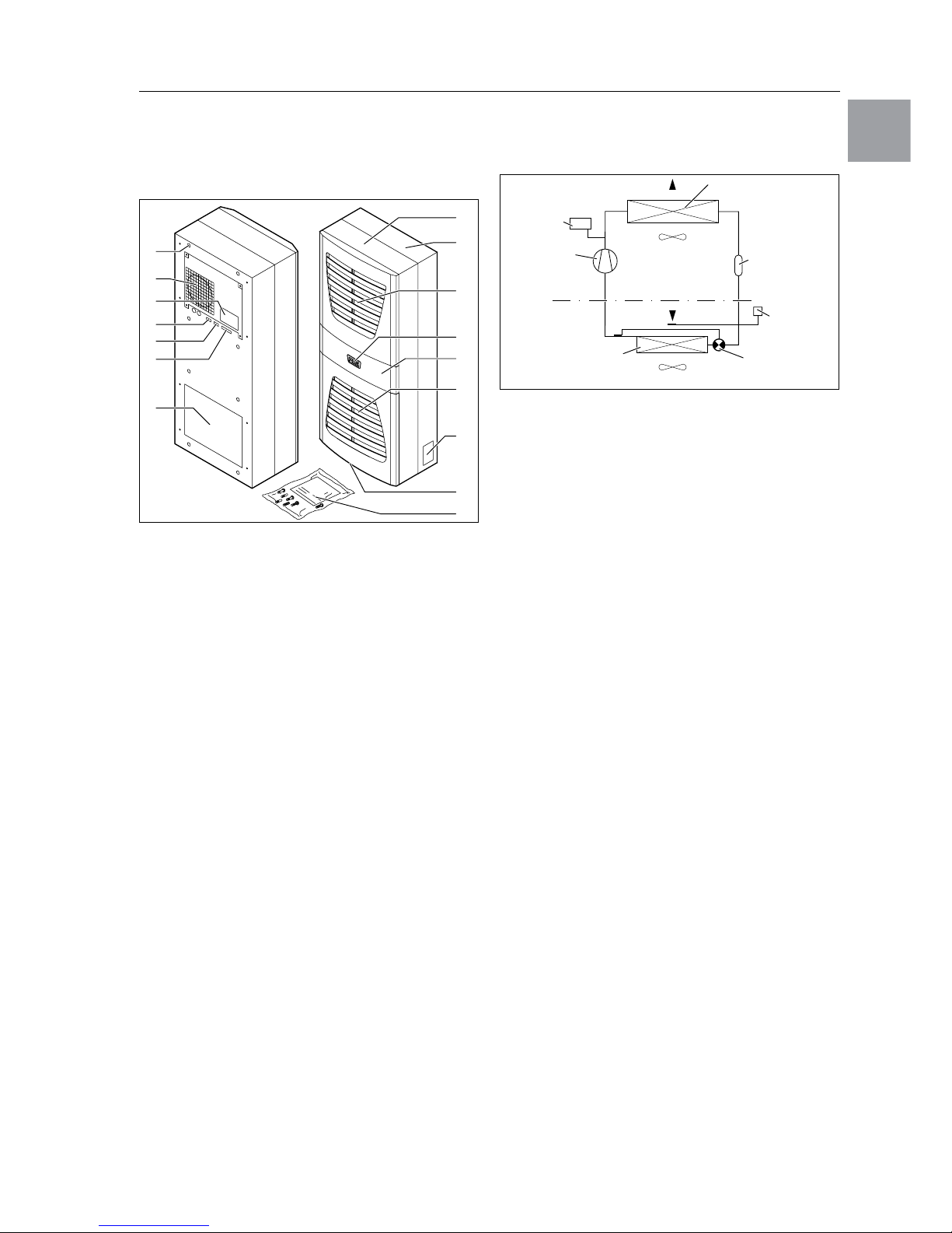
Fig. 1: Device description
Legend
1 Blind nut
2 Evaporator fan
3 Electrical wiring plan
4 X2 master-slave connection
5 X3 optional serial interface
6 X1 terminal strip
7 Air outlet hole
8 Front half of the enclosure
9 Rear half of the enclosure
10 Louvred grille for air outlet
11 Display
12 Infill panel
13 Louvred grille for air inlet
14 Rating plate
15 Condensate discharge
16 Dispatch bag
3.1 Functional description
Enclosure cooling units are designed to dissipate
heat from enclosures by cooling the air inside the
enclosure and so protect the temperature-sensitive
components. They are built into the side or rear
panel or into the door of the enclosure.
3.1.1 How it works
The cooling unit (compression refrigeration system)
is comprised of four main components (cf. Fig. 2):
the evaporator (1), the coolant compressor (2), the
condenser (3), and the control or expansion valve
(4), which are connected by suitable pipework. This
circuit is filled with a readily boiling substance, the
refrigerant. Coolant R134a (CH
2
FCF3) is chlorinefree. Its ozone destruction potential is 0, making it
very eco-friendly. A filter dryer (5) which is integrated
into the hermetically sealed cooling circuit provides
effective protection against moisture, acid, dirt
particles, and foreign bodies within the cooling
circuit.
Fig. 2: Cooling circuit
In the evaporator coil (1), the liquid coolant is converted to a gaseous state. The energy needed for
this purpose is taken from the enclosure air in the
form of heat, which has the effect of cooling the
enclosure air. In the compressor (2), the coolant is
heavily compressed, so that it achieves a higher
temperature inside the condenser (3) than the ambient air. This means that excess heat may be emitted
to the ambient air via the surface of the condenser,
as a result of which the temperature of the coolant
drops and it is converted back into liquid. It is reinjected into the evaporator coil via a thermostatic
expansion valve (4), which causes it to cool down
further, and is then once again able to absorb the
energy from the enclosure air in the evaporator coil.
The whole cycle begins again.
3.1.2 Control
RITTAL enclosure cooling units are fitted with a controller for setting the functions of the cooling unit.
Depending on the design, this is either a Basic controller (display of the operating status via LED) or a
Comfort controller (display plus extended functions,
see chapter “6 Operation”, page 23).
3.1.3 Bus mode (Comfort controller only)
The serial unit interface X2 allows you to create a bus
connection with up to ten cooling units using the
master-slave cable (shielded, four-wire cable, Model
No. SK 3124.100). This allows you to implement the
following functions:
– Parallel unit control (the cooling units in the network
can be switched on and off simultaneously)
– Parallel door status message (“door open”)
– Parallel collective fault message
Data is exchanged via the master-slave connection.
During commissioning, assign an address to each
unit that also includes the identifier “master” or
“slave”.
10
9
8
11
13
12
16
15
14
1
2
4
5
6
7
3
PSA
H
pressure-
operated
switch
Condenser fan
Expansion valve (4)
Temperature
control
Filter dryer (5)
Internal circuit
Compressor
(2)
External circuit
Evaporator fan
Evaporator coil (1)
Condenser (3)

6 RITTAL cooling unit assembly and operating instructions
3 Device description
EN
3.1.4 Safety equipment
– In the cooling cycle, the cooling unit has a tested
pressure-operated switch to EN 12 263 which is
set to maximum PS (admissible pressure); this
operates via an automatic reset device whenever
the pressure drops again.
– Temperature monitoring prevents the evaporator
coil from icing over. If there is a risk of icing, the
compressor switches itself off and automatically
switches itself back on again at higher temperatures.
– The refrigerant compressor and the fans are
equipped with thermal winding shields to protect
against excess current and excess temperatures.
– In order to allow a reduction of pressure inside the
compressor and hence a safe restart, once it has
been switched off (e.g. upon reaching the set temperature via the door limit switch function or via deenergising), the device will switch back on with a
delay of 180 seconds.
– The device has floating contacts on the connection
pins (terminals 3 – 5), via which system messages
from the device may be polled, e.g. using a PLC
(1x change-over contact Basic controller, 2 x normally open contacts Comfort controller).
3.1.5 Condensation
At high levels of humidity and low temperatures inside the enclosure, condensation may form on the
evaporator coil.
The cooling units (except SK 3302.xxx, SK 3303.xxx
and SK 3361.xxx) have automatic, electric condensate evaporation. The thermal component used for
this purpose is based on self-regulating PTC technology. Condensate arising on the evaporator coil
is collected in a tank in the external circuit of the cooling unit, and partially evaporated via the airflow.
When the water level rises, the water enters the PTC
thermal component and is evaporated (through-flow
heater principle). The water vapour streams out of
the cooling unit with the airflow from the external fan.
The PTC thermal component is permanently connected and has no switchpoint. It is protected
against short-circuits with miniature fuses (F1.1,
F1.2). If the fuse has tripped, any condensation is
drained off via the safety overflow.
For unit types SK 3302.xxx, SK 3303.xxx and
SK 3361.xxx, the condensation is routed downwards
out of the unit via a drain pipe on the evaporator coil
divider panel. For this purpose, a hose must be connected to the condensate nozzle (see “4.4 Connecting the condensate drain”, page 11). External condensate evaporators are available as accessories
for these unit types (refer also to the accessories in
the RITTAL Catalogue).
3.1.6 Filter mats
The cooling unit condenser is finished all over with a
dirt-repelling, easy-to-clean RiNano coating. In many
cases, therefore, the use of filter media is unnecessary, particularly in the case of dry dusts.
For dry, coarse dust and lint in the ambient air, we
recommend installing an additional PU foam filter
mat (available as an accessory) in the cooling unit.
Depending on the incidence of dust, you will need
to replace the filter from time to time.
For air containing oil condensation, we recommend
the use of metal filters (also available as an accessory). These may be cleaned with suitable detergents
and reused.
Function of the filter mat monitor:
Dirt on the filter mat is automatically determined by
measuring the temperature difference in the external
circuit of the cooling unit. As the level of filter mat soiling rises, the temperature difference will increase.
The nominal value of the temperature difference in
the external circuit adapts automatically to the relevant operating points in the performance diagrams.
Hence there is no need to readjust the nominal value
for different operating points of the cooling unit.
3.1.7 Door limit switch
The cooling unit may be operated with a floating door
limit switch connected. The door limit switch is not included with the supply (available as an accessory,
Model No. PS 4127.000).
The door limit switch function causes the fans and
the compressor in the cooling unit to be switched off
after approximately 15 seconds when the enclosure
door is opened (contacts 1 and 2 closed). This prevents the formation of condensation inside the enclosure while the enclosure door is open. In order to
prevent damage to the unit, it is equipped with an
ON delay: The evaporator fan cuts back in with a delay of approximately 15 seconds after the door has
been closed, while the condenser fan and compressor switch on after approximately 3 minutes.
Note:
– No external voltage must be applied to
the door contacts (terminals 1 and 2).
– For Basic controller cooling units with
230/115 V and 400 V/2-phase connection, the evaporator fan remains operational even with the door open.
4 Assembly and connection
RITTAL cooling unit assembly and operating instructions 7
EN
3.1.8 Additional interface X3
An additional interface card may be connected to
the 9-pole SUB-D connector X3 in order to incorporate the cooling unit into higher-level monitoring
systems (available as an accessory, interface card
Model No. SK 324.200).
3.2 Proper usage
RITTAL enclosure cooling units were developed and
designed in accordance with the state-of-the-art and
the recognised rules governing technical safety.
Nevertheless, if used improperly, they may pose a
threat to life and limb or cause damage to property.
The unit is only intended for cooling enclosures. Any
other use is deemed improper. The manufacturer will
not be liable for any damages caused as a result of
improper use, or for incorrect assembly, installation
or use. All risk is borne solely by the user.
Proper usage also includes the observation of all
valid documents and compliance with the inspection
and servicing conditions.
3.3 Scope of supply
The unit is supplied in a packaging unit in a fully
assembled state.
Please check the delivery for completeness:
Tab. 1: Scope of supply
4 Assembly and connection
4.1 Choosing the installation site
When choosing the installation site for the enclosure,
please observe the following:
– The site for the enclosure, and hence the arrange-
ment of the cooling unit, must be carefully selected
so as to ensure good ventilation (distances bet-
ween units and distances between the unit and the
wall must be at least 200 mm in each case).
– The cooling unit must be installed and operated in
a vertical position (maximum deviation: 2°).
– The site must be free from excessive dirt and
moisture.
– The ambient temperature must not exceed 55°C.
– It must be possible to fit a condensate discharge
(see “4.4 Connecting the condensate discharge”,
page 11).
– The mains connection data as stated on the rating
plate of the unit must be guaranteed.
4.2 Assembly instructions
4.2.1 General
– Check the packaging carefully for signs of damage.
Traces of oil on damaged packaging are an indi-
cation of refrigerant loss and leakages. Packaging
damage may be the cause of a subsequent func-
tional failure.
– The enclosure must be sealed on all sides (IP 54).
Increased condensation will occur if the enclosure
is not airtight.
– In order to avoid excessive condensation inside
the enclosure, we recommend installing a door
limit switch (e.g. PS 4127.000) which deactivates
the cooling unit when the enclosure door is opened
(see “3.1.7 Door limit switch”, page 6).
Note:
The electrical signals at the interface are of
an extra-low voltage (not extra-low safety
voltages to EN 60 335).
Qty.
Description
1 Enclosure cooling unit
1
1
1
1
1
4 – 10
1
Dispatch bag:
– Assembly and installation instructions
– Assembly, installation and operating
instructions on CD-ROM
– Self-adhesive tape
– Connector X1
– Threaded rods
– Declaration of conformity
– Nuts, washers
1 Drilling template
8 RITTAL cooling unit assembly and operating instructions
4 Assembly and connection
EN
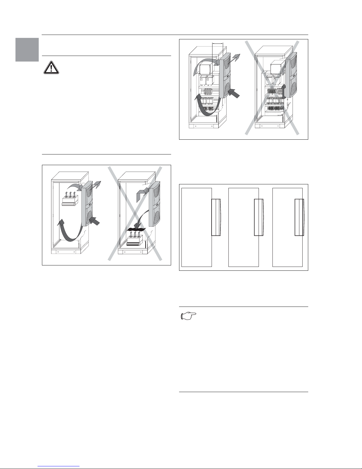
4.2.2 Layout of the electronic components
in the enclosure
Fig. 3: Never direct the cold airflow at active components
Air diversion components are available as accessories – please refer to the RITTAL catalogue “System
climate control”.
It is important to ensure even air circulation inside the
enclosure. Under no circumstances should air inlet
and outlet openings be obstructed, otherwise the
cooling performance of the unit will be reduced.
Ensure the distance “x” (see Fig. 4) from electronic
components and other installed enclosures so that
the required air circulation is not obstructed and prevented.
Fig. 4: Air circulation inside the enclosure
4.3 Fitting the cooling unit
The enclosure cooling unit may optionally be externally mounted on the enclosure (1), partially internally mounted (2) or fully internally mounted (3):
Fig. 5: Installation method
To this end, cut the side panel or door of the enclosure as per the drilling template included with the
supply, and drill the relevant holes.
Caution!
Risk of condensation!
When arranging the components inside
the enclosure, please ensure that the
cold airflow from the cooling unit is not
directed at active components. Please
also ensure that the cold airflow is not
directed at the warm exhaust airflow
from active components such as converters. This may lead to an air shortcircuit and therefore prevent adequate
climate control, or may even cause the
cooling unit’s internal safety devices to
cease cooling operation.
Note:
Units of type SK 3302.xxx can only be either
externally mounted or fully internally mounted.
Units of type SK 3332.xxx can only be either
externally mounted or partially internally
mounted.
For mounting the units SK 3328.xxx,
SK 3329.xxx and SK 3332.xxx in the TS side
panel or rear panel, we recommend the use
of enclosure panel fasteners TS 8800.071
(see RITTAL Catalogue).
x
1 2 3
4 Assembly and connection
RITTAL cooling unit assembly and operating instructions 9
EN
4.3.1 Cutting out the enclosure
• Stick the supplied drilling template onto the side
panel or door of the enclosure using adhesive
tape.
There are dimensioning lines on the drilling template
to suit the various installation options for your cooling
unit.
• Using the dimension drawings (see Appendix),
identify the valid lines and dimensions for your
installation type on the drilling template.
• Mark, drill and deburr the holes.
• Make the cut-outs including the line width as per
the drilling template.
Deburr the cut-outs.
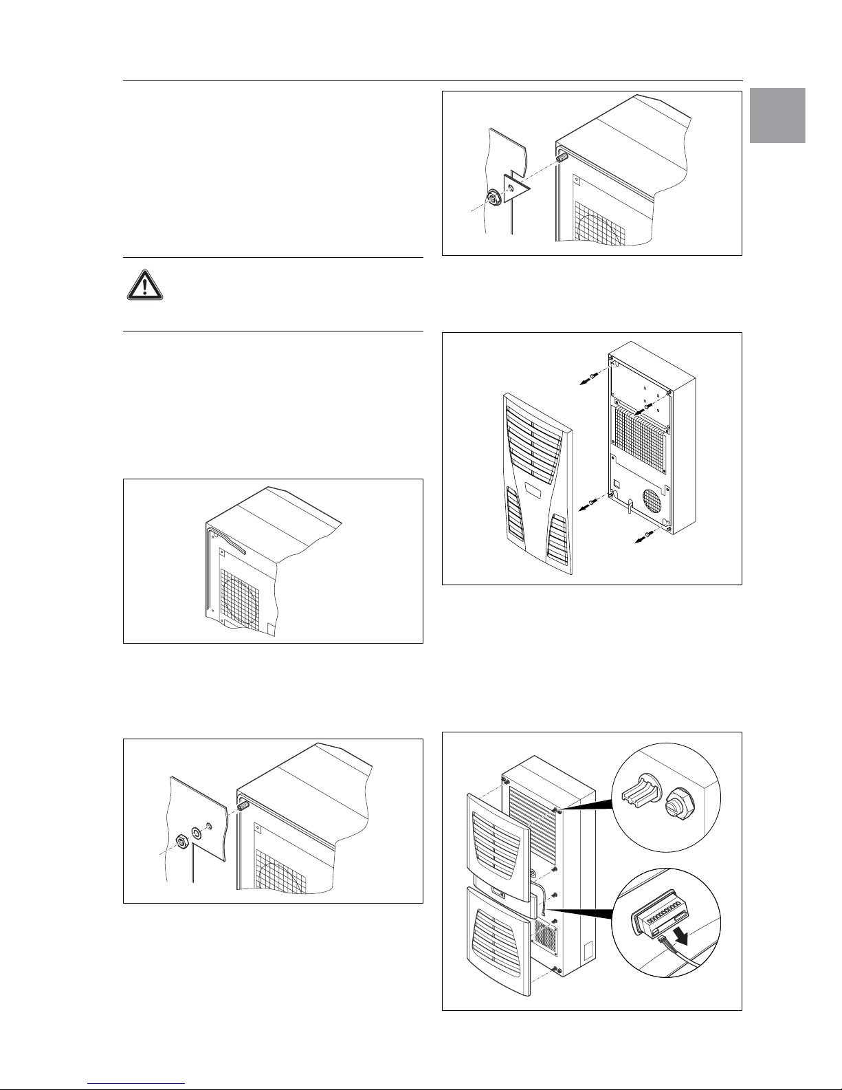
4.3.2 External mounting of the cooling unit
• Cut the supplied sealing tape to the correct length
and stick it carefully along the back of the unit so
that no gaps are left at the joints.
Fig. 6: Attach the sealing tape
• Screw the supplied grub screws into the blind nuts
on the rear of the unit.
• Secure the unit using the supplied washers and
nuts.
Fig. 7: Secure the cooling unit
(all models except SK 3302.1xx)
Fig. 8: Secure the cooling unit
(SK 3302.1xx “external mounting” only)
Only for SK 3302.xxx:
• Before installing, remove the four screws as shown.
Fig. 9: Only for SK 3302.xxx: Remove the four screws
4.3.3 Partial internal mounting of the cooling unit
• Carefully remove the louvred grille and, where
applicable, the infill panel, from the enclosure by
pulling forwards.
• Carefully disconnect the connector from the rear of
the display and gently push it inwards through the
cable gland.
Fig. 10: Remove the louvred grille & disconnect the display
Risk of injury!
Carefully deburr all drilled holes and
cut-outs to prevent injuries caused by
sharp edges.
4x
10 RITTAL cooling unit assembly and operating instructions
4 Assembly and connection
EN
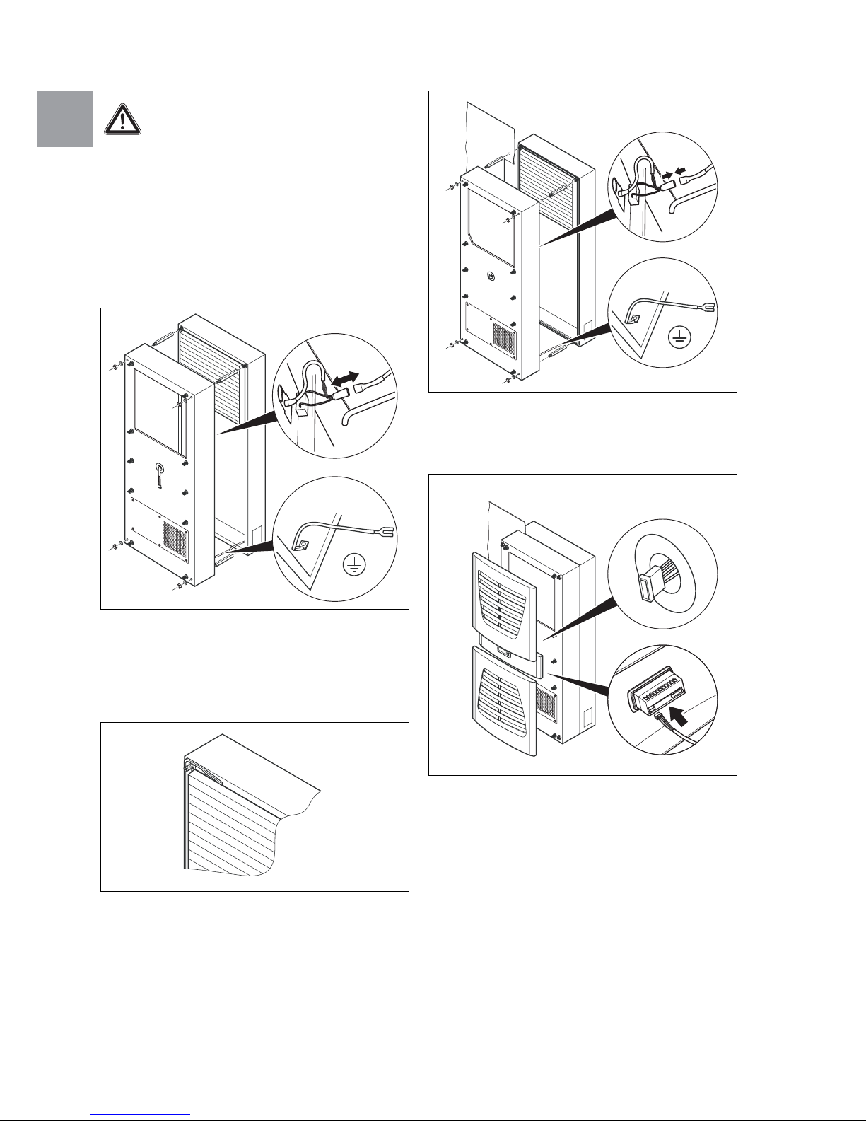
• Loosen the four nuts on the front enclosure half and
pull the enclosure forwards by approx. 5 cm.
• Loosen the flat-pin connectors of the PE conductor
between the two enclosure halves.
• Disconnect the fan connection.
• Remove the front enclosure tray completely.
Fig. 11: Remove the cover
• Remove the four spacer bolts.
• Cut the supplied sealing tape to the correct length
and stick it carefully along the inside of the rear
enclosure half so that no gaps are left at the connection points.
Fig. 12: Attach the sealing tape
• Push the rear enclosure half into the mounting cutout and secure it with the four spacer bolts.
• Push the display cable through the cable gland of
the front enclosure half.
Fig. 13: Secure the cooling unit
• Connect the fan connector and PE conductor.
• Mount the front enclosure tray using the washers
and nuts.
Fig. 14: Connect the display connector
• Carefully connect the display connector.
• Push the louvred grille and, where applicable,
the infill panel, onto the enclosure.
Risk of damage!
Stability of the cooling unit is only
guaranteed in its assembled state.
Brace the rear enclosure half to prevent
it from falling over before removing the
front enclosure half.
4 Assembly and connection
RITTAL cooling unit assembly and operating instructions 11
EN
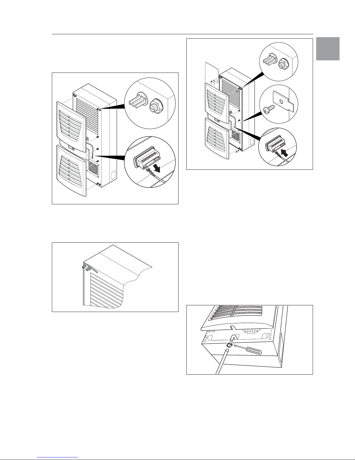
4.3.4 Full internal mounting of the cooling unit
• Carefully remove the louvred grille and the infill
panel from the enclosure by pulling forwards.
• Carefully disconnect the connector from the rear of
the display.
Fig. 15: Remove the louvred grille and disconnect
the display
• Cut the supplied sealing tape to the correct length
and stick it carefully along the front enclosure half
so that no gaps are left at the connection points.
Fig. 16: Attach the sealing tape
• Loosen the four nuts and washers from the front
enclosure half.
• Push the unit into the mounting cut-out from the
inside of the enclosure, and secure it to the enclosure from the outside using the washers and
nuts.
Fig. 17: Secure the cooling unit
• Where necessary, additionally secure the unit
using the supplied mounting plates as shown in
Fig. 17.
• Carefully connect the display connector.
• Push the louvred grille and, where applicable,
the infill panel, onto the enclosure.
4.4 Connecting the condensate discharge
Unit types SK 3302.xxx, SK 3303.xxx and
SK 3361.xxx support the installation of a condensate
discharge hose (Ø 1/2˝).
The condensate discharge
– must be laid with a suitable and constant gradient
(no siphoning)
– must be laid without kinks
– must not have a reduced cross-section if extended.
The condensate hose is available as an accessory
(refer also to Accessories in the RITTAL Catalogue).
Fig. 18: Connecting the condensate discharge
• Connect a suitable hose to the condensate nozzle
and secure using a hose clip.
• Lay the condensate hose into a pay-off or into the
external condensate evaporator (refer to accessories in the RITTAL Catalogue).

12 RITTAL cooling unit assembly and operating instructions
4 Assembly and connection
EN
4.5 Notes on electrical installation
When performing the electrical installation, it is important to observe all valid national and regional regulations as well as the provisions of the responsible
power supply company. Electrical installation must
only be carried out by a qualified electrician who is responsible for compliance with the existing standards
and regulations.
4.5.1 Connection data
– The connected voltage and frequency must
correspond to the values stated on the rating plate.
– The cooling unit must be connected to the mains
via an all-pin isolating device, which ensures at
least 3 mm contact opening when switched off.
– No additional temperature control may be connec-
ted upstream of the unit at the supply end.
– Install the pre-fuse specified on the rating plate
to protect the cable and equipment from shortcircuits.
– The mains connection must ensure low-noise
potential equalisation.
4.5.2 Overvoltage protection and supply line
load
– The unit does not have its own overvoltage pro-
tection. Measures must be taken by the operator at
the supply end to ensure effective lightning and
overvoltage protection. The mains voltage must not
exceed a tolerance of ±10%.
– In accordance with IEC 61 000-3-11, the unit is
intended solely for use at sites with a continuous
current-carrying capacity (incoming mains power
supply) of more than 100 A per phase and with
a supply voltage of 400/230 V. If necessary, the
power supply company must be consulted to
ensure that the continuous current-carrying capacity at the point of connection to the public grid is
sufficient for connection of such a unit.
– The fans and compressors in single- and three-
phase units are intrinsically safe (thermal winding
protection). The same also applies to the transformer versions of types SK 3304.110, SK 3304.510,
SK 3305.110, SK 3305.510, SK 3328.110,
SK 3328.510, SK 3329.110 and SK 3329.510
and to special-voltage units which are likewise
equipped with a transformer.
– Install the slow pre-fuse specified on the rating
plate (miniature circuit-breaker with “K” characteristic, circuit-breaker for plant or transformer
protection) to protect the cable and equipment from
short-circuits. Select a suitable circuit-breaker in
accordance with the information specified on the
rating plate: Set it to the minimum specified value.
This will achieve the best short-circuit protection for
cables and equipment.
Example: Specified setting range 6.3 – 10 A;
set to 6.3 A.
4.5.3 Three-phase devices
– The three-phase version of models SK 3304.xxx,
SK 3305.xxx, SK 3328.xxx, SK 3329.xxx and
SK 3332.xxx must be connected to a TN network
with star earthing via a circuit-breaker for plant
protection (current setting as per the rating plate).
Three-phase units with special voltages must be
protected with a circuit-breaker for transformer
protection (category AC-3) as per the rating plate.
– Units designed for three phase 400/460 V feature
additional monitoring of the rotary field or the
absence of a phase. If the rotary field is incorrect or
a phase is absent, the unit will not run.
4.5.4 Door limit switch
– Each door limit switch must only be assigned to one
cooling unit.
– Several door limit switches may be connected in
parallel and operated on one cooling unit.
– The minimum cross-section for the connection
cable is 0.3 mm2 for a cable length of 2 m.
– The line resistance to the door limit switch must not
exceed a maximum of 50 Ω.
– The door limit switch only supports a floating
connection; no external voltages.
– The contact of the door limit switch must be closed
when the door is open.
The safety extra-low voltage for the door limit switch
is
provided by the internal power pack: Current
approx. 30 mA DC.
• Connect the door limit switch to terminals 1 and 2 of
the connector.
4.5.5 Notes on the flicker standard
The flicker limits specified in standard EN 61 000-3-3
or -3-11 are adhered to, provided the supply impedance is less than approx. 1.5 Ω .
Where necessary, the unit operator should measure
the connected impedance or consult the responsible
power supply company. If there is no way of influencing the supply impedance and sensitive installed
components (e.g. BUS) are subjected to interference,
a line reactor or starting-current limiting device should
be connected upstream of the cooling unit to restrict
the startup current of the cooling unit.
4.5.6 Potential equalisation
RITTAL recommends connecting a conductor with a
nominal cross-section of at least 6 mm
2
to the potential equalisation connection point on wall-mounted
cooling units, and incorporating it into the existing potential equalisation system.
According to the standard, the PE conductor in the
mains connection cable is not classified as an equipotential bonding conductor.
4 Assembly and connection
RITTAL cooling unit assembly and operating instructions 13
EN
4.6 Carrying out the electrical installation
4.6.1 Bus connection
(only in conjunction with several units
with a Comfort controller)
When using several cooling units, the serial device
interface X2 can be used to connect up to ten cooling units with the bus cable (Model No. SK 3124.100).
When interconnecting, please note the following:
– De-energise the cooling units to be connected.
– Ensure proper electrical insulation.
– Make sure the cables are not laid in parallel to
power lines.
– Make sure that the lines are short.
4.6.2 Connection X3 for serial interface
The interface card (Model No. SK 3124.200) may be
connected to X3. This is used to evaluate system
messages in a PLC, for remotely setting parameters
and monitoring, or for integration into the facility
management system.
Note:
The electrical signals at the X2 interface are
of an extra-low voltage (not extra-low safety
voltages to EN 60 335-1).
Caution!
Regarding the last slave unit in the
group, do not, under any circumstances,
connect the remaining socket of the
Y cable SK 3124.100 into interface X3
of the cooling unit!
14 RITTAL cooling unit assembly and operating instructions
4 Assembly and connection
EN
Fig. 19: Connection example: Master-slave operation
Legend
1 Serial interface (Model No. SK 3124.200)
2 Serial interface cable
3 Master-slave bus cable (Model No. SK 3124.100)
RTT RITTAL TopTherm cooling units
X1 Supply connection/door limit switch/alarms
X2 Master-slave connection Sub-D, 9-pole
X3 Serial interface Sub-D, 9-pole
St. Sub-D connector, 9-pole
Bu. Sub-D jack, 9-pole
Adr. Address
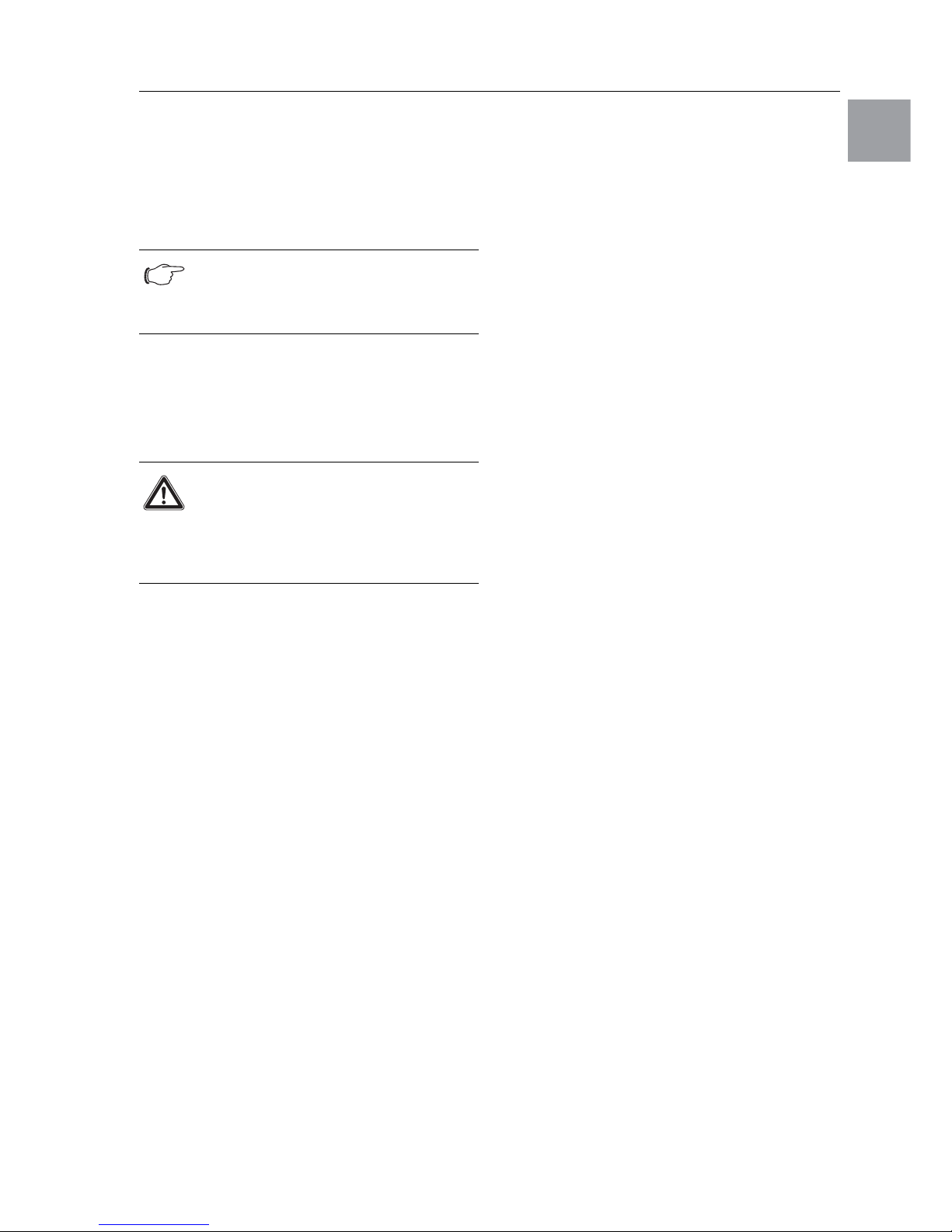
Fig. 20: Connection example: Door limit switch and master-slave operation
Legend
1 Master cooling unit
2 Slave cooling units
3 2-door enclosure with two door limit switches
4 Enclosure with door limit switch
4.6.3 Installing the power supply
• Complete the electrical installation by following
the wiring plan on the rear of the cooling unit
(see Fig. 1 on page 5, for key see page 21).
• If you would like the system messages from the
cooling unit to be evaluated via the system
message relay, you should also connect a suitable
low-voltage cable to connection clamps 3 – 5.
X2
CMC
I/O unit
RTT
Master
Adr.: 09
X1
X2
X3
X1
X2
X3
X1
X2
X3
X1
X2
X3
X2
X3
X2
X2
X2
X2
X2
X2
St. St. St.
Bu.
St.
Bu.
X2
Adr.: 11 Adr.: 12RTT
Slave
RTT
Slave
Adr.: 19RTT
Slave
St.
Bu.
St.
Bu.
3
2
1
X10
L1
L2
N
PE
1
2345
1
X10
X10 X10 X10 X10
X2 X2 X2 X2 X2 X2
X2
L1PE1
2345
L1
L2
N
PE
1
2345
L2 L3
L1PE1
2345
L2 L3
L1PE1
2345
L2 L3
L1PE1
2345
L2 L3
L1
L2
N
PE
1
23
4
5
X10
2
3
4
56
1
Adr.: 06 Adr.: 11 Adr.: 12 Adr.: 13 Adr.: 14 Adr.: 15
22 2 2 2
34432
Adr.: 16
4 Assembly and connection
RITTAL cooling unit assembly and operating instructions 15
EN
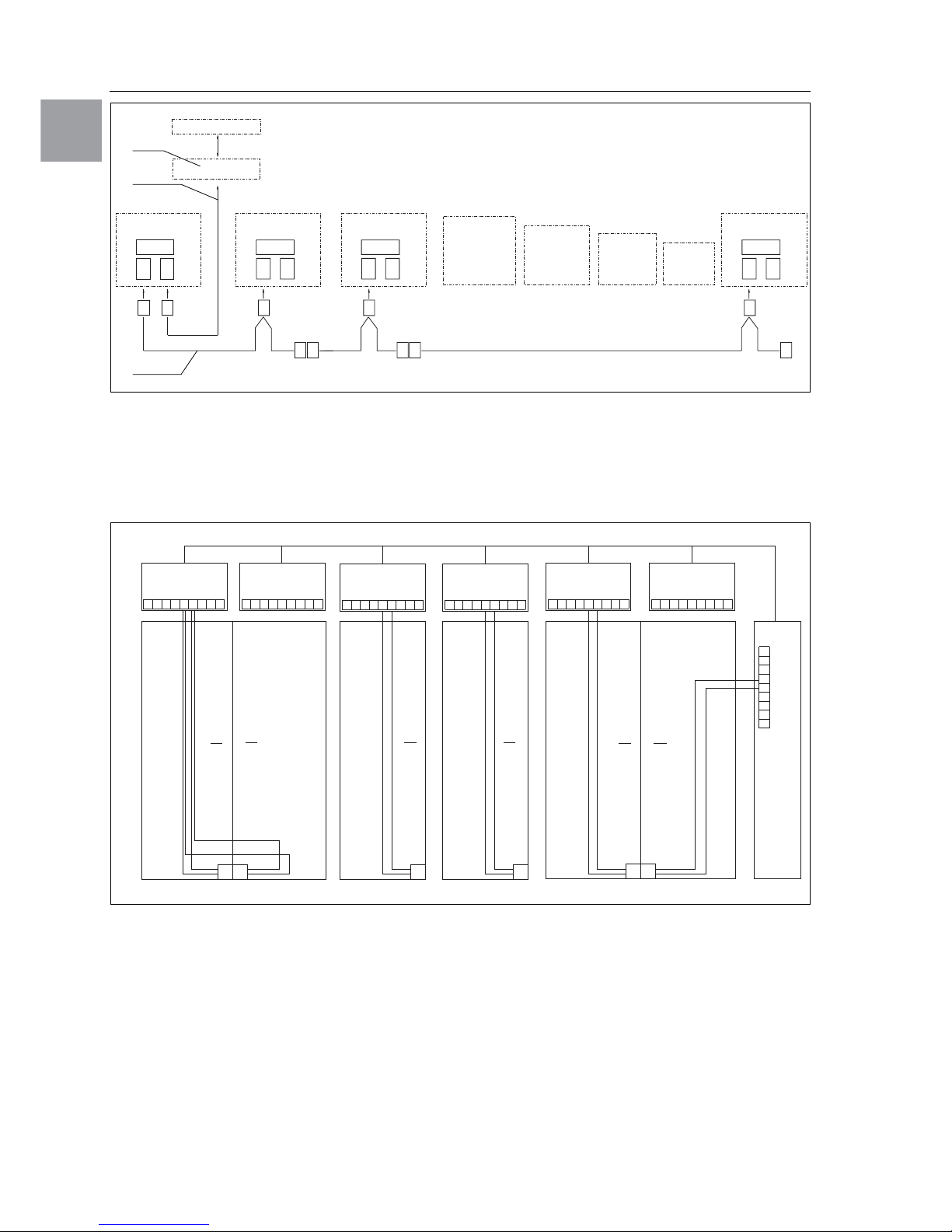
Fig. 21: Electrical wiring plan no. 1
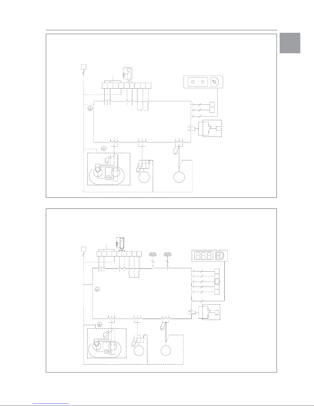
Fig. 22: Electrical wiring plan no. 2
22 21
A1
M1
M2
X1
L1
L2
N
PE
1
2345
S1
Mains
L
123 1 2 3 2 1
N
PE
5
Power
S1
Kx
M1
123
M2
123
M4
123
2
1
F2
NTC I red
NTC E blue
Ter m
A2
L1
L2
R1
2
2
8
B1
B2
P
F2
M4
M
1~
M
1~
C2
C1
R
S
F3
C
C4
SK 3302.100/.110, SK 3303.100/.110, SK 3302.200/.210, SK 3303.200/.210,
SK 3302.300/.310, SK 3361.100/.110, SK 3361.200/.210
M2
X1
L1
L2
N
PE
1
2345
L
123
12 321
N
PE
5
Power
M1
123
M2
123
M4
123
2
1
NTC I red
Serial
2
2
2
B1
B2
P
M4
M
1~
M
1~
C2
C1
R
S
F3
C
C4
S1
22
21
X2
X3
83
A2
NTC E blue
NTC C white
NTC A yellow
Level green
2
2
4
Ter m
F2
F2
B3
B4
B5
PE
S1
Kx
K2
K1
MS1
A1
PE
M1
SK 3303.500/.510, SK 3303.600/.610, SK 3361.500/.510, SK 3361.600/.610
Mains
16 RITTAL cooling unit assembly and operating instructions
4 Assembly and connection
EN
Fig. 23: Electrical wiring plan no. 3
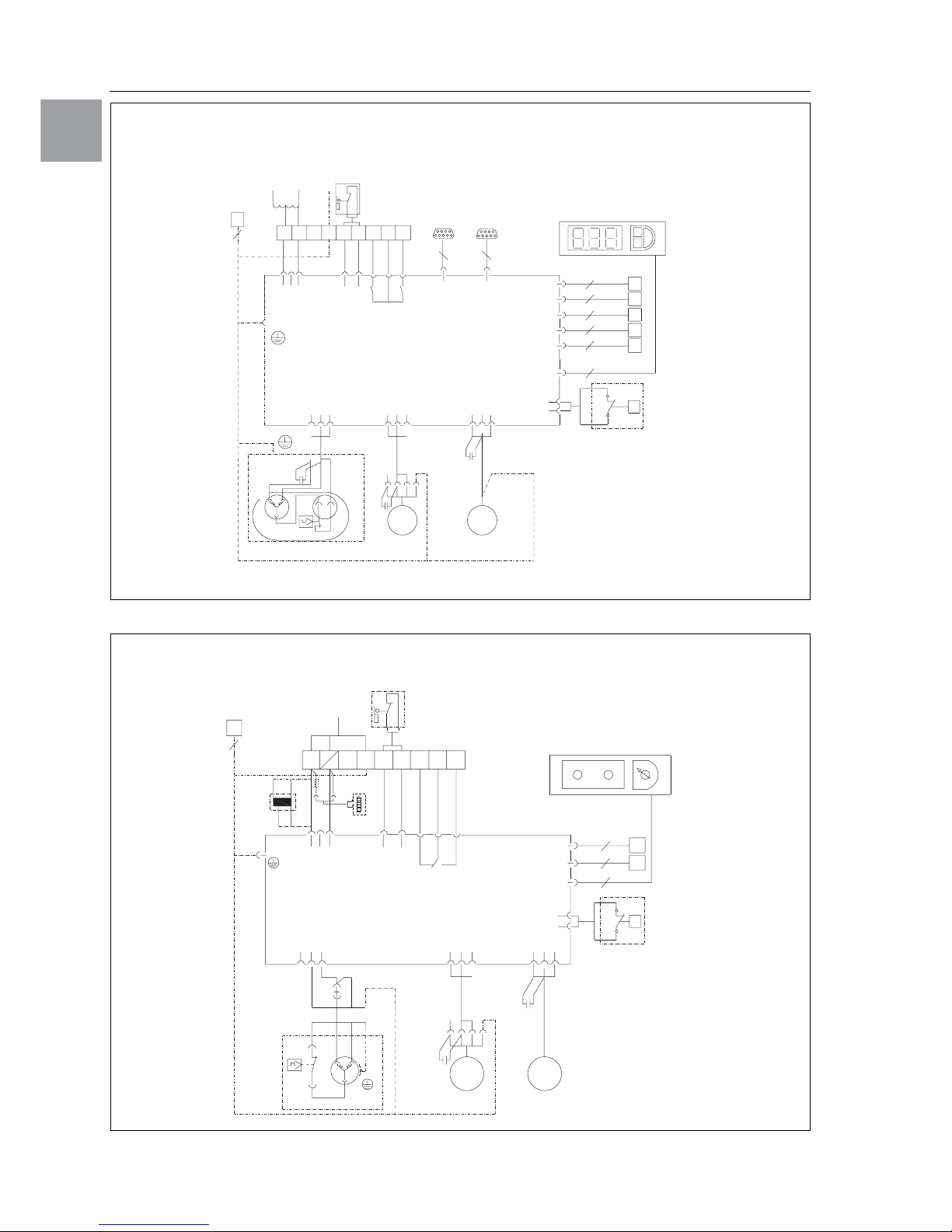
Fig. 24: Electrical wiring plan no. 4
SK 3361.540/.640
L1
PE
1
2
345
L2
N
S1
22
21
PE
5
X1
M1
1
2
3
1
2
3
LN
Power
S1
1
2
3
12
Kx
NTC I red
A2
1
F2
2
P
2
2
2
A1
M2
1
2
3
M4
1
2
3
S
R
C
M1
F3
C2
C4
M2
1~
M
M4
1~
M
C1
X2 X3
38
PE
K2
K1
MS1
Serial
NTC E blue
NTC C white
NTC A yellow
Level green
Term
2
2
4
F2
B1
B2
B3
B4
B5
PE
L1 L2 PE
T1
400 V
230 V
2345
M2
L1
L2
PE
1
S1
PE
5
L
123
N
Power
Kx
M1
123
M2
123
M4
13
NTC I red
NTC E blue
Ter m
L1 L2
R1
P
M4
M
1~
M
1~
X1
A2
2
2
8
B1
B2
F2
2
1
F2
C4
S1
12321
A1
PE
C2
L2L1
L
N
T1
2
22 21
N
C1
F3
S
R
1
3
M1
C
SK 3304.100/.200
F11
E1
Mains
 Loading...