

Rittal SK3237.100, SK3237.110, SK3237.124, SK3238.100, SK3238.110 Assemble And Operating Instructions
...
Montage-, Installations- und Bedienungsanleitung
Assembly and operating instructions
Notice d’emploi, d’installation et de montage
Montage- en bedieningshandleiding
Montage- och hanteringsanvisning
Istruzioni di montaggio e funzionamento
Instrucciones de montaje y funcionamiento
Filterlüfter
Fan-and-filter unit
Ventilateur à filtre
Ventilator
Filterfläkt
Ventilatore-filtro
Ventilador con filtro
SK 3237.xxx
SK 3238.xxx
SK 3239.xxx
SK 3240.xxx
SK 3241.xxx
SK 3243.xxx
SK 3244.xxx
SK 3245.xxx


Rittal fan-and-filter unit assembly and operating instructions 3
EN
Contents
1 Notes on documentation . . . . . . 4
1.1 Other applicable
documents . . . . . . . . . . . . . . . . 4
1.2 Storing the documents . . . . . . 4
1.3 Symbols used . . . . . . . . . . . . . 4
2 Safety notes . . . . . . . . . . . . . . . . 5
3 Device description. . . . . . . . . . . 5
3.1 Functional description . . . . . . 5
3.1.1 How it works . . . . . . . . . . . . . . . 5
3.1.2 Control. . . . . . . . . . . . . . . . . . . . 6
3.1.3 Safety equipment . . . . . . . . . . . 6
3.1.4 Filter mats . . . . . . . . . . . . . . . . . 6
3.2 Proper use . . . . . . . . . . . . . . . . 6
3.3 Scope of supply . . . . . . . . . . . 6
4 Assembly and connection . . . . 7
4.1 Choosing the installation
site . . . . . . . . . . . . . . . . . . . . . 7
4.2 Assembly instructions . . . . . . 7
4.2.1 General . . . . . . . . . . . . . . . . . . . 7
4.2.2 Layout of the components
in the enclosure. . . . . . . . . . . . . 7
4.3 Fitting the fan-and-filter unit
or outlet filter . . . . . . . . . . . . . . 7
4.3.1 Cutting out the enclosure . . . . . 7
4.3.2 Fitting the fan-and-filter unit . . . 7
4.4 Notes on electrical
installation . . . . . . . . . . . . . . . 8
4.4.1 Connection data . . . . . . . . . . . . 8
4.4.2 Overvoltage protection and
supply line load. . . . . . . . . . . . . 8
4.4.3 PE conductor connection . . . . . 8
5 Carrying out the electrical
installation . . . . . . . . . . . . . . . . . 9
5.1 Installing the power supply . . 9
5.2 Rotating the voltage
connection . . . . . . . . . . . . . . . 9
5.3 Changing the direction
of airflow . . . . . . . . . . . . . . . . . 9
6 Commissioning . . . . . . . . . . . . 10
6.1 Properties . . . . . . . . . . . . . . . 10
7 Changing the filter. . . . . . . . . . 10
7.1 Installing the filter media . . . 10
8
Inspection and maintenance
. . 11
8.1 General . . . . . . . . . . . . . . . . . 11
9 Storage and disposal . . . . . . . 11
10 Technical specifications. . . . . 12
11 Cut-out/drilling dimensions . . 16
12 EMC fan/outlet filter. . . . . . . . . 17
13 Connection diagrams . . . . . . . 18
14 EC declaration
of conformity . . . . . . . . . . . . . . 20
1 Notes on documentation
4 Rittal fan-and-filter unit assembly and operating instructions
EN
1 Notes on documentation
These assembly instructions are aimed at
tradespersons who are familiar with assembly and installation of the fan-and-filter
unit, and at trained specialists who are
familiar with operation of the fan-and-filter
unit.
1.1 Other applicable documents
There is one set of instructions for the unit
types described here:
– Assembly, installation and operating in-
structions enclosed with the unit as a
printed document and/or on CD-ROM.
We cannot accept any liability for damage
associated with failure to observe these
instructions. The instructions for the accessories used should also be observed
where applicable.
1.2 Storing the documents
These instructions and all associated documents are part of the product. They must
be given to the plant operator. The operator is responsible for storage of the documents so they are readily available when
needed.
1.3 Symbols used
Please observe the following safety instructions and other notes in this guide:
Symbol for an instructed action:
• The bullet point indicates that you
should perform an action.
Safety and other notes:
Danger!
Immediate danger to life
and limb!
Caution!
Potential threat to the product
and its environment.
Note:
Useful information
and special features.
2 Safety notes
Rittal fan-and-filter unit assembly and operating instructions 5
EN
2 Safety notes
Please observe the following general safety notes when assembling and operating
the unit:
– Assembly, installation and servicing may
only be performed by properly trained
specialists.
– Do not obstruct the air inlet and outlet of
the fan-and-filter unit inside and outside
the enclosure (see also section “4.2.2
Layout of the components in the enclosure”, page 7).
– The heat loss of the components in-
stalled in the enclosure must not exceed the specific air throughput of the
fan-and-filter unit.
– Fan-and-filter units must always be in-
stalled on vertical panels (door or walls).
– The louvres must always have their
opening pointing downwards.
– Use only original spare parts and acces-
sories.
– Do not make any changes to the fan-
and-filter unit other than those described in these and other applicable
instructions.
– The fan-and-filter unit must only be con-
nected to the mains with the system
de-energised. Connect the pre-fuse
specified on the rating plate.
– Changes to the direction of airflow must
only be carried out with the system deenergised.
– Changes to the positioning of the mains
connection must only be carried out with
the system de-energised.
– Never insert your fingers into the rotat-
ing fan wheel.
– Electrical connection and any repairs
may only be carried out by authorised
specialist personnel.
3 Device description
Depending on the model chosen, your fanand-filter unit may vary in appearance from
the illustrations contained in these instructions. However, the functions are identical
in principle.
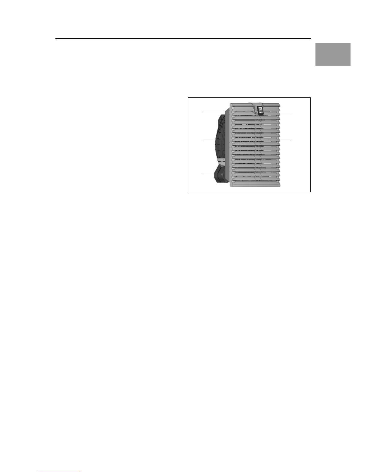
Fig. 1: Device description
Key
1 Function logo
(to release the louvred grille)
2 Louvred grille
3 Filter box with filter mat
4 Fan housing
5 Variable electrical connection
3.1 Functional description
The fan-and-filter unit in conjunction with
the corresponding outlet filter(s) is used to
dissipate heat loss from enclosures and
ventilate the enclosure, thereby protecting
temperature-sensitive components. This is
achieved via the direct infeed of ambient
air, the temperature of which must be less
than the admissible enclosure interior temperature. The system is fitted into prepared cut-outs in the door or walls of the
enclosure.
3.1.1 How it works
The fan-and-filter unit is comprised of the
following four main
components: Fan mo-
tor, filter box
, louvred grille with function
logo and filter medium.
1
2
3
4
5

3 Device description
6 Rittal fan-and-filter unit assembly and operating instructions
EN
3.1.2 Control
Rittal fan-and-filter units may be controlled
more efficiently
using a thermostat (Model
No. SK 3110.000), digital temperature
display (Model No. SK 3114.200), temperature-dependent speed control
(Model No. SK 3120.200) and/or hygrostat
(Model No. SK 3118.000).
Control unit (Model No. SK 3235.440) for
fan-and-filter unit SK 3245.xxx only.
3.1.3 Safety equipment
The fan is equipped with thermal winding
protection devices for protection against
excess current and even, in some cases,
against overtemperature. For rotary current fans, the winding protection is located
in the star earthing of the motor.
3.1.4 Filter mats
The fan-and-filter unit/outlet filter is supplied with a standard filter mat already
installed. Depending on the incidence of
dust, you will need to replace the filter mat
from time to time.
In order to increase the protection category, and in the case of dust with a grain size
of < 10 µm, we recommend the use of fine
filter mats.
3.2 Proper use
Rittal fan-and-filter units were developed
and designed in accordance with the
state of the art and the recognised rules
governing technical safety. Nevertheless,
if used improperly, they may pose a threat
to life and limb or cause damage to property. The unit is only intended for ventilating enclosures and electronic cases. Any
other use is deemed improper. The manufacturer will not be liable for any damages
caused as a result of improper use, or for
incorrect assembly, installation or use.
All risk is borne solely by the user.
Proper usage also includes the observation of all valid documents and compliance with the inspection and servicing
conditions.
3.3 Scope of supply
The fan is supplied in a packaging unit in
a fully assembled state and ready to connect.
Please check the scope of supply for completeness.
Tab. 1: Scope of supply
Note:
The air throughput volume
will be reduced.
Special filter mats are required
for EMC fan-and-filter units
(see accessories).
Qty. Description
1 Fan-and-filter unit
4
1
– Mounting screws
(not for SK 3237.1xx
to SK 3239.1xx)
– Assembly, installation and
operating instructions
1 Drilling template, self-adhesive
4 Assembly and connection
Rittal fan-and-filter unit assembly and operating instructions 7
EN
4 Assembly and connection
4.1 Choosing the installation site
When choosing the installation site for the
enclosure, please observe the following:
– The site for the enclosure, and hence
the arrangement of the fan-and-filter
unit, must be carefully selected so as to
ensure good ventilation.
– The site must be free from excessive dirt
and moisture.
– The ambient temperature must be lower
than the permissible enclosure interior
temperature.
– The mains connection data as stated
on the rating plate of the unit must be
guaranteed.
4.2 Assembly instructions
4.2.1 General
– Check that the packaging does not show
any signs of damage. Packaging damage may be the cause of a subsequent
functional failure.
– The fan-and-filter unit and outlet filter
must always be mounted on an enclosure in order to ensure air exchange.
– The enclosure must be sealed on all
sides (IP 54). If the enclosure has a leak,
unfiltered, contaminated air may enter
the enclosure, depending on the direction of airflow of the fan.
4.2.2 Layout of the components
in the enclosure
Exercise particular caution with the airflow
from the blowers of built-in components.
For installation, it is important to ensure
that the airflows of fans and built-in components do not have a negative influence
on one another (air short-circuit).
The corresponding minimum distances
between the fan and component must be
observed in order to ensure unhindered air
circulation.
4.3 Fitting the fan-and-filter unit
or outlet filter
The fan-and-filter unit or outlet filter is
mounted on a vertical panel of the enclosure:
• For this purpose, the appropriate door,
side or rear panel must be cut out using
the supplied drilling template.
The fan-and-filter unit is generally fitted in
the lower part of the enclosure, and the
outlet filter in the upper part.
4.3.1 Cutting out the enclosure
• Stick the supplied self-adhesive drilling
template to the envisaged position on
the door, side or rear panel of the enclo-
sure.
There are dimensioning lines on the drilling plate for the cut-out and for the holes
required for mounting and securing the
fan, depending on the metal thickness
(cf. also Fig. 8 and Fig. 9, page 16).
• Make the cut-outs including the line
width as per the drilling template.
Deburr the cut-outs.
4.3.2 Fitting the fan-and-filter unit
• The fan may be fitted without tools, by
simply snapping into the preconfigured
mounting cut-out.
• However, if the metal thickness is great-
er than 3 mm, the fan will need to be
screw-fastened. To this end, remove the
louvred grille in order to gain access to
the lower mounting holes.
Note:
The outlet filter should be
at least the same size as the
fan-and-filter unit.
Risk of injury!
Carefully deburr all cut-outs
to prevent injuries caused by
sharp edges.
 Loading...