

Page 1
Montage-, Installations- und Bedienungsanleitung
Assembly and operating instructions
Manuel d’installation et de maintenance
R
RITTAL
TOP
THERM
Rittal
Thermoelectric Cooler
SK 3201.200
SK 3201.300
Montage- en bedieningshandleiding
Montage- och hanteringsanvisning
Istruzioni di montaggio e funzionamento
Instrucciones de montaje
SchaltschrankKühlgerät
Cooling unit
Climatiseur
Koelaggregaat
Kylaggregat
Condizionatore
per armadi
Refrigerador
para armarios
Page 2

2 Rittal Thermoelectric Cooler assembly and operating instructions
GB
Before installation of the cooling unit,
please read this manual completely and carefully.
The manual is a permanent part of the supplied system
and must be retained until the device is decommissioned.
We thank you for deciding to purchase a Rittal product!
The Rittal Thermoelectric Cooler is a high-performance thermoelectric light-weight cooling unit with
the highest efficiency (COP > 1) of its class!
The cooling unit is particularly suitable for the climate
control of operating housings and small enclosures!
Before using the cooling unit, read this manual carefully in order to make full use of the excellent performance characteristics of the product.
Rittal GmbH & Co. KG products are continually
adapted to the requirements and needs of our customers. This means the information concerning the
product characteristics and functions contained in
this manual can be changed without notice in the
case of product improvements.
Page 3

Rittal Thermoelectric Cooler assembly and operating instructions 3
GB
Contents
1 Unpacking and checking. . . . . . . . . . 4
2 Notes on documentation. . . . . . . . . . 4
2.1 Retention of the manual . . . . . . . . . . . . . . . . 4
3 Safety notes . . . . . . . . . . . . . . . . . . . . 5
3.1 Proper usage . . . . . . . . . . . . . . . . . . . . . . . . . 5
3.2 Standards, guidelines. . . . . . . . . . . . . . . . . . 5
4 How it works. . . . . . . . . . . . . . . . . . . . 6
5 Control . . . . . . . . . . . . . . . . . . . . . . . . 7
6 Device description . . . . . . . . . . . . . . . 8
7 Device mounting . . . . . . . . . . . . . . . . 9
7.1 External mounting. . . . . . . . . . . . . . . . . . . . 10
7.2 Internal mounting . . . . . . . . . . . . . . . . . . . . 10
8 Filter mounting. . . . . . . . . . . . . . . . . 11
9 Mounting of the
condensate discharge . . . . . . . . . . . 11
10 Electrical connection. . . . . . . . . . . . 12
10.1 Connection data . . . . . . . . . . . . . . . . . . . . . 12
11 Interfaces . . . . . . . . . . . . . . . . . . . . . 13
11.1 Interface X1 –
power supply and alarm output. . . . . . . . . 13
11.2 Interface X2 –
device programming. . . . . . . . . . . . . . . . . . 13
11.3 Interface X3 –
integration in a higher-level
monitoring system . . . . . . . . . . . . . . . . . . . 13
12 Earth connection . . . . . . . . . . . . . . . 13
13 Commissioning . . . . . . . . . . . . . . . . 14
14 Status and function displays . . . . . 14
15 Technical specifications . . . . . . . . . 15
16 Maintenance and cleaning . . . . . . . 16
16.1 Maintenance . . . . . . . . . . . . . . . . . . . . . . . . 16
16.2 Cleaning . . . . . . . . . . . . . . . . . . . . . . . . . . . 16
17 Fault correction . . . . . . . . . . . . . . . . 17
18 Disposal . . . . . . . . . . . . . . . . . . . . . . 18
19 Guarantee . . . . . . . . . . . . . . . . . . . . . 18
Page 4
4 Rittal Thermoelectric Cooler assembly and operating instructions
1 Unpacking and checking
GB
1 Unpacking and checking
The Rittal Thermoelectric Cooler is delivered in transport packaging.
The supplied system consists of:
1 x cooling unit
1 x assembly and operating instructions
1 x accessories bag
Shipping bag content:
1 x assembly and operating instructions
1 x self-adhesive sealing tape
1 x filter mat
1 x drilling template
1 x connector plug (power supply and alarm output)
Assembly parts
Check that the delivered system is complete and undamaged. Any obvious transport damage must be
reported without delay to the responsible transport
company.
The latest version of the “General conditions for
deliveries and services” of the ZVEI (Central Association of the German Electrotechnical Industry)
applies.
Prior to disposal, check the packaging material for
any loose function parts!
2 Notes on documentation
Assembly and operating instructions are available in
printed form (provided with the supplied system) and
as a PDF file for the
Rittal Thermoelectric Cooler.
A PDF file is available as free download from
www.rittal.com. ACROBAT READER® is required
to view the file.
The accompanying documentation must be observed for the assembly, installation and operation of
the cooling unit. Rittal cannot accept any liability for
damage associated with the failure to observe these
instructions.
The information and safety notes in this manual
follow the following structure:
Safety and other instructions:
2.1 Retention of the manual
The operating company is responsible for retaining
the manual.
No part of the manual may be reproduced or
processed, copied or distributed using electronic
systems in any form (printed, microfilm or any
other form) without the written approval of Rittal
GmbH & Co. KG. No liability can be assumed for
any damage resulting from the non-observance
of the information contained in this manual.
Danger!
Warning of a potential danger source.
Danger to life and health in case of
non-observance!
Danger!
Warning of a dangerous electrical
voltage.
Danger to life and health in case of
non-observance!
Danger!
Warning of slippery surface.
Danger to life and health in case of
non-observance!
Note:
Useful information and special features.
Page 5

3 Safety notes
Rittal Thermoelectric Cooler assembly and operating instructions 5
GB
3 Safety notes
The following general safety notes must be observed
for the assembly, installation and operation of the
cooling unit:
– The assembly, installation and servicing of the
cooling unit may only be performed by properly
trained specialists.
– The mains connector of the cooling unit must only
be connected and disconnected with the system
de-energised. The device must be protected with
a pre-fuse.
– No changes may be made to the cooling unit.
– Only the customer service or authorised personnel
may open the device. The opening of the device by
the user or unauthorised persons is not permitted
and will void any warranty claim.
– The cooling unit is intended only for the climate
control of enclosures and housings. Any other use
shall be deemed improper. The manufacturer is
not liable for any resulting damage! Proper usage
also includes the observance of all valid docu-
ments and compliance with the inspection and
servicing conditions.
– The air inlet and outlet openings on the cooling unit
must not be covered.
– Use only original spare parts and accessories
expressly approved for the Rittal Thermoelectric
Cooler. Otherwise malfunctions or damage can
occur. Warranty claims cannot be accepted for
such damage.
3.1 Proper usage
The Rittal Thermoelectric Cooler conforms to the
current state-of-the-art.
The cooling unit is intended only for cooling enclosures and operating housings. Any other use shall
be deemed improper.
Proper usage is possible only when all associated
documents, and the device-specific assembly and
operating instructions are observed.
The manufacturer is not liable for any damage resulting from improper use.
3.2 Standards, guidelines
The Rittal Thermoelectric Cooler meets the requirements of the following guidelines and standards:
– DIN 3168 Section 4.5 (enclosure cooling units)
– Machine directive 98/37/EC
– Low-voltage directive 2006/95/EC
– Electromagnetic compatibility 2004/108/EC
– EN 378-1 to -4 (cooling systems and heat pumps)
– EN ISO 12100-1 and -2 (machine safety)
– EN 294 (safety distances for contact)
– EN 60 204-1 (machine electrical equipment)
– EN 60 529 (degrees of protection provided by the
housing IP rating)
– EN 60 335-1 and -2-40
(safety of electrical devices)
– EN 55 011 Kl B (radio disturbances)
– EN 61 000-3-11 (electromagnetic compatibility)
– ISO 9001/14001
– RoHs COMPLIANT 2002/95/EC
Page 6
6 Rittal Thermoelectric Cooler assembly and operating instructions
4 How it works
GB
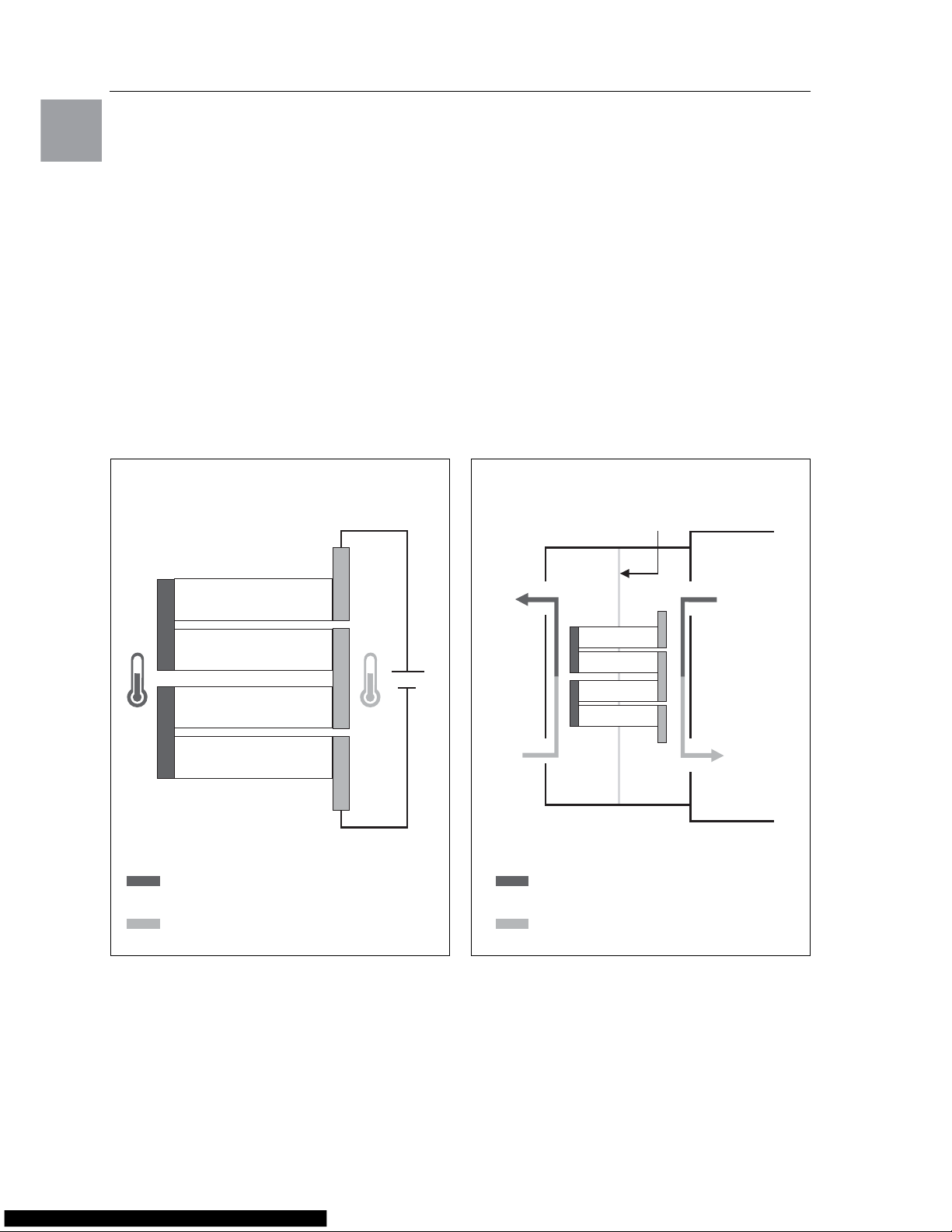
4 How it works
The Rittal Thermoelectric Cooler uses the Peltier effect for cooling. This effect is based on the principle
that an electric direct-current flowing through a circuit consisting of two different metals causes the
cooling of one contact point and the heating of the
other contact points. An appropriate layout for the
cooling production is designated as Peltier element.
When the Peltier effect is used for enclosure climate
control, an air flow is fed over the upper and lower
connection point. The heat energy is released or
accepted from the air flow to the Peltier element.
The air flow that releases the heat energy to the element is introduced as cooling air flow in the enclosure or the operating housing. After
the heating of the
cooling air flow by the active installed equipemt
, it is
returned to the cooling unit and fed for renewed cooling over the “cold” side of the Peltier element. This
produces an air circulation that causes the cooling of
the enclosure or the operating housing.
The air flow that accepts the heat energy from the
“warm” side of the Peltier element is released as
warm air flow to the external air circuit of the cooling
unit. This means the heat produced by the components in the enclosure is dissipated to the ambient air
surrounding the cooling unit.
Fig. 1: Peltier element Fig. 2: Peltier cooling unit
n-doped
n-doped
p-doped
p-doped
Warm area
Cold area
+
–
Divider panel
Environment
Enclosure/operating housing
Warm area
Cold area
Page 7

5 Control
Rittal Thermoelectric Cooler assembly and operating instructions 7
GB
5 Control
The Rittal Thermoelectric Cooler controls the cooling
capacity of the Peltier elements and the air throughput of the integrated fans so that the required internal
temperature of the enclosure or the operating housing is set with high accuracy. For this purpose, the
device permanently monitors the air entry temperature at the warm air entry (internal circulation). If this
temperature exceeds a parameterised temperature
value (factory setting: 35°C), the device starts cooling operation. To do this, the trigger voltages of the
Peltier elements and fans are corrected by a PID
control so that the cooling capacity required for the
cooling is always available and the cooling operation
is provided with the least possible power. The redundant fans in the external air circuit of the Rittal Thermoelectric Cooler have variable air delivery rates
(and consequently variable speeds) appropriate for
the required cooling capacity. If only limited or indeed no cooling capacity is required, this control behaviour can lead to a temporary inactivity of the fans
in the external air circuit. This does not constitute
a malfunction of the device, but rather an extreme
power-saving operating state that also increases the
service life of the used fans.
Note:
The fan speed in the external air circuit of
the cooling unit is matched to the current
cooling capacity requirement.
Consequently, a stoppage of the fans –
interrupted by periodic, short-term fan
starts – is not a malfunction of the device,
but rather represents an extreme powersaving operating state!
Fig. 3: Control behaviour of the fans in the external air circuit
max.
Cooling capacity requirement
Fan speed in the external air circuit
Fan off
min.
Page 8

8 Rittal Thermoelectric Cooler assembly and operating instructions
6 Device description
GB
6 Device description
Fig. 4: Device front Fig. 5: Device rear
1 2 3
4
5
7
6
1098
11
12
13
14
16
15
Legend
1 Status display
2 Function display
3 Housing
4 Louvred grille
5 Warm air outlet opening – external air circuit
6 Cold air inlet opening with filter element
(optional) – external air circuit
7 Condensate discharge
8 Interface X1: supply voltage and alarm output
9 Interface X2: USB 2.0, type B
10 Interface X3: RJ 45
11 Connection diagram
12 Warm air inlet opening – air internal circuit
13 Earth connection
14 Cold air outlet opening – air internal circuit
15 Blind nut
16 Rating plate (on the device lower side)
Page 9

7 Device mounting
Rittal Thermoelectric Cooler assembly and operating instructions 9
GB
7 Device mounting
The following principles must be observed for determining the mounting position on the enclosure or operating housing:
The Rittal Thermoelectric Cooler is mounted as external or full internal mounting.
The supplied drilling template must be used to fasten
the cooling unit on the enclosure or the operating
housing.
The drilling template provides dimension lines for the
various installation options of the cooling unit.
Identify appropriate lines and dimensions on the
drilling template for the required mounting type
(external or full internal mounting) using figures 6
and 7.
Drill the required holes for fastening the cooling unit
and then cut the required cut-out, including the line
width, in accordance with the drilling template.
The direct incidence of cold air on temperature-sensitive components must be
avoided!
Components with integrated fans
determine the cooling air routing in the
enclosure or operating housing.
The mounting position of the cooling unit
must be chosen so that the cooling air flow
supports the heat dissipation of these components.
A free space of at least 100 mm is required
in front of the air inlet and outlet openings of
the cooling unit in the internal and external
circuit.
The cooling unit must be positioned on
the enclosure so that the condensate discharge opening is located at the lowest
point of the cooling unit.
Risk of injury!
Wear protective gear (safety glasses,
protective gloves) when cutting the
mounting cut-out and drilling the
fastening holes.
Carefully deburr all drilled holes and
cut-outs to prevent injuries caused by
sharp edges.
Fig. 6: Mounting cut-out and hole sizes
for external mounting
Fig. 7: Mounting cut-out and hole sizes
for internal mounting (full internal mounting)
377
366
400
25
25
11.5
15
Ø 6.5
10012.5
8.5
108
125
Climate control unit external contour
386
400
25
15
100
15
25
40
377
25
18
Ø 6.5 Ø 12
10
7
11.5
85
11
12.5
8.5
108
125
12
Climate control unit external contour
Page 10

10 Rittal Thermoelectric Cooler assembly and operating instructions
7 Device mounting
GB
7.1 External mounting
When the cooling unit is mounted as externallymounted variant, the supplied self-adhesive sealing
tape must be fastened on the device rear wall of the
cooling unit so that no gaps result at the joint edges.
Then screw the supplied studs into the blind nuts at
the rear of the unit. Secure the cooling unit using the
supplied washers and nuts.
Fig. 8: Position of the sealing tape
Fig. 9: Fastening the cooling unit
Fig. 10: External and internal mounting
Fig. 11: Permissible mounting positions
7.2 Internal mounting
For the full internal mounting of the cooling unit, the
louvred grille must be carefully removed from the device. The self-adhesive sealing tape supplied must
be placed on the front of the cooling unit (the device
face from which the louvred grille has been removed) so that no gaps result at the joints. Then
screw the supplied studs into the blind nuts at the
front of the unit. Secure the cooling unit using the
supplied washers and nuts. To complete the mounting, the louvred grille must be re-attached.
Fig. 12: Position of the sealing tape
Fig. 13: Fastening the cooling unit
125
400
400
155
55100
10055
Internal mountingExternal mounting
External
mounting,
vertical
External
mounting,
horizontal
Internal
mounting,
horizontal
Internal
mounting,
vertical
max. 45°
max. 45°
max. 45°
max. 45°
Page 11

8 Filter mounting
Rittal Thermoelectric Cooler assembly and operating instructions 11
GB
8 Filter mounting
The Rittal Thermoelectric Cooler can be equipped
with a device filter (supplied).
An appropriate filter unit is recommended when the
cooling unit is used in ambient air subject to dust.
When a filter is installed, the lower louvred grille in
the air inlet of the cooling unit must be removed. To
do this, raise the louvred grille with a light tug at the
marked position (see Figure 14) and withdraw it at
the front. Then place the filter mat in the filter holder
of the device. The colour-marked side of the filter mat
must face the device. Then re-mount the louvred
grille and snap it into position by applying light pressure.
Fig. 14: Removable louvred grille
9 Mounting the
condensate discharge
The Rittal Thermoelectric Cooler is equipped with
a condensate discharge.
Fig. 15: Condensate discharge
The controlled condensate discharge requires a
condensate discharge hose be connected to the
cooling unit’s condensate discharge supports.
The condensate hose is available as accessory.
The installation of the condensate hose requires
that it
– is laid with a gradient (no siphon formation),
– does not have any kinks,
– must not have a reduced cross-section if extended.
Note:
When a filter unit is used, it must be cleaned
regularly or, if necessary, replaced.
Risk of injury!
The operation of the cooling unit without
controlled condensate discharge can
cause liquid to accumulate below the
device.
Condensate
discharge
Page 12

12 Rittal Thermoelectric Cooler assembly and operating instructions
10 Electrical connection
GB
10 Electrical connection
10.1 Connection data
– The mains voltage and frequency must corres-
pond to the values stated on the rating plate.
– An all-range fuse specified on the rating plate must
be connected upstream as line and device protection.
– No additional temperature control is allowed to be
connected upstream of the cooling unit on the
supply side.
– An isolating device that ensures a contact opening
of at least 3 mm in switched-off state must be
connected upstream of the cooling unit.
– The mains connection must ensure low-noise
potential equalisation.
Fig. 16: Rating plate
The Rittal Thermoelectric Cooler is available as
version with integrated multi-range power pack
(100 – 240 V) and as 24 V variant (without integrated
power pack).
Fig. 17: SK 3201.200 connection diagram,
with integrated power pack
Fig. 18: SK 3201.300 connection diagram,
without integrated power pack
Legend
A1 Power PCB
A2 Power pack
B1 Temperature sensor, internal temperature
B2 Ambient temperature sensor
B3 Temperature sensor, power pack
H1/H2 Status and function display
M2.1 Condenser fan 1
M2.2 Condenser fan 2
M4 Evaporator fan
TE Thermoelectric elements
X1 Terminal strip
X2 USB connection
X3 Optional interface
Danger!
Warning of a dangerous electrical
voltage.
Danger to life and health in case of
non-observance!
M M M
M4
MS1
3
2
1
213
Ser ial
A1
TE
1
2
Power
PE
+
–
M2.2
1
3
2
M4
3
2
1
X1
1PE2
3
M2.2
4
M2.1
1
3
2
M2.1
4 4
L1
N
PE
TE
~
–
A2
PE
Mains
X2
X3
Alarm
NTC_O YELLOW
NTC_I RED
2
B2
2
B1
2
B3
NTC_N WHITE
H1 H2
M4
NTC_O YELLOW
NTC_I RED
MS1
3
2
1
2
1
3
Ser ial
A1
TE
1
2
Power
PE
+
–
M2.2
1
3
2
M4
3
2
1
PE
X1
Mains
1PE23
X2
X3
2
B2
2
B1
M2.2
4
M2.1
1
3
2
M2.1
M
4
M M
4
+ –
PE
TE
Alarm
H1 H2
Page 13

11 Interfaces
Rittal Thermoelectric Cooler assembly and operating instructions 13
GB
11 Interfaces
Fig. 19: Designations of the device interfaces
11.1 Interface X1 –
power supply and alarm output
– Power supply
SK 3201.200: AC: 100 – 240 V, 50/60 Hz
SK 3201.300: DC: 24 V (SELV)
– Change-over contact/alarm output (floating
connection)
Switching load: AC: 250 V/2 A, DC: 6...30 V/2 A
The signal relay releases for overtemperature,
sensor break and fan failures.
Fig. 20: Change-over contact assignment
11.2 Interface X2 –
device programming
– USB 2.0
11.3 Interface X3 –
integration in a higher-level
monitoring system
– RJ 45
The interface X3 permits the connection of the cooling unit in higher-level monitoring systems.
12 Earth connection
The Rittal Thermoelectric Cooler is equipped with a
potential equalisation connection point. A conductor
with a nominal cross-section of at least 6 mm2 must
be connected to this connection point and included
in the provided potential equalisation.
Fig. 21: Contact point for potential equalisation
X2X1 X3
PE
1+
–
23
24 V DC
0322231
X2X1 X3
PEL1
L2
N
123
0322416
Connection terminal designation SK 3201.300
Connection terminal designation SK 3201.200
Interface X3Interface X2Interface X1
Interface X3Interface X2Interface X1
Pin 1 Pin 2 Pin 3
Note:
The electrical signals at the interface X3
are extra-low voltages (not extra-low safety
voltages in accordance with EN 60 335).
Note:
According to the standard, the PE conductor in the mains connection cable is not
classified as an equipotential bonding conductor.
X2X1 X3
PE
123
24 V DC
0322231
Contact point for
the potential equalisation
Page 14

14 Rittal Thermoelectric Cooler assembly and operating instructions
13 Commissioning
GB
13 Commissioning
The Rittal Thermoelectric Cooler is operational immediately after connection of the power supply. If the
factory setting is unchanged, the temperature control of the enclosure or operating housing uses the
following parameters:
Set enclosure interior temperature: +35°C
Start temperature for cooling operation: +35°C
Overtemperature alarm message: +45°C
Under normal operating conditions, device operation with unchanged factory setting should ensure a
problem-free enclosure climate control. If it would
appear to be useful to change the predefined parameters for special climate control requirements,
this can be realised with programming software. In
this case, please contact the device manufacturer.
14 Status and function displays
The Rittal Thermoelectric Cooler is equipped with
a status and function display. Two coloured LEDs
show the status, alarm and error messages that indicate the operating state of the cooling unit.
Fig. 22: Status and function displays on the cooling unit
Tab. 1: Function display
Tab. 2: Status display
Function LED
Description
Off Unit OFF or Cooling OFF
Green Cooling operation ON
Red Error – unit
Status LED
Description
Off Unit OFF
Green Unit OK
Orange Warning (temperature alarm,
temperature > alarm value)
Red Error (sensor defective, fan
defective, thermoelectric module
defective)
Function
display
Status
display
Page 15

15 Technical specifications
Rittal Thermoelectric Cooler assembly and operating instructions 15
GB
15 Technical specifications
Tab. 3: Technical specifications
Tab. 4: Setting ranges
Fig. 23:
Cooling output characteristic curve for full internal mounting and an enclosure internal temperature T
i
of 35°C
Model No. SK
3201.200 3201.300
Dimensions in mm
W
H
D
125
400
155
Operating voltage in volts, Hz 100 – 240 V AC, 50/60 Hz 24 V DC
Useful cooling output
Q
k
in accordance with DIN 3168
L 35
L 35
100 W
Power consumption P
el
in accordance with DIN 3168
L 35
L 35
Max. 100 W
Refrigeration factor (max.)/COP
L 35
L 35
1.0 1.2
Power pack Integral –
Housing colour RAL 7024/anodised aluminium
Protection category
according to EN 60 529
Internal circuit
External circuit
IP 54
IP 34
Weight 3.0 kg 2.4 kg
Noise level Max. 63 dB(A)
Operating temperature +5°C to +55°C
Storage temperature –20°C to +70°C
Installation position Horizontal or vertical
Air throughput, unimpeded air flow
Internal circuit
External circuit
132 m
3
/h
132 m
3
/h
Temperature setting range +20°C to +55°C
Cooling activation temperature +35°C (factory setting)
Type of connection Plug-in terminal strip
Pre-fuse gG 2 A 10 A
Floating change-over contact;
contact loading
DC: 6...30 V / 0.1...2 A
AC: 250 V / 2 A
Technical modifications reserved.
.
Variable Range Default value EEPROM
Temperature conversion °C/°F 0...1 0 (°C) Yes
Cooling setpoint +20 to +55°C 35°C Yes
Overtemperature alarm message (0)2...15 K (0 = off) 10 K Yes
Internal fan deactivation (during cooling pauses) 0...1 0 (no deactivation) Yes
2520 30 35 40 45
0
140
160
120
100
80
60
40
20
Cooling output in W
T
i
Ambient temperature in °C
Ti = Enclosure internal temperature (°C)
Room temperature
Page 16

16 Rittal Thermoelectric Cooler assembly and operating instructions
16 Maintenance and cleaning
GB
16 Maintenance and cleaning
16.1 Maintenance
The Rittal Thermoelectric Cooler is low-maintenance.
16.2 Cleaning
If the Rittal Thermoelectric Cooler is used in ambient
air subject to dust, dust can accumulate in the area
of the air inlet and outlet openings and on the heat
transferring surfaces of the Peltier element. This can
cause a reduction of the air flow in the device and
thus a gradually reducing cooling capacity. To remove the dust, withdraw the louvred grille at the device front side. Blow compressed air through the air
inlet and outlet openings of the cooling unit.
If the Peltier cooling unit is equipped with a device
filter, it must be cleaned or replaced regularly. The
filter mat can be cleaned by washing, dusting or
blowing with compressed air. The high-quality filter
material used for the mat means the cleaning does
not impair the filter-technical properties and the form
stability. The fire class remains unchanged!
Danger!
Prior to any cleaning or maintenance
work, the power to the cooling unit must
be disconnected!
Note:
When the filter is replaced, use only filter
materials approved for the Rittal Thermoelectric Cooler.
The dust collecting efficiency and dust
storage capacity of the filter equipment
chosen is matched to the rated flow speed
of the cooling unit in the external air circuit
and so guarantees an excellent dust
filtering for a high useful cooling output.
Page 17

17 Fault correction
Rittal Thermoelectric Cooler assembly and operating instructions 17
GB
17 Fault correction
Tab. 5: Fault correction
Fault description Possible cause Correction
The unit does not switch on. No power supply. Check the mains connection and the
pre-fuse.
The unit does not cool adequately. The air circulation in the enclosure is
impaired.
Check the air circulation inside the
enclosure. Check, in particular, those
components equipped with a fan.
Check the free spaces above and
below the main heat dissipation
sources.
Ambient temperature too high. Reduce the ambient temperature.
Protect the unit from radiation heat
caused by direct sunshine and hot
surfaces.
Filter equipment contaminated. Check the filter and, if necessary,
clean or replace.
Internal fan defective.
Replace (Rittal Service).
External fan defective. Replace (Rittal Service).
The heat produced in the enclosure
exceeds the cooling capacity of the
Peltier cooling unit.
Reduce the heat loss.
Condensation. Enclosure leakages. Check the enclosure for leaks (IP 54).
Check, in particular, the cable entry
points for leaks.
Internal temperature of enclosure set
too low.
Check the set enclosure internal
temperature (factory setting: +35°C).
Page 18

18 Rittal Thermoelectric Cooler assembly and operating instructions
18 Disposal
GB
18 Disposal
To ensure the material reuse of the recyclable packaging materials, they must be delivered to the local
collection sites.
The cooling unit must be delivered to a waste management service provider that ensures the correct
reuse of the recyclable parts and the proper disposal
of the rest.
19 Guarantee
Provided the unit is used correctly (refer to the
operating instructions), Rittal gives its customers
a 24-month “Rittal manufacturer’s guarantee”
starting with date of manufacture.
If, within the guarantee period, during the 24 months
after manufacture, a malfunction occurs on the product that substantially adversely affects its functionality, Rittal will, within a reasonable period of time, rectify the malfunction by telephone service or, if necessary, by replacement, repair or other measures, at its
option. If this is inappropriate for the customer, Rittal
also has the possibility to provide the customer with
the replacement parts required to correct the malfunction.
Within the scope of its guarantee, Rittal will bear all
costs concerning the dispatching, deployment and
accommodation of its staff and with replacing or repairing any parts, provided the malfunction occurred
during the proper usage of the products and provided the costs are not increased by the movement of
the products to a place other than that where they
were originally delivered. In addition, Rittal will bear
the necessary costs for procuring and delivering the
replacement parts to the place where the products
were originally delivered.
Any parts delivered for or in replacement will be new
or in mint condition and in a fully functional state free
of faults; the replaced parts will become Rittal’s
property; the customer warrants that no rights of any
third parties will obstruct that exchange and transfer
of title.
Any claims based on this guarantee are to be submitted to Rittal in writing within one month after the
occurrence of the malfunction.
Any further claims, in particular claims for damages
,
are not covered by the guarantee. The statutory liability for defects is not affected by the guarantee.
Page 19

Switch to perfection
R
Power Distribution
Stromverteilung
Distribution de courant
Stroomverdeling
Strömfördelning
Distribuzione di corrente
Distribución de corriente
IT Solutions
IT-Solutions
Solutions IT
IT-Solutions
IT-lösningar
Soluzioni per IT
Soluciones TI
System-Klimatisierung
System Climate Control
Climatisation
Systeemklimatisering
Systemklimatisering
Soluzioni di climatizzazione
Climatización de sistemas
Schaltschrank-Systeme
Industrial Enclosures
Coffrets et armoires électriques
Kastsystemen
Apparatskåpssystem
Armadi per quadri di comando
Sistemas de armarios
Elektronik-Aufbau-Systeme
Electronic Packaging
Electronique
Electronic Packaging Systems
Electronic Packaging
Contenitori per elettronica
Sistemas de montaje para la electrónica
Communication Systems
Communication Systems
Armoires outdoor
Outdoor-behuizingen
Communication Systems
Soluzioni outdoor
Sistemas de comunicación
Rittal GmbH & Co. KG · Postfach 1662 · D-35726 Herborn
Tel.: +49 (0) 2772 505-0 · Fax: +49 (0) 2772 505-2319 · eMail: info@rittal.de · www.rittal.com
322 194
 Loading...