

Page 1
Enclosure cooling unit
SK 3186930
SK 3187930
SK 3188940
SK 3189940
Assembly and operating instructions
Page 2

EN
Preface
Preface
Dear Customer!
Thank you for choosing a "Blue e+" enclosure cooling
unit (referred to hereafter as "cooling unit") from Rittal.
Yours
Rittal GmbH & Co. KG
Rittal GmbH & Co. KG
Auf dem Stützelberg
35745 Herborn
Germany
Phone: +49(0)2772 505-0
Fax: +49(0)2772 505-2319
E-mail: info@rittal.com
www.rittal.com
www.rittal.de
We are always happy to answer any technical questions
regarding our entire range of products.
2 Rittal enclosure cooling unit
Page 3

Contents
Contents
1 Notes on documentation .................. 4
1.1 CE labelling................................................... 4
1.2 Storing the documents.................................. 4
1.3 Symbols used in these operating instructions 4
1.4 Other applicable documents ......................... 4
2 Safety notes ..................................... 5
2.1 General safety instructions ............................ 5
2.2 Operating and technical staff......................... 5
2.3 Other dangers when using the cooling unit ... 5
3 Product description .......................... 6
3.1 Functional description and components........ 6
3.1.1 Function ............................................................... 6
3.1.2 Components ........................................................ 7
3.1.3 Control ................................................................. 7
3.1.4 Safety devices ...................................................... 7
3.1.5 Condensation ....................................................... 7
3.1.6 Filter mats ............................................................ 7
3.1.7 Door limit switch ................................................... 8
3.2 Proper use, foreseeable misuse .................... 8
3.3 Supply includes............................................. 8
4 Transport and handling .................... 9
4.1 Delivery ......................................................... 9
4.2 Unpacking .................................................... 9
4.3 Transport ...................................................... 9
5 Installation ...................................... 10
5.1 Safety instructions....................................... 10
5.2 Siting location requirements ........................ 10
5.3 Assembly procedure ................................... 10
5.3.1 Assembly instructions ......................................... 10
5.3.2 Mounting options ............................................... 11
5.3.3 Make a mounting cut-out in the enclosure .......... 12
5.3.4 External mounting of the cooling unit .................. 12
5.3.5 Mounting the cooling unit externally on a 500 mm
deep enclosure ................................................... 14
5.3.6 Partial internal mounting of the cooling unit ......... 14
5.3.7 Full internal mounting of the cooling unit ............. 18
5.3.8 Connect the condensate water discharge .......... 19
5.4 Electrical connection ................................... 20
5.4.1 Notes on electrical installation ............................. 20
5.4.2 Install the power supply ...................................... 21
5.4.3 Connect the alarm relays .................................... 22
5.4.4 Interfaces ........................................................... 22
7.4 Configuration menu.................................... 26
7.4.1 Temperature ....................................................... 26
7.4.2 Alarm relays ....................................................... 27
7.4.3 Language settings .............................................. 27
7.4.4 Self-test .............................................................. 27
7.5 System messages...................................... 28
7.5.1 Occurrence of a malfunction ............................... 28
7.5.2 Display in case of errors ..................................... 28
7.6 List of system messages ............................ 29
8 Inspection and maintenance ........... 32
8.1 Safety instructions for maintenance work ... 32
8.2 Notes on the refrigerant circuit ................... 32
8.3 Maintenance work on the cooling unit ........ 32
8.4 Compressed air cleaning............................ 32
8.4.1 Dismantling a unit with full internal mounting ....... 32
8.4.2 Dismantling the unit ............................................ 32
8.4.3 Cleaning the components with compressed air .. 35
8.4.4 Re-assembling the cooling unit ........................... 35
9 Storage and disposal ...................... 36
10 Technical specifications .................. 37
11 List of spare parts ........................... 39
12 Drawings ........................................ 40
12.1 Representation of mounting cut-outs ......... 40
12.2 Dimensions and installation depths ............ 41
13 Accessories .................................... 43
14 Customer service addresses .......... 44
15 Compact service information .......... 48
EN
6 Commissioning .............................. 23
7 Operation ....................................... 24
7.1 General....................................................... 24
7.2 Layout of the display ................................... 24
7.2.1 Start screen ........................................................ 24
7.2.2 Changing a parameter value ............................... 24
7.3 Information menu ........................................ 25
7.3.1 Temperature information .................................... 25
7.3.2 Device information .............................................. 25
7.3.3 Efficiency information .......................................... 26
Rittal enclosure cooling unit 3
Page 4
EN
1 Notes on documentation
1 Notes on documentation
1.1 CE labelling
Rittal GmbH & Co. KG confirms the conformity of the
cooling unit with the European Union's Machinery Directive 2006/42/EC and EMC Directive 2004/108/EC.
A corresponding declaration of conformity has been issued and enclosed with the unit.
1.2 Storing the documents
The assembly and operating instructions as well as all
other applicable documents are an integral part of the
product. They must be issued to everyone who works
with the unit and must always be available and on hand
for operating and maintenance personnel.
1.3 Symbols used in these operating instructions
The following symbols are used in this documentation:
Danger!
A dangerous situation in which failure to
comply with the instructions will result in
death or severe injury.
Warning!
A dangerous situation which may cause
death or serious injury if the instructions
are not followed.
Caution!
A dangerous situation which may lead to
(minor) injuries if the instructions are not
followed.
Note:
Important notices and indication of situations
which may result in material damage.
This symbol indicates an "action point" and shows that
you should perform an operation or procedure.
1.4 Other applicable documents
Assembly and operating instructions exist as paper documents and/or digital data carriers for the unit types described here and are enclosed with the equipment.
We cannot accept any liability for damage associated
with failure to observe these instructions. Where applicable, the instructions for any accessories used also apply.
4 Rittal enclosure cooling unit
Page 5

2 Safety notes
2.1 General safety instructions
Please observe the following general safety instructions
for the installation and operation of the system:
– Please be sure to observe the applicable regulations
governing electrical installations of the country in
which the device is installed and operated as well as
national regulations for accident prevention. Please
also observe any internal company regulations, such
as work, operating and safety regulations.
– Use only original Rittal products or products recom-
mended by Rittal in conjunction with the cooling unit.
– Please do not make any changes to the cooling unit
that are not described in these operating instructions
or other applicable assembly and operating instructions.
– The operational safety of the cooling unit is only war-
ranted if used as intended. The technical specifications and limit values stated must not be exceeded under any circumstances. In particular, this applies to the
specified ambient temperature range and IP protection category.
– Operating the cooling unit in direct contact with water,
aggressive materials or inflammable gases and vapours is prohibited.
– Other than these general safety instructions, it is also
vital to observe the specific safety instructions when
carrying out the tasks described in the following chapters.
– Please note the maximum weights that may be lifted
by individuals. It may be necessary to use lifting gear.
2 Safety notes
Where applicable, use suitable components to divert
the air.
Please observe the prescribed minimum distances at
the installation site as outlined in section 5.3.1 "Assembly instructions".
EN
2.2 Operating and technical staff
– The assembly, installation, commissioning, mainte-
nance and repair of this cooling unit may only be performed by qualified, trained personnel.
– Only properly instructed personnel may operate a
cooling unit with the system operational.
– Children and persons with limited cognitive/coordina-
tive abilities must not operate, maintain or clean the
unit or be allowed to use it as a toy.
2.3 Other dangers when using the cooling unit
Particularly when the cooling unit is externally mounted
(see section 5 "Installation"), there is a risk that the enclosure could become unbalanced and tip over.
In such cases, the enclosure should be bolted to the
floor as a precaution.
If the air inlet or outlet of the cooling unit is obstructed,
there is a risk of air short-circuits, resulting in inadequate
climate control.
Please ensure that the electronic assemblies in the enclosure are installed in accordance with section 5.3.1
"Assembly instructions".
Rittal enclosure cooling unit 5
Page 6
3 Product description
EN
3 Product description
3.1 Functional description and components
3.1.1 Function
There are two separate cooling circuits installed in the
cooling unit.
– One conventional refrigerant circuit (compression sys-
tem), and
– One heat pipe integrated into the condenser and
evaporator coil.
Refrigerant circuit with compression system
The refrigerant circuit with compression system is comprised of the following four main components:
1. Evaporator coil
2. Compressor
3. Condenser
4. Expansion valve
The evaporator coil fan draws hot air from the enclosure
in the internal circuit of the cooling unit and passes it
over the evaporator coil. After the evaporator coil, the
cooled air is fed back into the enclosure via the outlet
opening.
The air is cooled down by evaporating the refrigerant in
the evaporator coil. The refrigerant vapour is transported
by the compressor in the external circuit of the cooling
unit to the condenser. There, the refrigerant condenses
and becomes a liquid. The heat produced is dissipated
by the condenser fan. The downstream electronic expansion valve reduces the high pressure of the refrigerant, and the refrigerant is then fed back into the evaporator coil.
Both the compressor and the two fans in the cooling unit
are activated via an inverter. This makes it possible to
control these components, so that the fan and compressor may be activated for a longer time but at a lower output and improved efficiency.
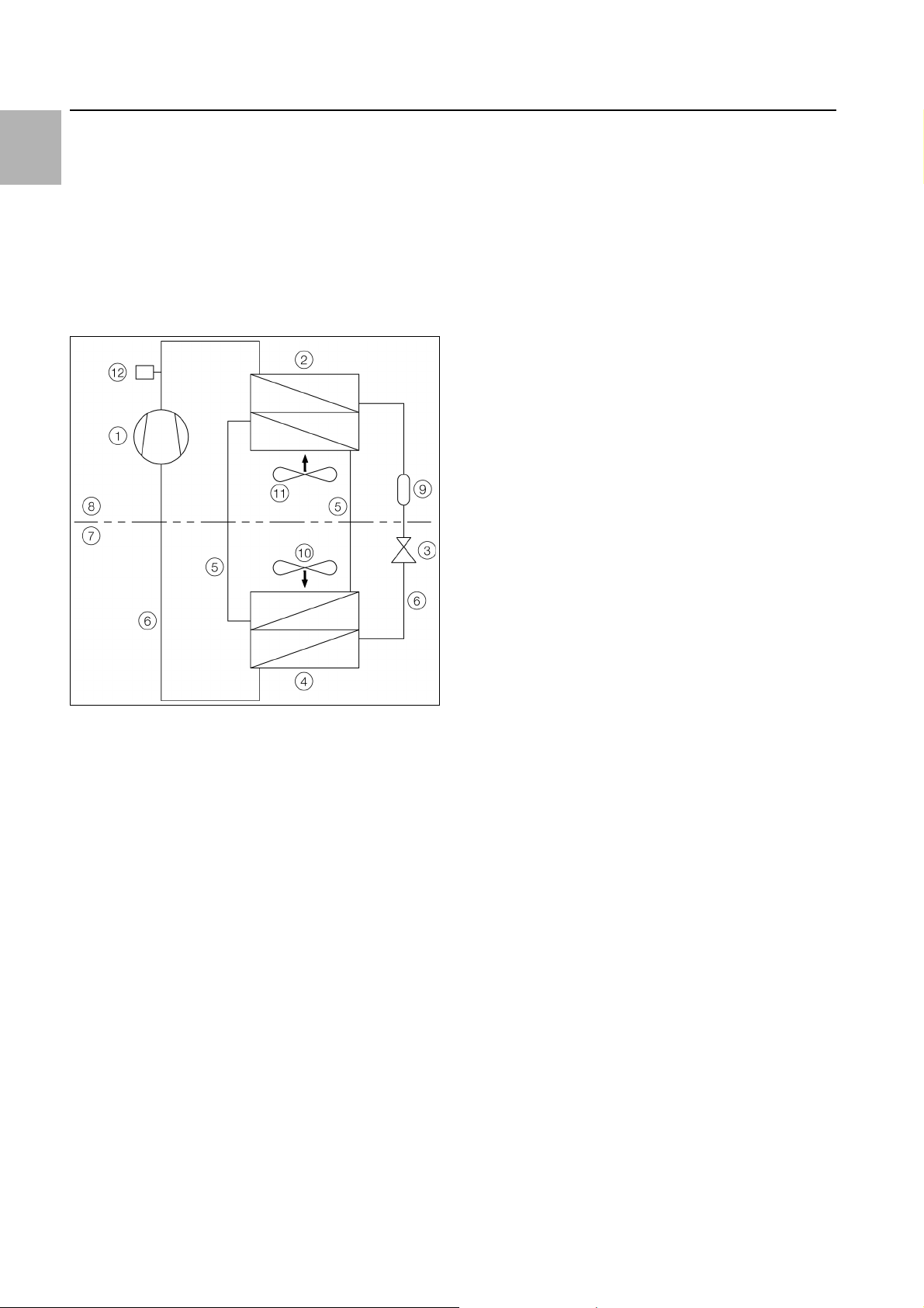
Fig. 1: Cooling circuit
Key
1 Compressor
2 Condenser (dual version) with fan
3Expansion valve
4 Evaporator coil (dual version) with fan
5 Refrigerant circuit with heat pipe
6 Refrigerant circuit with compression system
7 Internal circuit
8 External circuit
9 Dryer/collector
10 Internal fan
11 External fan
12 PSA
H
pressure monitor
In both cooling circuits, the individual components are
connected with pipes in which the refrigerant R134a is
circulating. This refrigerant is very environmentally friendly, thanks to the following properties:
–Chlorine-free
– Does not deplete the ozone layer (ozone destruction
potential ODP = 0)
Refrigerant circuit with heat pipe
The additional second refrigerant circuit operates without a compressor, expansion valve or other control elements, and is integrated into the evaporator coil and
condenser as a heat pipe.
The refrigerant inside the heat pipe (R134a) absorbs
thermal energy from the intake of enclosure air and
evaporates. The gaseous refrigerant then rises through
the pipeline until it reaches the condenser. The refrigerant is cooled down again in the condenser (provided Tu
< Ti), and the heat released is emitted into the environment. Gravity then causes the liquid refrigerant to flow
back down the pipelines. The whole cycle begins again.
6 Rittal enclosure cooling unit
Page 7
3 Product description
3.1.2 Components
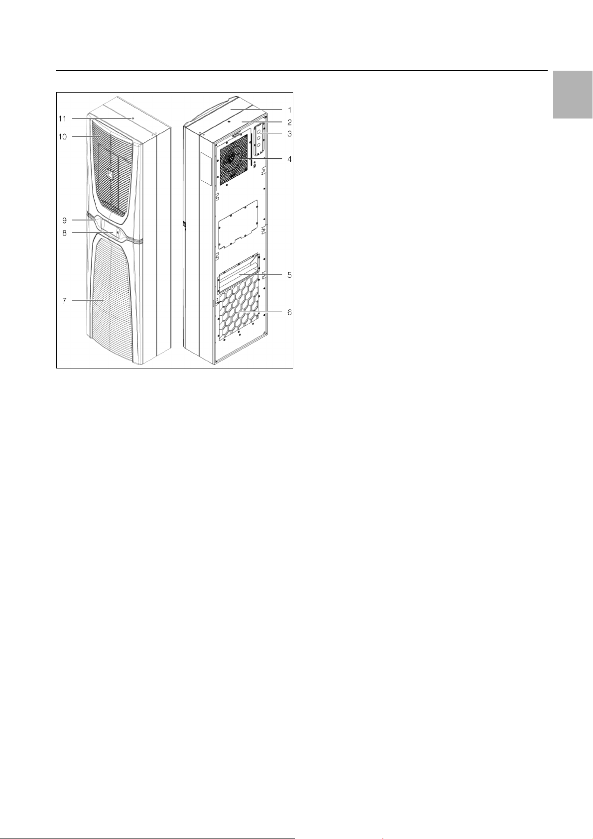
Fig. 2: Main components of cooling unit
Key
1Cover
2 Chassis
3 Connection box
4Evaporator fan
5Handle
6 Air outlet opening
7 Lower louvred grille for air inlet
8Display
9 Infill panel
10 Upper louvred grille for air outlet
11 Thread for eyebolt
3.1.3 Control
Rittal enclosure cooling units are fitted with a controller
for setting the functions of the cooling unit.
Operation using this controller is described in section 7
"Operation".
3.1.4 Safety devices
– In the refrigerant circuit, the cooling units have a type-
tested pressure monitor (to EN 12263) which switches
off the cooling unit if the maximum admissible pressure is exceeded. Once the pressure drops back below the admissible pressure, the unit will automatically
resume operation.
– Temperature monitoring prevents the evaporator coil
from icing over. If there is a risk of icing, the compressor switches itself off and automatically switches itself
back on again at higher temperatures.
– The compressor is monitored and protected by the in-
verter to prevent overloading.
– The fans have a built-in overload protection with auto-
matic reset.
– In order to allow a reduction of pressure inside the
compressor and hence a safe restart, once it has been
switched off (e.g. upon reaching the set temperature
via the door limit switch function or via de-energising),
the device will switch back on with a delay of 180 seconds.
– The device has floating contacts on the connection
pins on terminals 1 and 3 of the signal connector (X2),
via which system messages from the device may be
polled, e.g. using a PLC (2 x normally closed or normally open contacts).
3.1.5 Condensation
At high levels of humidity and low temperatures inside
the enclosure, condensate water may form on the evaporator coil.
The cooling units have an automatic electrical condensate water evaporator. The thermal component used for
this purpose is based on self-regulating PTC technology. Condensate water arising on the evaporator coil is
collected in a tank in the external circuit of the cooling
unit, and partially evaporated via the airflow. When the
water level rises, the water enters the PTC thermal component and is evaporated (through-flow heater principle). The water vapour streams out of the cooling unit
with the airflow from the external fan.
The PTC thermal component is activated automatically
when the compressor is running, and continues to run
for around 15 minutes after the compressor has been
switched off. During the after-run phase, the condenser
fan will likewise continue to run at low speed.
In the event of a short-circuit in the PTC component or if
there is a risk of inverter overload (possible at high ambient temperatures), the PTC component will be deactivated. This means that any condensate water arising
can be discharged via the safety overflow.
If the fuse has tripped, any condensate water is drained
off via the safety overflow. The condensation is routed
downwards out of the unit via a drain pipe on the evaporator coil divider panel. For this purpose, a hose may be
connected to the condensate water nozzle (see section
5.3.8 "Connect the condensate water discharge").
3.1.6 Filter mats
The entire cooling unit condenser is covered with a dirtrepelling, easy-to-clean RiNano coating. In many applications, therefore, the use of filter media is unnecessary,
particularly with dry dusts.
For dry, coarse dust and lint in the ambient air, we recommend installing an additional PU foam filter mat (available as an accessory) in the cooling unit. Depending on
the incidence of dust, you will need to replace the filter
mat from time to time (see section 8 "Inspection and
maintenance").
For oily ambient air, we recommend the use of metal filters (also available as an accessory). These may be
cleaned with suitable detergents and reused.
EN
Rittal enclosure cooling unit 7
Page 8
3 Product description
EN
3.1.7 Door limit switch
The cooling unit may be operated with a floating door
limit switch connected. The door limit switch is available
as accessory from Rittal.
The door limit switch function causes the fans and the
compressor in the cooling unit to gradually slow down
and then switch off after approximately 15 seconds
when the enclosure door is opened (contacts 1 and 2
closed). This prevents the formation of condensate water inside the enclosure while the enclosure door is
open. In order to prevent damage to the unit, it is
equipped with an ON delay: The evaporator fan will cut
in again after a delay of a few seconds on closure of the
door.
Please note that no external voltage may be applied to
the door contacts (terminals 1 and 2)
3.2 Proper use, foreseeable misuse
The cooling unit is only intended for cooling connected
enclosures. Any other use is not permitted.
– The unit must not be installed and operated in loca-
tions which are accessible to the general public (see
DIN EN 60335-2-40, paragraph 3.119).
– The unit is designed solely for stationary use.
– The manufacturer's consent must be obtained in ad-
vance for mobile applications, e.g. on cranes.
The cooling unit is state of the art and built according to
recognised safety regulations. Nevertheless, improper
use can pose a threat to the life and limb of the user or
third parties, or result in possible damage to the system
and other property.
3.3 Supply includes
Qty. Description
1 Enclosure cooling unit
1 Shipping bag with
1 – Declaration of conformity
1 – Assembly and installation instructions
1 – Assembly, installation and operating in-
structions on digital data carrier
1 – Warning and safety notes
6 – Grub screws M8 x 40 mm
6 – Nut-and-washer assembly M8
1 – Sealing tape 10 x 10 mm, L = 4.1 m
1 – Signal connector X2
1–Connector X1
1 – Cover for connection unit
1 – Membrane entry grommet
1 – Clip
1 – Wedge element
6 – Fixing clamps
4 – Corner bracket for internal/external
mounting
2 – L-shaped brackets
Consequently, the cooling unit must only be used properly and in a technically sound condition! Any malfunctions which impair safety should be rectified immediately.
Proper use also includes the observance of the documentation provided, and compliance with the inspection
and maintenance conditions.
Rittal GmbH & Co. KG is not liable for any damage which
may result from failure to comply with the documentation provided. The same applies to failure to comply with
the valid documentation for any accessories used.
Inappropriate use may be dangerous. Examples of inappropriate include:
– Use of the cooling unit over long periods with the en-
closure open.
– Use of impermissible tools.
– Improper operation.
– Improper rectification of malfunctions.
– Use of accessories not approved by Rittal GmbH &
Co. KG.
1–Earth clamp 4 NS
1–Earth clamp 5 NS
1 – Washer for attaching the earth clamp
1 – Contact washer for attaching the earth
clamp
1 – M4 nut for attaching the earth clamp
1 – Cable gland M20 x 1.5 mm
1 – EMC cable gland M20 x 1.5 mm
1 – Strain relief
Tab. 1: Supply includes
8 Rittal enclosure cooling unit
Page 9
4 Transport and handling
4.1 Delivery
The cooling unit is supplied in one packaging unit.
Check the packaging carefully for signs of damage.
Traces of oil on damaged packaging indicate a loss of
refrigerant and/or a leak in the cooling unit. Any packaging damage may be the cause of a subsequent
functional failure.
4.2 Unpacking
Remove the packaging materials from the cooling unit.
Note:
After unpacking, the packaging materials
must be disposed of in an environmentally
friendly way.
Check the cooling unit for any damage that may have
occurred during transport.
Note:
Damage and other faults, e.g. incomplete delivery, should be reported immediately, in
writing, to the shipping company and to Rittal
GmbH & Co. KG.
4 Transport and handling
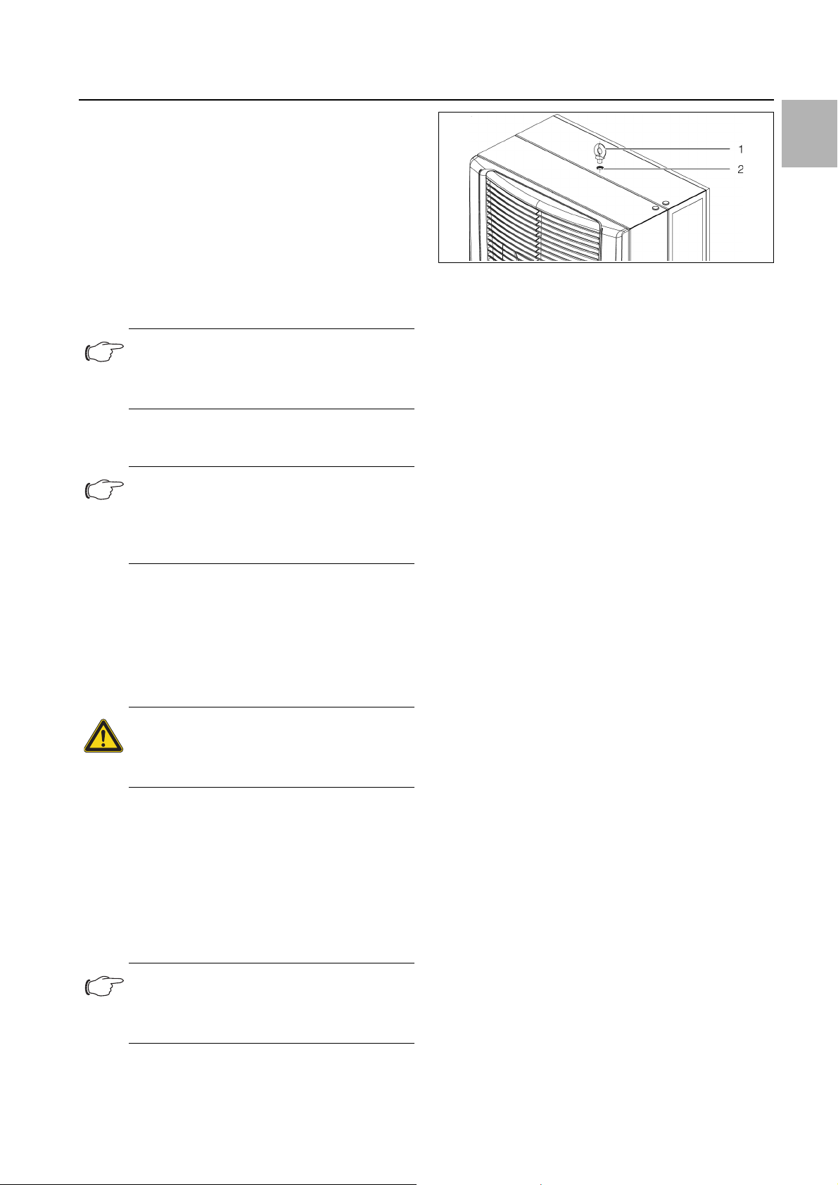
Fig. 3: Thread and eyebolt on top of the chassis
Key
1Eyebolt
2 M12 thread
Before transporting by crane, please ensure that the
lifting gear and crane have sufficient load capacity to
transport the cooling unit safely.
Never allow anyone to stand beneath a suspended
load, even for a short time, during transportation by
crane.
Protect the lifting gear on the crane hook from load deflection, because the load's centre of gravity may be
off-centre.
First position the cooling unit close to the installation
site and protect from accidentally being knocked over.
EN
Check the supply contents for completeness (see section 3.3 "Supply includes").
4.3 Transport
Depending on the chosen version, the cooling unit may
weigh up to 85 kg. The components in the cooling unit
chassis account for the bulk of the weight.
Warning!
Please note the maximum weights that
may be lifted by individuals. It may be
necessary to use lifting gear.
At the rear of the cooling unit is a handle which can be
used to briefly lift the cooling unit when inserting into the
mounting cut-out.
There is also an M12 thread at the top of the chassis,
into which a Rittal eyebolt (e.g. belonging to an enclosure) may be screw-fastened. The cooling unit is readily
transported with the aid of lifting gear and an indoor
crane.
Note:
An eyebolt with M12 thread may be ordered
as an accessory from Rittal (see section 13
"Accessories").
Rittal enclosure cooling unit 9
Page 10
5 Installation
EN
5 Installation
5.1 Safety instructions
Warning!
Please note the maximum weights that
may be lifted by individuals. It may be
necessary to use lifting gear.
Warning!
Work on electrical systems or equipment may only be carried out by an electrician or by trained personnel under the
guidance and supervision of an electrician. All work must be carried out in accordance with electrical engineering
regulations.
The cooling unit may only be connected
after the aforementioned personnel have
read this information!
Use only insulated tools.
Follow the connection regulations of the
appropriate electrical supply company.
The cooling unit must be connected to
the mains via an all-pin isolating device
to overvoltage category III (IEC 61058).
The cooling unit is not de-energised until
all of the voltage sources have been disconnected!
– The installation site must be free from excessive dirt,
aggressive ambient conditions and moisture.
– The ambient temperature must not exceed 60°C.
– It must be possible to fit a condensate water discharge
(see section 5.3.8 "Connect the condensate water
discharge").
– The mains connection data as stated on the rating
plate of the cooling unit must be guaranteed.
Size of installation room
– Units SK 3186930 and SK 3187930 must not be in-
stalled in rooms of less than 6 m³.
– Units SK 3188940 and SK 3189940 must not be in-
stalled in rooms of less than 12 m³.
Electromagnetic interference (EMI)
– Interfering electrical installations (high frequency) must
be avoided.
5.3 Assembly procedure
5.3.1 Assembly instructions
Before assembling, please ensure that the enclosure
is sealed on all sides (IP 54). Increased condensation
will occur later during operation if the enclosure is not
airtight.
If applicable, additionally fit a door limit switch (such as
4127.010) to the enclosure which switches off the
cooling unit when the enclosure door is opened to pre-
vent excessive condensation (see section 3.1.7 "Door
limit switch").
Please ensure that the electronic assemblies in the en-
closure allow the even circulation of air.
Please be sure to observe the applicable regulations
governing electrical installations of the country in
which the device is installed and operated, as well as
national regulations for accident prevention. Please
also observe any internal company regulations, such
as work, operating and safety regulations.
The technical specifications and limit values stated
must not be exceeded under any circumstances. In
particular, this applies to the specified ambient temperature range and IP protection category.
5.2 Siting location requirements
When choosing the installation site for the enclosure,
please observe the following:
– The site for the enclosure, and hence the positioning
of the cooling unit, must be carefully selected so as to
ensure good ventilation (clearance between cooling
units and clearance between a cooling unit and the
wall must be at least 200 mm in each case).
– The cooling unit must be installed and operated with a
maximum deviation of 2° from the vertical.
10 Rittal enclosure cooling unit
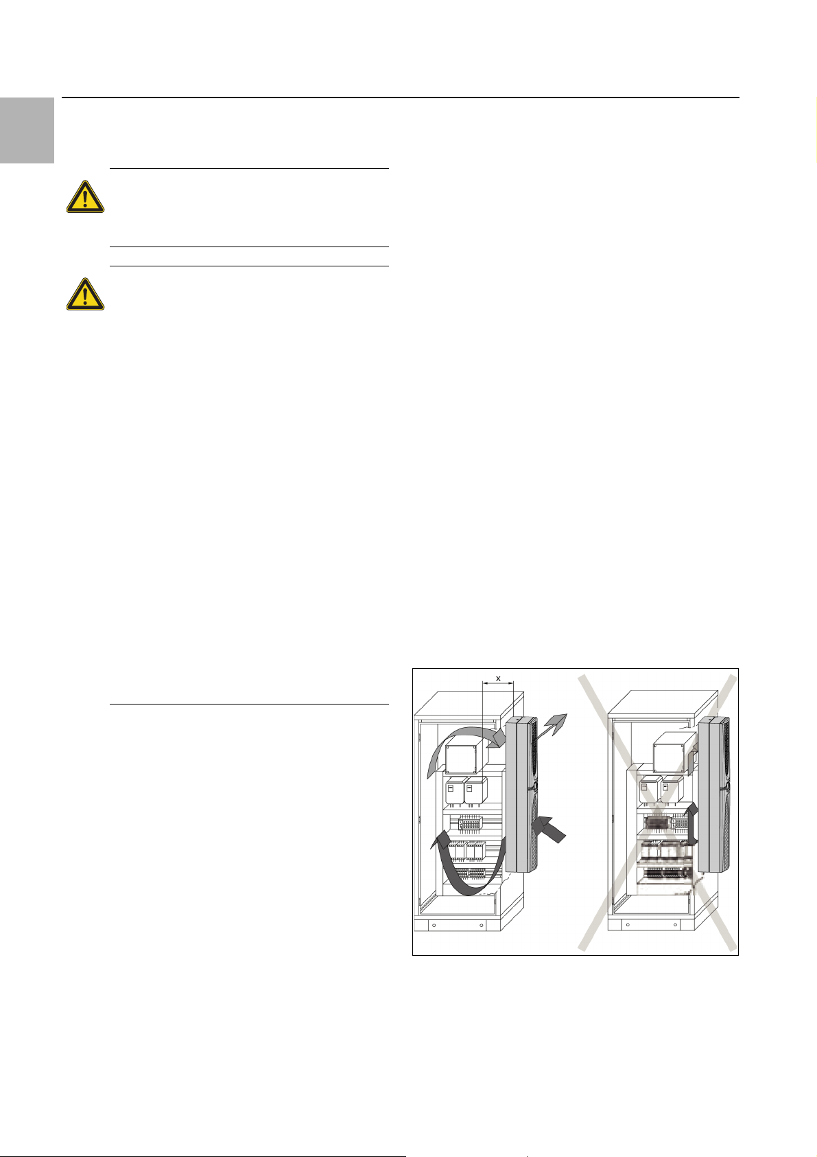
Fig. 4: Never direct the cold airflow at active components
Page 11
Under no circumstances should the air inlet and outlet
openings of the cooling unit be obstructed. Only in this
way is it possible to ensure that the maximum cooling
output is available.
Please ensure that the cold airflow from the cooling
unit is not directed at active components.
Fig. 5: Never direct the cold airflow at active components
If appropriate, install components to divert the air.
When installing in a dismantled door or side panel,
please ensure that it cannot fall over when installing
the cooling unit in the mounting cut-out.
Note:
The pictures in this chapter illustrate the in-
stallation of the cooling unit in an enclosure
door. Installation in a side panel is carried out
in the same way.
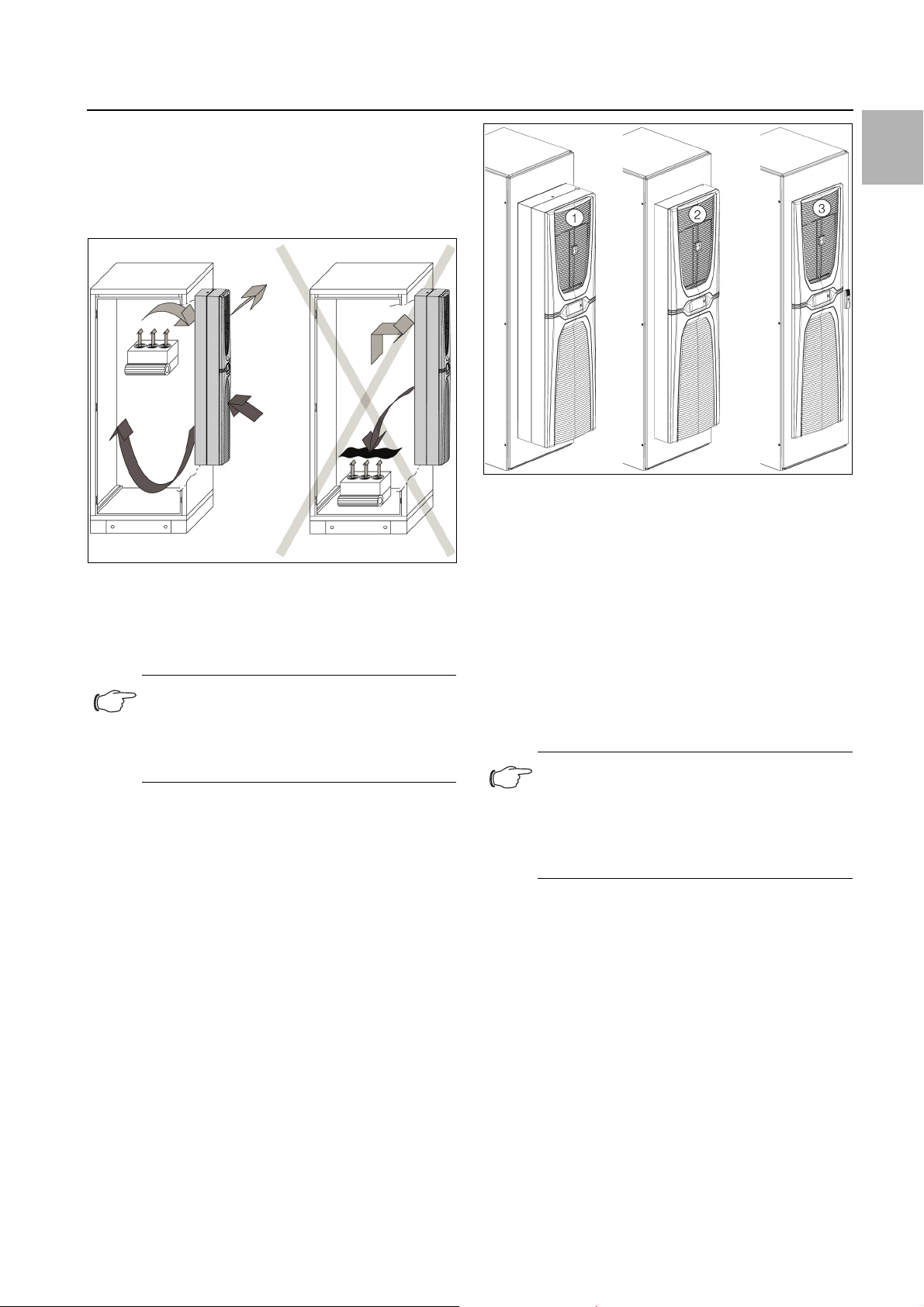
5.3.2 Mounting options
In principle, there are three different options for installing
the cooling unit on an enclosure door or side panel.
5 Installation
EN
Fig. 6: Mounting options
Key
1 External mounting
2 Partial internal mounting
3 Full internal mounting
– External mounting: All of the cooling unit is outside the
enclosure.
– Partial internal mounting The cooling unit chassis is in-
side the enclosure, while the cover and the louvred
grilles are outside.
– Full internal mounting: All of the cooling unit is inside
the enclosure. Only the louvred grilles project on the
outside.
Note:
– Full installation of the 6 kW cooling unit is
not possible.
– On an enclosure with 500 mm depth, the
unit may only be externally mounted on the
side panel.
Your chosen installation option will ultimately depend on
how much space you require inside and outside of the
enclosure. The various mounting options have no influence on the cooling output of the cooling unit, which remains the same in all cases.
– If there are a large number of components installed in-
side the enclosure, external mounting or partial internal mounting of the cooling unit may be appropriate. In such cases, the space inside the enclosure may
be insufficient for full internal mounting, or it may not
be possible to guarantee adequate cooling of all components inside the enclosure.
– If the space surrounding the enclosure is limited,
full internal mounting may be suitable, so as to keep
essential escape routes clear.
Rittal enclosure cooling unit 11
Page 12
EN
5 Installation
5.3.3 Make a mounting cut-out in the enclosure
In order to mount the cooling unit on the enclosure, a
suitable mounting cut-out must be made in the door or
side panel of the enclosure. In principle, the mounting
cut-out is identical for all three mounting options. A special mounting cut-out is only required for external mounting on the side panel of a 500 mm deep enclosure.
Note:
The dimensions of the mounting cut-outs
can be found in section 12.1 "Representation
of mounting cut-outs".
Using the diagrams in section 12.1 "Representation of
mounting cut-outs", calculate the required dimensions
for your mounting cut-out .
Drill all the required holes and make the mounting cutout.
Carefully deburr all drilled holes and the cut-out to prevent injuries caused by sharp edges.
Caution!
Drilled holes and cut-outs that have not
been fully deburred may cause cut injuries, particularly when assembling the
cooling unit.
5.3.4 External mounting of the cooling unit
Note:
The description in this section does not ap-
ply to external mounting of the cooling unit on
the side panel of a 500 mm deep enclosure.
This is described in section 5.3.5 "Mounting
the cooling unit externally on a 500 mm deep
enclosure".
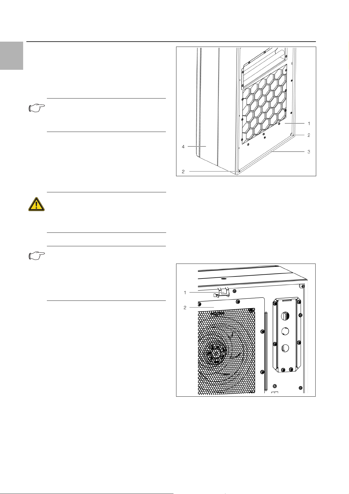
Fig. 7: Threaded bolts at the rear of the cooling unit
Key
1 Rear of cooling unit
2 Lower threaded bolt
3 Joint of sealing tape
4Cover
Push the clip included with the supply into the relevant
hole at the top edge of the cooling unit at the rear.
This clip will prevent the cooling unit from falling out of
the mounting cut-out later on if it is not yet adequately
secured with the threaded bolt.
Cut the sealing tape in the dispatch bag to the required length so that it can be placed all the way round
the rear of the cooling unit once.
Start by positioning the sealing tape on the bottom
edge, so that the joint between the two ends of the
sealing tape is likewise on the lower edge of the unit.
Carefully stick the sealing tape as close to the edge as
possible on the rear of the cooling unit.
Screw the four threaded bolts into the blind nuts in the
corners at the rear of the cooling unit.
Fig. 8: Clip at the rear of the cooling unit
Key
1 Clip
2 Rear of cooling unit
12 Rittal enclosure cooling unit
Page 13
Lift up the cooling unit, preferably from a lifting eye using suitable lifting gear, and initially set the cooling unit
down with the two bottom threaded bolts on the door
or side panel of the enclosure.
If transportation by crane is not possible, lift the cooling unit into the mounting cut-out in the same way using the handle.
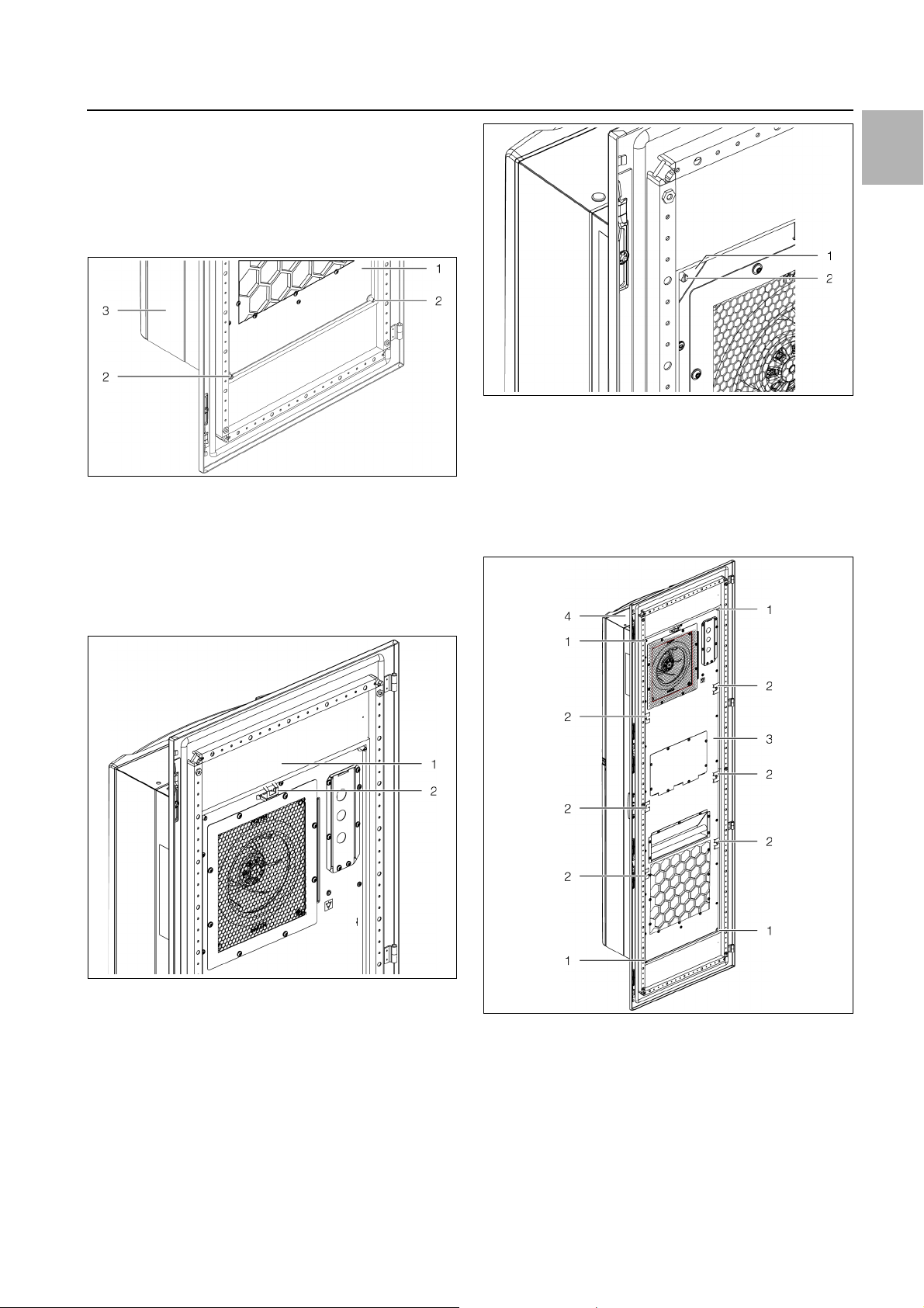
Fig. 9: Threaded bolt in door cut-out
Key
1 Inside of enclosure door
2 Threaded bolts at bottom (2x)
3 Cooling unit on the outside of the enclosure door
5 Installation
Fig. 11: Corner brackets on the threaded bolts
Key
1Corner bracket
2 Threaded bolt
Next, attach the two corner brackets to the threaded
bolts at the bottom and secure with the corresponding
nuts.
EN
Slide the cooling unit into the mounting cut-out at the
top until the clip behind the cut-out latches home.
Fig. 10: Clip in mounting cut-out
Key
1 Inside of enclosure door
2 Clip
Attach the two corner brackets to the threaded bolts
at the top and secure with the corresponding nuts.
Fig. 12: Threaded bolts at rear
Key
1 Threaded bolts (4x)
2 Fastening clamps (6x)
3 Rear of cooling unit
4 Cooling unit in front of enclosure door
Insert the six fastening clamps into the rear of the cool-
ing unit.
Rittal enclosure cooling unit 13
Page 14
5 Installation
EN
These fastening clamps ensure that the cooling unit is
directly in contact with the mounting cut-out of the enclosure door over the entire height.
If applicable, re-attach the door or side panel including
cooling unit to the enclosure, if not mounted directly
on the enclosure.
5.3.5 Mounting the cooling unit externally on a 500 mm deep enclosure
Note:
The description in this section applies to ex-
ternal mounting of the cooling unit on the
side panel of a 500 mm deep enclosure. External mounting on deeper enclosures is also
possible with this type of installation.
In principle, external mounting on the side panel is carried out in the same way as described in section 5.3.4
"External mounting of the cooling unit". However, please
note the following differences:
– Six threaded bolts are required for installation, rather
than four.
5.3.6 Partial internal mounting of the cooling unit
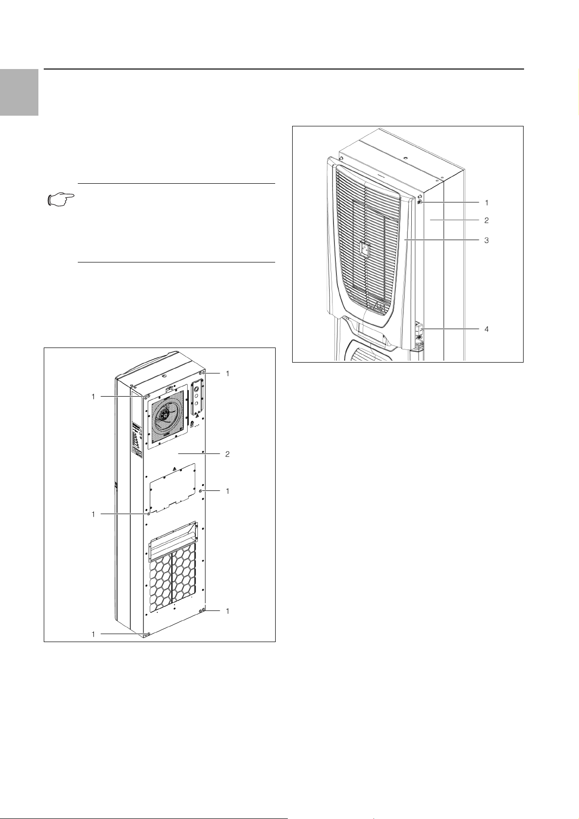
At the front of the cooling unit, pull the top louvred
grille away from the mounting clips on the cover, and
place or lay it down somewhere safe.
Fig. 13: Threaded bolts at rear
Key
1 Threaded bolts (6x)
2 Rear of cooling unit
Fig. 14: Remove the top louvred grille
Key
1Mounting clip
2Cover
3 Top louvred grille
4 Infill panel on cooling unit
Flip open the bottom louvred grille below the infill pan-
el.
Release the two stays in the hinge mechanism at the
top from the brackets attached to the cover of the
cooling unit.
– The unit with the threaded bolts is lowered into the rel-
evant holes, rather than on the mounting cut-out.
– No fastening clamps are fitted into the rear of the unit.
14 Rittal enclosure cooling unit
Page 15
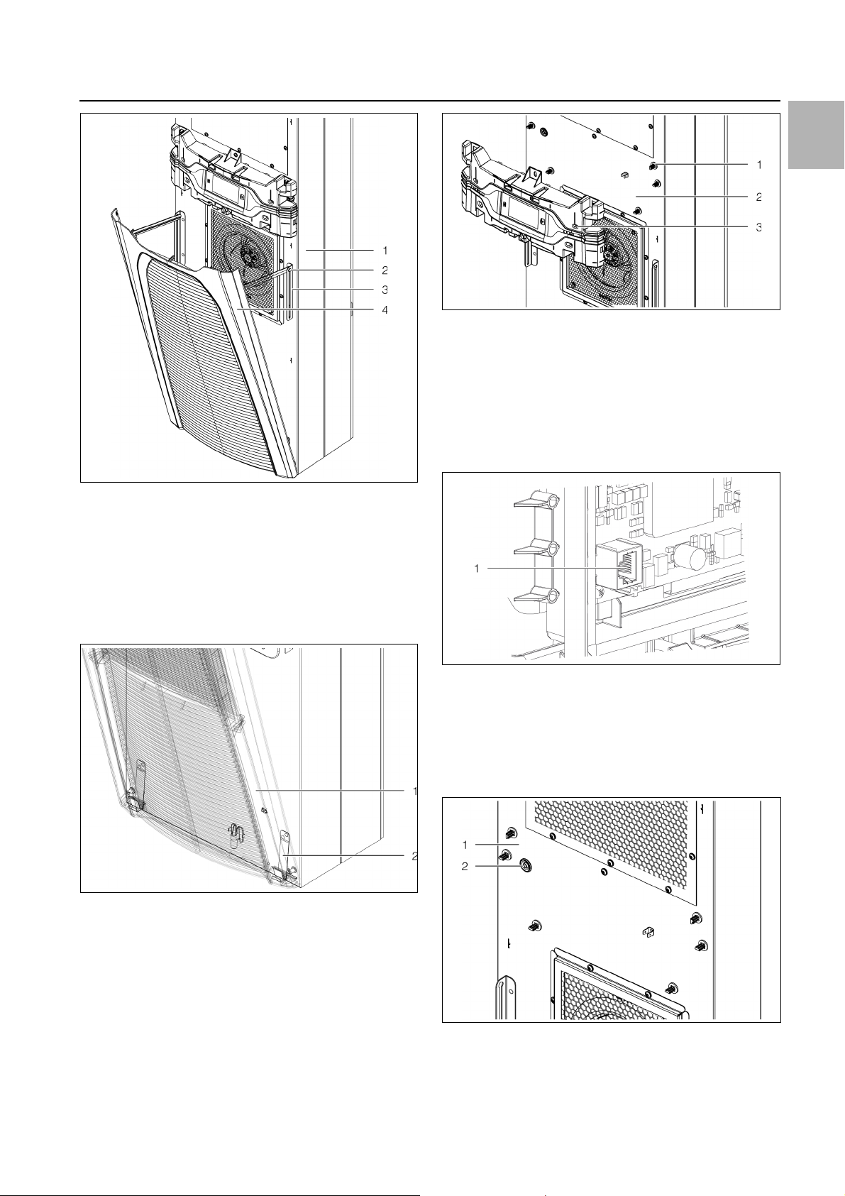
Fig. 15: Attachments on hinge mechanism
Key
1Cover
2 Stays in hinge mechanism
3 Bracket
4 Bottom louvred grille
5 Installation
Fig. 17: Remove the infill panel
Key
1 Mounting clips
2Cover
3 Infill panel
On the rear of the display, disconnect both of the con-
nectors (PE conductor and connection) and remove
the infill panel completely from the cooling unit.
EN
Pull the bottom louvred grille forwards out of its hold-
ers, and place or lay it down somewhere safe.
Fig. 16: Bottom holders of louvred grille
Key
1 Bottom louvred grille
2Holders
Gently pull the infill panel including display forwards to
release it from the mounting clips on the cover.
Fig. 18: Connection point on the rear of the cooling unit
Key
1 Connection point
Place the infill panel somewhere safe.
Carefully push the connector including connection cable inwards through the cable gland in the cover.
Fig. 19: Cable gland in the cover
Key
1Cover
2 Cable gland
Rittal enclosure cooling unit 15
Page 16

5 Installation
EN
Caution!
The cooling unit will only be stable as
long as the cover and chassis are connected. For this reason, be sure to brace
the chassis, in particular, to prevent it
from falling over before removing the
cover.
Loosen the four threaded bolts in the corners of the
cover which connect the cover to the chassis.
Carefully pull the cover forwards (approx. 5 cm) from
the chassis.
The PE conductor connection between the cover and
the chassis is located on the right-hand side, approximately halfway up.
Fig. 21: Clip on the top edge of the chassis
Key
1Chassis
2 Clip in chassis
3 Seal
Lift up the chassis, preferably with a lifting eye using
suitable lifting gear, and insert it into the mounting cutout in the door or side panel of the enclosure from the
inside with the edge fold at the bottom of the chassis.
If transportation by crane is not possible, lift the chassis into the mounting cut-out in the same way using
the handle.
Fig. 20: PE conductor connection (viewed from behind)
Key
1 PE conductor connection, cover
2 PE conductor connection, chassis
Pull the flat-pin connector of the PE conductor off in-
wards, preferable on the chassis.
Remove the cover completely from the chassis, and
place or lay it down somewhere safe.
There is a clip prefitted to the top edge of the chassis
on the front. This clip will later prevent the chassis from
falling out of the mounting cut-out before it is properly
secured with the threaded bolt.
Fig. 22: Edge fold at bottom of chassis
Key
1 Edge fold on chassis (towards cover)
2 Outside of enclosure door
Push the chassis into the mounting cut-out at the top
until the clip behind the cut-out latches home.
16 Rittal enclosure cooling unit
Page 17

Fig. 23: Clip on the top edge of the chassis
Key
1 Outside of enclosure door
2 Clip in chassis
Make sure that the clip behind the cut-out is fully
snapped in towards the top.
5 Installation
Slide the flat-pin connector of the PE conductor into
place, and ensure that the cover and chassis are connected.
Warning!
The PE conductor which connects the
cover and the chassis must be connected to both connectors in all cases. Otherwise, there is a risk of injury from
electric shock if the unit connection was
faulty or defective.
Place the cover fully over the chassis, and connect the
cover and the chassis using the four threaded bolts in
the corners of the cover.
EN
Fig. 24: Mounting of the wedge element
Key
1 Outside of enclosure door
2 Clip in chassis
3 Wedge element
Please also insert the wedge element from the exterior
up to the stop in order to fasten the clip in the upper
position.
Fig. 25: Fully inserted wedge element
Set the cover down at the front near the chassis, and
thread the connection cable of the display outwards
through the cable gland in the cover.
Fig. 26: Cover on the chassis
Key
1 Threaded bolts (4x)
2 Outside of enclosure door
3Chassis
4Cover
Connect the display to the connector and insert the
entire infill panel on the cooling unit.
Place the bottom louvred grille onto the holders and
secure the two stays at the top of the hinge mechanism into the brackets attached to the cover of the
cooling unit.
Finally, replace the top louvred grille onto the cover.
If applicable, re-attach the door or side panel including
cooling unit to the enclosure, if not assembled directly
on the enclosure.
Rittal enclosure cooling unit 17
Page 18

EN
5 Installation
5.3.7 Full internal mounting of the cooling unit
First, dismantle the top and bottom louvred grilles as
well as the infill panel and the display in the same way
as for partial internal mounting (see section 5.3.6 "Partial internal mounting of the cooling unit").
Cut the sealing tape in the dispatch bag to the required length so that it can be placed all the way round
the cover once.
Start sticking the sealing tape at the bottom edge, so
that the joint between the two ends of the sealing tape
is likewise on the bottom edge of the unit.
Carefully stick the sealing tape as close as possible to
the edge of the cover.
On the front top edge of the cover, push the clip included with the supply into the relevant hole.
This clip will prevent the cooling unit from falling out of
the mounting cut-out later on before it is properly secured with the threaded bolt.
Fig. 28: Bracket at the bottom of the cover
Key
1 Bracket in mounting cut-out
2 Outside of door
Push the cooling unit into the mounting cut-out at the
top until the clip behind the cut-out latches home.
Fig. 27: Clip at top edge of cover
Key
1Cover
2 Clip on the cover
Lift up the cooling unit, preferably with a lifting eye us-
ing suitable lifting gear, and insert it into the mounting
cut-out in the door or side panel of the enclosure with
the two brackets at the bottom of the cover.
If transportation by crane is not possible, lift the cooling unit into the mounting cut-out in the same way using the handle.
Fig. 29: Clip at top edge of cooling unit
Key
1 Outside of enclosure door
2 Clip in mounting cut-out
Mount the corner brackets onto the top two threaded
bolts from the outside.
18 Rittal enclosure cooling unit
Page 19

Fig. 30: Corner brackets on top threaded bolts
Key
1 Threaded bolt
2Corner bracket
Mount the L-shaped brackets onto the bottom two
threaded bolts from the outside.
5 Installation
EN
Fig. 31: L-shaped brackets on bottom threaded bolts
Key
1 L-shaped bracket
2 Threaded bolt
Next, working from the outside of the enclosure, se-
cure the four threaded bolts in the corners of the cover
using the corresponding nuts from the dispatch bag.
Fig. 32: Mounting points on cooling unit
Key
1 Threaded bolts with nuts (4x)
2 Fastening clamps
3 Cooling unit behind enclosure door
4 Front of cooling unit (without louvred grille)
Insert the six fastening clamps into the cover of the
cooling unit.
These fastening clamps ensure that the cooling unit is
directly in contact with the mounting cut-out of the enclosure door over the entire height.
Connect the display to the connector and fit the entire
infill panel to the cooling unit.
Place the bottom louvred grilles onto the holders and
secure the two stays of the top hinge mechanism into
the brackets attached to the cooling unit cover.
Finally, replace the top louvred grille onto the cover.
If applicable, re-attach the door or side panel including
cooling unit to the enclosure if not mounting directly on
the enclosure.
5.3.8 Connect the condensate water discharge
There is a condensate water evaporator fitted in the external circuit of the cooling unit. With an enclosure connected, this condensate water evaporator may typically
evaporate condensate water volumes of up to 100 ml/h.
If larger quantities of condensate water are produced, a
condensate water discharge hose may additionally be
fitted. This hose allows condensate water to be routed
out of the cooling unit pressurelessly. A suitable hose is
available as an accessory from Rittal (see section 13
"Accessories").
Please follow the instructions given below:
Rittal enclosure cooling unit 19
Page 20

5 Installation
EN
– The hose must be laid with an adequate and constant
gradient to prevent siphoning.
– The hose must be laid without any kinks.
– If extended, the cross-section of the hose must not be
reduced.
– The hose should be routed to a drain or external con-
densate water evaporator by the customer.
Fig. 33: Connection for condensate water discharge hose
Key
1 Connection point
2 Hole in enclosure for hose
rated values may be taken from section 10 "Technical
specifications" below.
– Low-noise potential equalisation must be guaranteed
with the mains connection.
– In order to prevent EMC interference, the unit should
be incorporated into the existing potential equalisation
system with a larger cable cross-section (10 mm²).
Overvoltage protection and supply line load
– The unit does not have its own overvoltage protection.
Measures must be taken at the supply end by the
switchgear manufacturer or operator to ensure effective protection against lightning and overvoltage. The
limits specified in standard UL/IEC/EN 60335-2-40
must be observed.
– The units are classified as overvoltage category III. The
mains voltage must not deviate by more than the tolerance specified in section 10 "Technical specifica-
tions".
– The discharge current may exceed 3.5 mA.
– The units are high-voltage tested ex works. An addi-
tional high voltage test must only be carried out with a
DC voltage supply source (1500 VDC max.).
Connect a suitable hose to the condensate water discharge nozzle and secure using a hose clip.
Lay the hose as per the instructions above.
5.4 Electrical connection
5.4.1 Notes on electrical installation
When carrying out the electrical installation, it is important to observe all valid national and regional regulations as well as the provisions of the responsible
power supply company.
– Electrical installation must only be carried out by a
qualified electrician who is responsible for compliance
with the existing standards and regulations.
– The mains infeed and the signal cable must be of a
shielded design. The shielding can be connected to
the earth lug provided in the connection area of the
mains connector.
– All cables routed into the wiring compartment have to
be insulated for the maximum voltage of the power
supply.
Connection data
– The connected voltage and frequency must corre-
spond to the ranges stated on the rating plate. The
units support multiple voltages.
– The cooling unit must be connected to the mains via
an all-pole disconnect to overvoltage category III (IEC
61058-1).
– No additional temperature control may be connected
upstream of the unit at the supply end
– Install a pre-fuse to match the supply voltage used and
the specific electrical output of the cooling unit. The
Three-phase devices
– There is no need to observe a counterclockwise or
clockwise phase rotation when making the electrical
connection for inverter devices in the three-phase ver-
sion. The electronics incorporated into the devices au-
tomatically create the required phase rotation.
– In three-phase devices, the absence of a phase is de-
tected, and the device is switched off.
– Outgoing equipment is monitored by the inverter, and
deactivated in the event of a malfunction in the elec-
tricity supply.
Door limit switch
– Each door limit switch can only be assigned to one
cooling unit.
– Several door limit switches may be operated in parallel
with one cooling unit.
– The minimum cross-section for the connection cable
is 0.3 mm² for a cable length of 2 m.
– The line resistance to the door limit switch must not
exceed a maximum of 50 Ω.
– The maximum admissible line length is 10 m.
– The door limit switch only supports a floating connec-
tion; no external voltages.
– The contact of the door limit switch must be closed
when the door is open.
– The safety extra-low voltage for the door limit switch is
provided by the internal power pack: Current approx.
5mA DC.
Connect the door limit switch to terminals 5 and 6 of
the signal connector.
20 Rittal enclosure cooling unit
Page 21

Fig. 34: Connections at rear
Key
1 Connection for communication module (X3)
2 Connection for signal connector (X2)
3 Connection for mains connector (X1)
4 Bolt (here with fitted earth clamp)
Potential equalisation
If the unit is to be integrated into the customer's existing
potential equalisation system for EMC reasons, a conductor with a larger nominal cross-section of at least
10 mm² can be connected to the potential equalisation
connection point (attachment points) on wall-mounted
cooling units. The connection point is labelled with the
required switch symbol.
5 Installation
Fig. 36: Potential equalisation arrangement
Key
1 Ring terminal with PE conductor
2 Contact washer
3Washer
4 Screw
Note:
According to the standard, the PE conductor
in the mains connection cable is not classed
as an equipotential bonding conductor.
5.4.2 Install the power supply
Note:
– The mains supply must be of a shielded
design with preferred EMC types in order
to achieve the values required by the
standard.
– The earth clamp may be used to contact
the cable shielding with the enclosure inside the connection box (fig. 34, item 4).
Remove the mains connector from the dispatch bag
and connect to the mains as shown on the connection
diagram (fig. 37 or fig. 38).
EN
Fig. 37: Circuit diagram SK 3186930 and SK 3187930
Fig. 35: Connection point for potential equalisation
Key
1 Connection point
Attach the potential equalisation to the unit's connec-
tion point using the screw, washer and contact washer.
Rittal enclosure cooling unit 21
Page 22

EN
5 Installation
Fig. 38: Circuit diagram SK 3188940 and SK 3189940
There is also a cover for the connection box included in
the dispatch bag.
Insert the EMC cable gland included with the supply
into the openings in the cover to ensure adequate
strain relief for the connection cable.
Close the connection box with the cover.
Cover any unused openings in the cover with sealing
bungs.
When connecting the cooling unit in accordance with
NFPA 70 (NEC):
Use a conduit fitting instead of the cable gland.
Use copper conductors only to connect the supply cable to the mains connector.
Micro-USB interface
A micro-USB interface is located on the front, to the right
of the display. A tablet or laptop may be connected here
for easy configuration of the unit.
Connect a tablet or laptop with installed RiDiag soft-
ware to the micro-USB interface.
No other USB devices will be detected on this connec-
tion.
RS 485 interface
An RS 485 interface is located on the rear of the connection box. The communication module with which you
can connect the cooling unit to a monitoring system
(Rittal CMC), may be connected here.
Connect the communication module (available as an
accessory) to the RS 485 interface.
Note:
A direct connection to the cooling unit via the
RS 485 interface is not possible.
NFC interface
The cooling unit may be accessed with a smartphone
app via the integral NFC interface. Access is only possible with the app supplied by Rittal.
5.4.3 Connect the alarm relays
System messages from the cooling unit may be output
to an external signal source via two floating relay outputs.
Note:
The factory setting of the relay outputs in their
de-energised state is NO (Normally Open).
Connect a suitable connection cable to the connection terminals 1 (Alarm K1) and/or 3 (Alarm K2) of the
signal connector (X2).
Configure the alarm relays you wish to use to output
error messages (see section 7.4.2 "Alarm relays").
AC
cos φ = 1
I max. = 2 A
U max. = 250 V
Tab. 2: Contact data
5.4.4 Interfaces
The cooling unit has the following interfaces for communicating with external systems:
– Micro-USB interface on the front
– RS 485 interface on the rear
–NFC interface
22 Rittal enclosure cooling unit
Page 23

6 Commissioning
Note:
The oil must collect in the compressor in or-
der to ensure adequate lubrication and cooling. For this reason, do not operate the
cooling unit for at least 30 minutes after assembling the equipment.
Observe the aforementioned waiting period of at least
30 minutes before commissioning the unit after assembly.
Next, switch on the voltage supply to the cooling unit.
The Rittal logo will initially appear on the display, followed a short time later by the start screen.
You can now make your individual settings on the unit,
e.g. set the temperature or assign the network identifier, etc. (refer to chapter 7 "Operation").
Note:
It is not necessary to carry out leak or pressure tests on the cooling unit prior to commissioning. Rittal has already done this in the
factory.
6 Commissioning
EN
Rittal enclosure cooling unit 23
Page 24

7 Operation
EN
7Operation
7.1 General
The cooling unit is equipped with a touch function display for making basic settings and displaying error messages. This is an industrial-grade touch display which is
pressure-sensitive and may therefore be operated with
gloves.
As well as operating directly on the cooling unit itself,
there is also a smartphone app available. This offers almost the same functions as the actual display, and additionally provides extended explanations of error messages, as well as the option of contacting the Rittal Service team directly.
7.2 Layout of the display
The display is divided into a top section on a dark background, and a bottom section with the menu bar. This
layout is always identical, but the content of the two sections will vary according to the menu selected.
7.2.1 Start screen
The start screen is always displayed while the cooling
unit is in normal operation, provided there are no error
messages.
Item Description Possible icons
5 USB connection (if
connected)
6 Self-test (if initiated)
7 NFC connection (max.
120 seconds after connecting)
8 Type of cooling
9 Control based on ...
10 External sensor
11 Information menu
12 System messages
(where applicable)
13 Service icon (if re-
quired)
Fig. 39: Layout of the start screen
Key
Item Description Possible icons
1 Internal temperature
display (2-digit °C/3digit °F)
2 EER scale: Range
0...20 / current average
EER value of the last 24
hours
3 Ti scale: Range 20 ...60
/ value: Average enclosure internal temperature of the last 24 hours
4 Display temperature
unit
Numbers from 0-9
14 Configuration
Tab. 3: List of all icons with descriptions
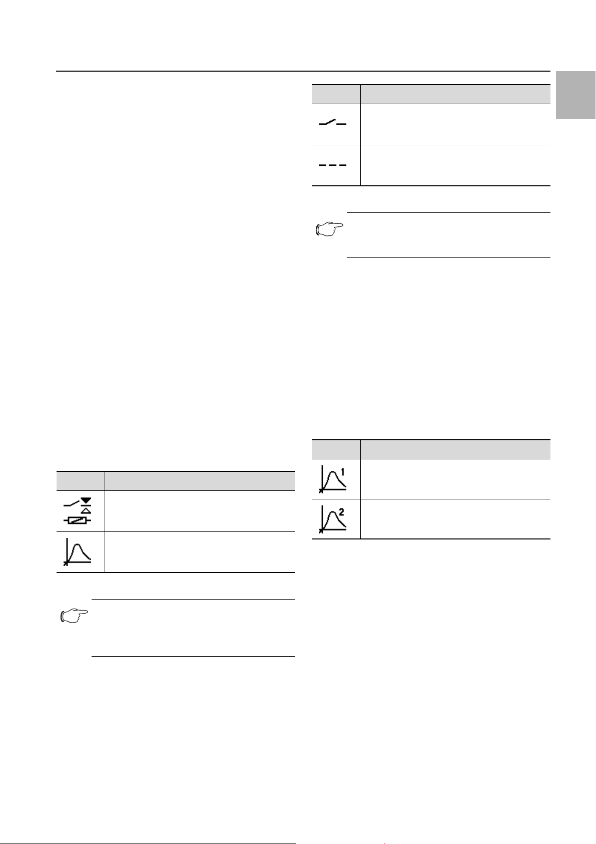
Type of cooling
The current form of cooling is indicated by one of the following four icons.
Symbol Parameters
Cooling in compressor mode without support
from the heat pipe
Cooling in compressor mode with support
from the heat pipe
Cooling via the heat pipe only
No cooling
Tab. 4: Possible icons for the current type of cooling
7.2.2 Changing a parameter value
If a parameter value is changed, the display including the
menu bar will also change.
Tab. 3: List of all icons with descriptions
24 Rittal enclosure cooling unit
Page 25

Fig. 40: Screen for changing a parameter value
Key
1Main screen
2Control bar
The currently selected parameter value is displayed in
the centre of the main screen. To change this value, you
always proceed in the same way, as described below
with the example of adjusting the set temperature:
On the start screen, click on the "Configuration" button.
Enter the PIN to gain access to the lower-level screen
pages of the "Configuration" zone.
"22" is the default PIN.
Click on the "Temperature" symbol.
Click on the "Control mode" symbol.
Select your preferred control mode from the display.
Change the setting to the required temperature using
the "Up" and "Down" arrows.
Alternatively, you can also select the one of the displayed higher or lower values directly.
Finally, confirm the set value with "OK".
Exit this screen page with the "Back" button.
7.3 Information menu
Click on the "Information" symbol to display a list of
lower-level screen pages.
Symbol Parameters
7 Operation
7.3.1 Temperature information
Click on the "Temperature information" symbol.
The ambient temperature and internal temperature are
displayed, in each case as an average for the last 24
hours of operation.
Symbol Parameter
Ambient temperature
Average ambient temperature (external temperature) over the last 24 hours of operation.
Internal temperature
Average internal temperature over the last 24
hours of operation.
Tab. 6: "Temperature information" zone
7.3.2 Device information
Click on the "Device information" symbol.
A list of general information about the device will be
displayed.
Page through the list using the "Up" and "Down" arrows.
Symbol Parameter
Serial number
Production date YYYY-MM-DD
Hardware Release x.xx.xx
Firmware Release x.xx.xx
Software Release x.xx.xx
EN
Temperature information
Device information
Efficiency information
Tab. 5: "Information" zone
Tab. 7: "Device information" zone
Rittal enclosure cooling unit 25
Last updated YYYY-MM-DD
Last serviced YYYY-MM-DD
Customer device name
Name assigned to the cooling unit by the customer. This title can be assigned using the
RiDiag software or the Blue e+ app to distinguish between individual units.
Current control mode
Page 26

7 Operation
EN
Symbol Parameter
If the unit is configured as a "slave": Slave number.
Tab. 7: "Device information" zone
7.3.3 Efficiency information
Click on the "Efficiency information" symbol.
The average energy efficiency ratio (EER) for the last
24 hours of operation will be displayed. The energy efficiency ratio is the ratio of the cooling output generated to the electrical power used.
Symbol Parameter
Efficiency information
Average energy efficiency ratio (EER) of the last
24 hours of operation.
Tab. 8: "Efficiency information" zone
7.4 Configuration menu
Click on the "Configuration" symbol.
A screen page will appear asking you to enter the PIN
in order to access the lower-level screen pages.
7.4.1 Temperature
Click on the "Temperature" symbol to display a list of
lower-level screen pages.
Symbol Parameter
Change unit
Set the unit "°C" or "°F"
Control mode
Alarm limit
Temperature limit which will trigger an alarm
message if exceeded.
Tab. 10: "Temperature" zone
Unit
All temperature values for the unit may be displayed either in degrees Celsius "°C" or degrees Fahrenheit "°F".
Click on the "Change unit" symbol.
Change the required unit ("°C" or "°F") using the "Up"
or "Down" arrows.
Confirm your entry with "OK".
Note:
"22" is preset in the factory as the default
PIN.
For the first digit, page through the digits "0" to "9" using the "Up" and "Down" arrows until the required digit
appears in the box.
Confirm your selection with "OK".
For the second digit, once again page through the digits "0" to "9" using the "Up" and "Down" arrows until
the required digit appears in the box.
Confirm your selection with "OK".
A list of lower-level screen pages will be displayed.
Symbol Parameter
Temperature
Settings for set temperature and control mode
Alarm relay
Settings for the alarm relays.
Display language
Choice of language for display texts.
Self-test
Perform a self-test.
Tab. 9: "Configuration" zone
Control mode
The cooling unit is able to control cooling output according to one of the following two temperature values:
– Internal temperature: The temperature at which air
is drawn out of the enclosure into the cooling unit.
– External sensor: The temperature measured with an
external temperature sensor at a so-called hot spot in
the enclosure.
Click on the "Control mode" symbol.
The setpoint for the currently set control mode is dis-
played.
Choose your preferred control mode by selecting it
from the display:
Symbol Parameter
Internal temperature
External sensor
Tab. 11: "Control mode" zone
The corresponding symbol for the chosen control mode
is likewise displayed on the overview page.
Note:
The external temperature sensor is available
as accessory from Rittal.
26 Rittal enclosure cooling unit
Page 27
Change the setpoint using the "Up" and "Down" arrows or select the required temperature directly.
Setting range: 20°C (68°F)…50°C (122°F)
Factory setting: 35°C (95°F)
Confirm your entry with "OK".
Symbol Parameters
Normally Open
Switch the alarm relay as a normally open contact.
7 Operation
EN
Alarm limit
This limit is used for an alarm message. The set value
must therefore be at least 3 K and up to a maximum of
15 K above the actual setpoint to which the cooling unit
is set.
For example:
– Setpoint: 35°C (95°F)
– Alarm limit min.: 38°C (100°F)
– Alarm limit max.: 50°C (122°F)
The setpoint must likewise be modified accordingly if the
control mode is changed.
Click on the "Alarm limit" symbol.
Change the setpoint using the "Up" and "Down" arrows or select the required temperature directly (Factory setting: 38°C (100°F)).
Confirm your entry with "OK".
7.4.2 Alarm relays
There are two floating relay outputs in the connection
box on the rear of the unit, which may be used to output
system messages from the cooling unit to an external
signal source (see section 5.4.3 "Connect the alarm relays"). The relay outputs may be configured here.
Click on the "Alarm relay" symbol to display a list of
lower-level screen pages.
Symbol Parameter
Normally Closed
Switch the alarm relay as a normally closed
contact.
Tab. 13: Switch logic of the alarm relay
Note:
The factory setting of the relay outputs in their
de-energised state is NO (Normally Open).
List of functions
This is where you specify which error messages should
lead to switching of the respective relay output.
Click on the "Relay 1" or "Relay 2" symbol, and select
the alarm relay to which you wish to assign a function.
From the list of errors, select the function which should
cause the previously selected relay output to switch.
If applicable, assign further functions to the relay output, and the output will then be switch if at least one
of the assigned functions leads to an error message.
Confirm your entry with "OK".
If applicable, configure the other relay output with other functions.
Symbol Parameter
Assign relay 1
Change NO/NC
Switch the alarm relay as a normally closed or
normally open contact.
List of functions
Allocation of a function to the respective alarm
relay.
Tab. 12: "Alarm relay" zone
Note:
For the factory setting of alarm relay alloca-
tion see section 7.6 "List of system messages" (Tab. 15).
Change NO/NC
The switch logic of the relay output, i.e. whether it is to
be used as a normally closed or normally open contact,
may be set here.
Click on the "Change NO/NC" symbol.
Choose your preferred switch logic by selecting it from
the display.
Confirm your entry with "OK".
Assign relay 2
Tab. 14: List of functions
7.4.3 Language settings
All the unit's displays may be shown in different languages. The languages "English" and "German" are available
as standard on the unit. Other languages may be installed using the RiDiag software or with the aid of an online tool available on the Rittal website.
Click on the "Display language" symbol.
Page through to the required language using the "Up"
and "Down" arrows.
Confirm the chosen language with "OK".
The language will change over immediately, and all
menu displays will appear in the chosen language.
7.4.4 Self-test
In the event of a malfunction in the unit which fails to produce an error message, it may be useful to check the
key functions of all components with a self-test. You
Rittal enclosure cooling unit 27
Page 28

7 Operation
EN
may continue to operate the unit as normal while the
self-test is being carried out.
Click on the "Self-test" symbol.
Confirm the start of the self-test with "OK".
While the self-test is being carried out, a progress indicator will appear on the display. Once the test is complete, either the message "Unit OK" or "Check error" will
be displayed.
If applicable, use the error list to determine which malfunction applies.
7.5 System messages
We distinguish between three different types of system
messages on the unit:
– Malfunctions
–Errors
– Servicing
If a corresponding message applies, the "System messages" symbol is displayed in the menu bar (fig. 39,
item 13). A list of all possible system messages may be
found in section 7.6 "List of system messages".
Click on the "System messages" symbol.
A list of all active system messages will be displayed.
The individual messages are arranged in ascending order as they occur according to the above three categories.
If an error message can only be resolved by the Rittal
Service team, the "Service" symbol will additionally
appear after the error message.
In such cases, please contact Rittal Service (see section 14 "Customer service addresses").
7.5.1 Occurrence of a malfunction
In the event of a malfunction, the start screen will be superimposed with an error message.
If the malfunctions cannot be resolved by the operator
himself, the Service symbol will additionally be displayed
(Fig. 39, item 14).
Contact the Rittal Service team if you are unable to re-
solve the malfunction yourself (see section 14 "Cus-
tomer service addresses").
7.5.2 Display in case of errors
If errors have occurred or servicing is required, the "System messages" symbol will appear in the menu bar (see
section 7.5 "System messages").
Most system messages are reset automatically once the
fault has been resolved.
Fig. 42: Screen showing error messages
Key
1 "Errors" menu
2 Error message
If an error message applies that cannot be resolved by
the operator himself and which is not reset automatically, the "Service" symbol will appear after the error message and in the control bar next to the symbol for system
messages (fig. 43, item 2).
Fig. 43: Screen showing error messages
Fig. 41: Screen in the event of a malfunction
Key
1Superimposed
2 Menu bar in red
The start screen is superimposed with a message in the
following three cases:
1. There is a malfunction on the unit itself.
Key
1 "Errors" menu
2 Error message
3 "Return" button
Contact Rittal Service (see section 14 "Customer ser-
vice addresses").
Acknowledge the error message by pressing the "Re-
turn" button.
2. There is a malfunction on one of the units in the master-slave combination.
3. The enclosure door is open and a connected door
contact is emitting a corresponding message.
28 Rittal enclosure cooling unit
Page 29
7 Operation
7.6 List of system messages
The applicable error messages are displayed with the
Contact details for the Rittal Service team can be found
in section 14 "Customer service addresses".
corresponding symbol in the Errors list (see section 7.5
"System messages"). Extended information for resolving individual faults may be found in this section.
System message Alarm relay output
(factory setting)
Door open – Please close the enclosure door and check the door contact switch.
Interior temperature too
high
Change filter – The filter mat in your cooling unit is dirty. Please replace or clean the filter
Clean condenser – The condenser in your cooling unit is dirty. Please remove the top lou-
– The measured interior temperature exceeds the set alarm limit for your
Troubleshooting measures/solutions
The error message will terminate automatically approximately 30 seconds after it has been resolved.
cooling unit.
Please check any maintenance and error messages, and check the rating of your cooling unit. For any further questions, please contact Rittal
Service directly.
mat and confirm this by pressing reset in the list of system messages on
the cooling unit display.
vred grille and clean the heat exchanger, e.g. using compressed air.
The error message will terminate automatically approximately 30 seconds after it has been resolved.
EN
Air routing EC 1 The air inlet or outlet in the external circuit is blocked. Please remove the
blockage and ensure that minimum distances from the air inlet or outlet
are observed.
Air routing IC – The air inlet or outlet in the internal circuit is blocked. Please remove the
blockage and ensure that minimum distances from the air inlet or outlet
to components inside the enclosure are observed.
EEV defective – A malfunction has been detected in the electronic expansion valve.
Please contact your Rittal Service.
External temperature too
high
Refrigerant shortage 2 Your cooling unit is reporting a lack of cooling in the active refrigerant cy-
Condensate warning 1 Please check whether the condensate water drain of your cooling unit is
– Your cooling unit is being operated outside of the admissible ambient
temperature. Please ensure that the ambient temperature does not exceed the admissible range (-20°C…+60°C).
cle. Please contact the Rittal Service team immediately. The system message will need to be acknowledged manually once the cause has been
rectified.
blocked, and remove the blockage. If you are unable to resolve the fault,
please contact your Rittal Service team.
Tab. 15: Error messages
Rittal enclosure cooling unit 29
Page 30

7 Operation
EN
System message Alarm relay output
(factory setting)
Internal fan Alarm 1 1 The fan in the internal circuit of your cooling unit is blocked. Please check
Internal fan Alarm 2 1 The fan in the internal circuit of your cooling unit is defective. Please re-
External fan Alarm 1 1 The fan in the external circuit of your cooling unit is blocked. Please check
External fan Alarm 2 1 The fan in the external circuit of your cooling unit is defective. Please re-
Inverter cooler – The cooling body of the inverter in your cooling unit is dirty. Please re-
Troubleshooting measures/solutions
if you can see a blockage and remove it. If no blockage is visible, please
replace the fan in the internal circuit. The required spare part may be ordered directly from Rittal using the Blue e+ app. Please use the contact
form "Generate service order".
place the fan in the internal circuit. The required spare part may be ordered directly from Rittal using the Blue e+ app. Please use the contact
form "Generate malfunction report".
if you can see a blockage and remove it. If no blockage is visible, please
replace the fan in the external circuit. The required spare part may be ordered directly from Rittal using the Blue e+ app. Please use the contact
form "Generate service order".
place the fan in the external circuit. The required spare part may be ordered directly from Rittal using the Blue e+ app. Please use the contact
form "Prepare malfunction report".
move the filter grille and the cover at the front and clean the cooling body,
e.g. using compressed air.
The error message will terminate automatically approximately 30 seconds after it has been resolved.
Compressor defective 2 The compressor in your cooling unit is reporting a malfunction. Please
contact the Rittal Service team immediately.
Sensor xx defective 1 Sensor xx in your cooling unit is reporting a sensor failure. Please contact
the Rittal Service team.
Ext. sensor missing 1 The external sensor is not connected or has a malfunction. Please check
the connection or select another control mode.
Check voltage 1 You are operating your cooling unit outside of the admissible voltage
ranges. Please check the power supply to the cooling unit and observe
the specifications on the rating plate. With a three-phase infeed, please
also check that all three phases are correctly connected.
Electronic fault 2 The electronics in your cooling unit are reporting an electronic fault.
Please contact the Rittal Service team.
Check parameters – Due to an error, the cooling unit has been reset to the factory defaults.
Please check the current messages or contact your Rittal Service team.
Inverter fault 2 The inverter in your cooling unit is reporting a malfunction. Please contact
the Rittal Service team.
Tab. 15: Error messages
30 Rittal enclosure cooling unit
Page 31

7 Operation
System message Alarm relay output
(factory setting)
Emergency operation active
Compressor phase 2 The compressor in your cooling unit is reporting a malfunction. Please
Overload 1 Please check the rating of your cooling unit. For any further questions,
Alarm active cooling – The active cooling function of your unit is defective. Please contact the
Tab. 15: Error messages
– Due to a previous error your cooling unit is only operating with a perfor-
Troubleshooting measures/solutions
mance of 50%. Please remedy this error and/or contact your Rittal Service team.
contact your Rittal Service team.
please contact your Rittal Service team directly.
Rittal Service team immediately, and/or check the rating of your cooling
unit.
EN
Rittal enclosure cooling unit 31
Page 32

EN
8 Inspection and maintenance
8 Inspection and maintenance
8.1 Safety instructions for maintenance
work
The unit must be opened in order to carry out maintenance work. There is a risk of injury from electric shock.
Switch off the power supply before carrying out maintenance work.
Secure the power supply to prevent it being switched
back on accidentally.
Disconnect the electrical connection cable of the cooling unit from the power supply at the connection box.
Wait at least five minutes before handling the unit. Only
then will the capacitors built into the unit have discharged themselves.
When handling the enclosure, be aware of any exposed power sources, where applicable.
If possible, disconnect the entire enclosure from the
power.
There is also a risk of injury from sharp edges, such as
the louvres of the heat exchanger.
Wear cut-resistant gloves for all maintenance work.
After removing the cover, there is a risk of burn injuries
from hot surfaces on the components inside the unit.
Before carrying out any work on the interior of the unit,
allow it to cool down for at least ten minutes.
8.2 Notes on the refrigerant circuit
The cooling unit is filled with the amount of refrigerant required at the factory, checked for leaks, and subjected
to a functional test run. The refrigerant circuit is designed
in the form of a maintenance-free, hermetically sealed
system. For this reason, the operator should not carry
out any maintenance work on the refrigerant circuit.
Caution!
Maintenance tasks on the refrigerant
circuit must only be undertaken by a
qualified refrigeration specialist.
Any stubborn, oily stains may additionally be removed
using a non-flammable detergent, such as degreaser.
Caution!
Never use flammable liquids for cleaning
the unit.
The installed maintenance-free fans are mounted on ball
bearings, protected against moisture and dust, and fitted with a temperature monitor.
Rittal recommends that the cooling unit fans should be
checked e.g. for unusual running noises after around
40,000 operating hours.
8.4 Compressed air cleaning
8.4.1 Dismantling a unit with full internal mounting
Cooling units with full internal mounting in the enclosure
must first be completely removed from the mounting
cut-out before cleaning with compressed air.
Remove the cooling unit from the rack mount in the reverse order as for installation (see section 5.3.7 "Full
internal mounting of the cooling unit")
Hold the threaded bolts in place with a screwdriver in
order to loosen the nuts.
Then dismantle the unit as described in section 8.4.2
"Dismantling the unit".
8.4.2 Dismantling the unit
Note:
In principle, the unit is dismantled in the re-
verse order from assembly.
At the front of the cooling unit, pull the top louvred
grille away from the mounting clips on the cover, and
place or lay it down somewhere safe.
8.3 Maintenance work on the cooling unit
If there is visible dirt present, the components in the outer air circuit should be cleaned using a vacuum cleaner
or compressed air.
Note:
The maintenance intervals given below de-
pend to a large extent on the level of contamination in the ambient air. For heavily
contaminated air, the maintenance intervals
will be reduced accordingly.
Clean the cooling unit inside and out at least every
5,000-8,000 operating hours as described in section
8.4 "Compressed air cleaning".
32 Rittal enclosure cooling unit
Page 33

Fig. 44: Remove the top louvred grille
Key
1 Mounting clip
2Cover
3 Top louvred grille
4 Infill panel on cooling unit
Flip open the bottom louvred grille below the infill pan-
el.
Release the two stays in the top hinge mechanism
from the brackets attached to the cover of the cooling
unit.
8 Inspection and maintenance
Fig. 45: Attachments on hinge mechanism
Key
1Cover
2 Stays in hinge mechanism
3Bracket
4 Bottom louvred grille
Pull the bottom louvred grille forwards out of its hold-
ers, and place or lay it down somewhere safe.
EN
Fig. 46: Bottom holders of louvred grille
Key
1 Bottom louvred grille
2Holders
Gently pull the infill panel, including display, forwards
to release it from the mounting clips on the cover.
Rittal enclosure cooling unit 33
Page 34

8 Inspection and maintenance
EN
Fig. 47: Remove the infill panel
Key
1 Mounting clips
2Cover
3 Infill panel
On the rear of the display, disconnect both of the con-
nectors (PE conductor and connection) and remove
the infill panel completely from the cooling unit.
Caution!
The cooling unit will only be stable as
long as the cover and chassis are connected. For this reason, be sure to brace
the chassis, in particular, to stop it falling
over before removing the cover.
Loosen the six fixing clamps used to connect the cool-
ing unit and enclosure door or side panel.
You may wish to use a screwdriver to press the stays
back and remove the fixing clamps.
Fig. 48: Connection point on rear of cooling unit
Key
1 Connection point
Place the infill panel somewhere safe.
Carefully push the connector including connection cable inwards through the cable gland in the cover.
Fig. 50: Loosen the fixing clamps
Key
1 Enclosure door or side panel
2 Opening for screwdriver in cooling unit
3Stays
4 Fixing clamps
Caution!
After removing the cover, there is a risk
of burn injuries from hot component surfaces inside the unit.
Allow the unit to cool down for at least ten minutes be-
fore removing the cover.
This should allow hot surfaces inside the unit to cool
down sufficiently.
Loosen the four threaded bolts in the corners of the
cover which connect the cover to the chassis.
Carefully pull the cover forwards (approx. 5 cm) from
the chassis.
The PE conductor connection between the cover and
the chassis is located o the right-hand side, around
half-way up.
Fig. 49: Cable gland in cover
Key
1Cover
2 Cable gland
34 Rittal enclosure cooling unit
Page 35

Fig. 51: PE conductor connection (viewed from behind)
Key
1 PE conductor connection, cover
2 PE conductor connection, chassis
Disconnect the PE conductor's flat-pin connector
from the inside, preferably on the chassis.
Remove the cover completely from the chassis, and
place or lay it down somewhere safe.
Dismantling of the unit is now complete.
8 Inspection and maintenance
EN
8.4.3 Cleaning the components with compressed air
After removing the cover from the unit, you will be able
to access the components in the outer circuit, particularly the condenser, the condenser fan and the compressor chamber.
Wear cut-resistant gloves when cleaning with compressed air, so as to avoid injuries caused by sharp
edges inside the unit.
When cleaning the components with compressed air,
blow dirt sideways out of the cooling unit.
Alternatively, use a suitable vacuum cleaner to clean all
components.
8.4.4 Re-assembling the cooling unit
Once the cleaning work is complete, the cooling unit
must be sealed and, in the case of full internal mounting,
fitted back into the mounting cut-out.
First, completely re-assemble the cooling unit.
It is assembled in the reverse order from dismantling
(see section 8.4.2 "Dismantling the unit"), in the same
way as for the initial assembly (see section 5.3 "Assembly procedure").
For full internal mounting of the cooling unit, re-insert it
into the mounting cut-out.
Make the electrical connection for the cooling unit.
Rittal enclosure cooling unit 35
Page 36

EN
9 Storage and disposal
9 Storage and disposal
Note:
When storing the cooling unit, please ob-
serve the temperature range given in the
technical specifications.
Store the cooling unit in the appropriate position for
transport.
The closed refrigerant circuit contains refrigerant and oil
which must be properly disposed of for the sake of the
environment. Facilities for disposal are available at the
Rittal plant or a specialist company. Give us a call (see
section 14 "Customer service addresses").
36 Rittal enclosure cooling unit
Page 37

10 Technical specifications
10 Technical specifications
Technical specifications SK 3186930 SK 3187930 SK 3188940 SK 3189940
General specifications
Model number SK3186930 SK3187930 SK3188940 SK3189940
Dimensions (width x height x depth) [mm] 450 x 1600 x 294 450 x 1600 x 393
Cooling output
EN
Total cooling output Pc to EN 14511 [kW]
Sensible cooling capacity Pc to EN 14511
[kW]
Power consumption Pel to EN 14511 [kW]
Energy efficiency ratio (EER) L35 L35 3,5 2,63 3,46 2,64
Electrical specifications
Rated voltage [V, ~], tolerance
Rated frequency [Hz] 50…60
Rated insulation voltage Ui [V] 500
Rated output [kW] 0,73 1,05 1,30 2,20
Rating of overcurrent protective device [A] 15
Minimum circuit ampacity [A] 15
L35 L35 2,00 2,60 4,20 5,80
L35 L50 1,29 1,82 3,02 4,20
L35 L35 2,00 2,60 4,20 5,30
L35 L35 0,57 0,99 1,21 2,20
L35 L50 0,60 0,94 1,28 2,20
+10%/
-10%
+5%/
-15%
110…240, 1 –
380…480, 3
Input ampere range [A] 1,3@110 V –
7,3@380 V
Pre-fuse T [A]
(Time delay fuse type: CCMR)
Overvoltage category III
Level of contamination III
Protection category to IEC 60 529
Internal circuit IP 55
External circuit IP 24
NEMA Type 12
Electromagnetic compatibility
Immunity to interference For industrial areas to EN 61000-6-2
Emitted interference
Tab. 16: Technical specifications Blue e+
For residential, business and commercial areas and small
11@110 V –
1,8@380 V
companies to EN 61000-6-3
2,3@380 V –
1,8@480 V
15
3,7@380 V –
2,94@480 V
Rittal enclosure cooling unit 37
Page 38
10 Technical specifications
EN
Technical specifications SK 3186930 SK 3187930 SK 3188940 SK 3189940
Refrigerant circuit
Admissible pressure (PS) HP/LP [MPa] 2,4
Operating temperature range [°C] -20…+60
Heat pipe active mode [°C] 0…+60
Refrigerant cycle active mode [°C] +10…+60
Setting range set value [°C] +20…+50
Refrigerant identification R134a, Tetrafluorethane (CH2FCF3)
Refrigerant filling mass compression system/heat pipe system [g]
Other
Weight [kg] 55,2 72,4
Storage temperature range [°C] -40…+70
Noise pressure level Lp [dB(A)] <67 <70 <74
Further information
650/500 700/1050
Tab. 16: Technical specifications Blue e+
ü
38 Rittal enclosure cooling unit
Page 39

11 List of spare parts
11 List of spare parts
Spare parts may be ordered directly from the Rittal website:
– http://www.rittal.com/com_en/spare_parts
Select the item number of your unit.
Note:
The components used are Rittal-specific
components. We recommend using only
original Rittal spare parts to ensure the guaranteed unit properties (output).
EN
Fig. 52: Spare parts
Key
1 Compressor
5Condenser fan
10 Evaporator coil fan
15 Dispatch bag as accessories bag
20 Expansion valve
21 Coil for expansion valve
25 Filter dryer
30 PSA
40 I/O-board
41 Inverter
45 Louvred grille, top
46 Louvred grille, bottom
50 Infill panel
55 Display/controller
70 Temperature sensor kit
75 Cover
90 Evaporator coil
100 Condenser
101 Condensate water evaporator
102 Display cable
Rittal enclosure cooling unit 39
H
pressure-operated switch as pressostat
Page 40

EN
12 Drawings
12 Drawings
12.1 Representation of mounting cut-outs
Fig. 53: Mounting cut-out Fig. 54: Mounting cut-out for 500 mm deep enclosure
40 Rittal enclosure cooling unit
Page 41

12.2 Dimensions and installation depths
12 Drawings
EN
Fig. 55: Dimensions SK 3186930 and SK 3187930
Key
1 External mounting
2 Partial internal mounting
3 Full internal mounting
Rittal enclosure cooling unit 41
Page 42

EN
12 Drawings
Fig. 56: Dimensions SK 3188940 and SK 3189940
Key
1 External mounting
2 Partial internal mounting
42 Rittal enclosure cooling unit
Page 43
13 Accessories
As well as the components listed below, a detailed list of
the entire range of accessories may be found on the
website given in section 14 "Customer service addresses".
Item Model No.
Door limit switch SK 4127010
M12 eyebolt SK 4568000
Filter mats (polyurethane foam) SK 3285900
Metal filter SK 3285910
Condensate water hose SK 3301612
External temperature sensor SK 3124400
Tab. 17: List of accessories
13 Accessories
EN
Rittal enclosure cooling unit 43
Page 44

14 Customer service addresses
EN
14 Customer service addresses
For technical queries, please contact:
Phone: +49(0)2772 505-9052
E-mail: info@rittal.com
Homepage: www.rittal.com
For complaints or service requests, please contact
your local Rittal organisation.
Argentina
Phone: +54 (11) 4760 6660
E-mail: service@rittal.com.ar
Australia
Phone: +61 (2) 95 25 27 66
E-mail: service@rittal.com.au
Austria
Phone: +43 (0) 599 40 -0
E-mail: service@rittal.at
Belarus
Please contact Lithuania.
E-mail: service@rittal.lt
Belgium
Phone: +32 (9) 353 91 45
E-mail: service@rittal.be
Bosnia-Herzegovina
Please contact the headquarters in Germany.
Phone: +49 (0) 2772 505 1855
E-mail: service@rittal.de
Brazil
Phone: +55 (11) 3622 2377
E-mail: service@rittal.com.br
Bulgaria
Phone: +359 (2) 8890055
E-mail: service@rittal.bg
Canada
Phone: +1 (905) 877 COOL 292
E-mail: service@rittal.ca
Chile
Phone: +56 2 9477 400
E-mail: info@rittal.cl
China
Phone: +86 800 820 0866
E-mail: service@rittal.cn
Columbia
Phone: +571 621 8200
E-mail: service@rittal.com.co
Costa Rica
Please contact Mexico.
E-mail: servicemx@rittal.com.mx
Croatia
Phone: +385 1 3455 256
E-mail: service@rittal.hr
Cyprus
Please contact the headquarters in Germany.
E-mail: service@rittal.de
Czech Republic
Phone: +420 234 099 068
E-mail: servis@rittal.cz
Denmark
Phone: +45 70 25 59 20
E-mail: info@rittal.dk
Dubai
Phone: +971 3416855 206
E-mail: service@rittal-middle-east.com
Ecuador
Please contact Brazil.
E-mail: service@rittal.com.br
El Salvador
Please contact Mexico.
E-mail: servicemx@rittal.com.mx
Estonia
Please contact Lithuania.
E-mail: service@rittal.lt
Finland
Phone: +358 9 413 444 50
E-mail: service@rittal.fi
France
Phone: +33 (1) 49836070
E-mail: service@rittal.fr
Germany
Phone: +49(0)2772 505-1855
E-mail: service@rittal.de
44 Rittal enclosure cooling unit
Page 45

14 Customer service addresses
Greece
Phone: +30 210 271 79756
E-mail: service@rittal.gr
Guatemala
Please contact Mexico.
E-mail: servicemx@rittal.com.mx
Honduras
Please contact Mexico.
E-mail: servicemx@rittal.com.mx
Hong Kong
Please contact China.
E-mail: marvis.lun@rittal.com
Hungary
Phone: +36 1 399 800
E-mail: rittal@rittal.hu
Iceland
Please contact the headquarters in Germany.
E-mail: srj@sminor.is
Jordan
Please contact Dubai.
E-mail: service@rittal-middle-east.com
Kazakhstan
Please contact Lithuania.
E-mail: service@rittal.lt
Latvia
Please contact Lithuania.
E-mail: service@rittal.lt
Lebanon
Please contact Dubai.
E-mail: service@rittal-middle-east.com
Lithuania
Phone: +37 (0) 52105738
E-mail: service@rittal.lt
Luxembourg
Please contact the headquarters in Germany.
E-mail: services@dme.lu
EN
India
Phone: +91 (80) 33720783
E-mail: service@rittal-india.com
Indonesia
Please contact Singapore.
E-mail: service@rittal.com.sg
Iran
Please contact Dubai.
E-mail: service@rittal-middle-east.com
Ireland
Phone: +353 (59) 9 18 21 00
E-mail: sales@rittal.ie
Israel
Phone: +972 (4) 6275505
E-mail: service@rittal.co.il
Italy
Phone: +39 (02) 95 930 308
E-mail: service@rittal.it
Morocco
Please contact the headquarters in Germany.
E-mail: service@rittal.ma
Malaysia
Please contact Singapore.
E-mail: service@rittal.com.sg
Macedonia
Please contact Austria.
E-mail: siskon@mt.net.mk
Mexico
Phone: +52 (55) 59 5369
E-mail: servicemx@rittal.com.mx
Netherlands
Phone: +31 (316) 59 1692
E-mail: service@rittal.nl
New Zealand
Please contact Australia.
E-mail: service@rittal.com.au
Japan
Phone: +81 280 87 5130
E-mail: service@rittal.co.jp
Rittal enclosure cooling unit 45
Norway
Phone: +47 64 85 13 00
E-mail: service@rittal.no
Page 46

14 Customer service addresses
EN
Oman
Please contact Dubai.
E-mail: service@rittal-middle-east.com
Pakistan
Please contact Dubai.
E-mail: service@rittal-middle-east.com
Peru
Please contact Brazil.
E-mail: service@rittal.com.br
Philippines
Please contact Singapore.
E-mail: service@rittal.com.sg
Poland
Phone: +48 (22) 724 2784
E-mail: service@rittal.pl
Portugal
Phone: +351 256780210
E-mail: service@rittal.pt
Slovenia
Phone: +386 1 5466370
E-mail: service@rittal.si
Spain
Phone: +34 902 504 678
E-mail: service@rittal.es
South Africa
Phone: +27 (11) 609 82 94
E-mail: service@rittal.co.za
South Korea
Phone: +82 2 577 6525 114
E-mail: service@rittal.co.kr
Sweden
Phone: +46 (431) 442600
E-mail: service@rittal.se
Switzerland
Phone: +41 56 416 0690
E-mail: service@rittal.ch
Qatar
Please contact Dubai.
E-mail: service@rittal-middle-east.com
Romania
Phone: +40 351 76 47
E-mail: service@rittal.ro
Russia
Phone: +7 (495) 775 02 30
E-mail: service@rittal.ru
Saudi Arabia
Please contact Dubai.
E-mail: service@rittal-middle-east.com
Serbia
Please contact the headquarters in Germany.
E-mail: sloba@vesimpex.co.yu
Singapore
Phone: +65 6309 7327
E-mail: service@rittal.com.sg
Taiwan
Phone: +886 (3) 3971745 18
E-mail: sales.info@rittal.com.tw
Thailand
Phone: +66 (2) 369 2896 99 13
E-mail: service@rittal.co.th
Turkey
Phone: +90 (216) 383 74 44
E-mail: servis@rittal.com.tr
Turkmenistan
Please contact Lithuania.
E-mail: service@rittal.lt
UK
Phone: +44 8448 006 007
E-mail: service.desk@rittal.co.uk
Ukraine
Phone: +38 (44) 536 9944
E-mail: service@rittal.com.ua
Slovak Republic
Phone: +421 2 5363 0651
E-mail: service@rittal.sk
46 Rittal enclosure cooling unit
USA
Phone: +1 800-477-4000, option 3
E-mail: rittal@rittal.us
Page 47

Uzbekistan
Phone: Please contact Lithuania.
E-mail: service@rittal.lt
Venezuela
Please contact Brazil.
E-mail: service@rittal.com.br
Vietnam
Please contact Singapore.
E-mail: service@rittal.com.sg
14 Customer service addresses
EN
Rittal enclosure cooling unit 47
Page 48

EN
15 Compact service information
15 Compact service information
Step See OK/comment
Assembly and connection
– Installation site requirements taken into
account
Assembly instructions
– Observe the relevant assembly instructions Section 5.3.1
– Condensate water discharge connected Section 5.3.8
– Electrical installation (overvoltage protection,
door limit switch)
Commissioning
Check the assembly
– All attachments checked, filter mat fitted
Commissioning
– At least 30 minutes after assembly Section 6
– Download the Blue e+ app to support
commissioning and subsequent operation
– Commissioning check carried out via Blue e+
app
Operation
– Check the device status during operation
using the Blue e+ app
Section 5.2
Section 5.4
– Read maintenance instructions and warnings
or fault messages using the Blue e+ app
Tab. 18: Quick installation check
For all other service enquiries:
Original spare parts Maintenance, warranty extensions (up to 5 years), ser-
vice contracts
– Enquire directly via Blue e+ app
– http://www.rittal.com
Other service contacts worldwide Rittal International Service HUBs (see section 14 "Customer service addresses")
Tab. 19: Service contacts worldwide
– Enquire directly via Blue e+ app
– http://www.rittal.com
– Enquire at the relevant national company
– http://www.rittal.com/de_de/service_contact/index.asp
48 Rittal enclosure cooling unit
Page 49

Page 50

Enclosures
Power Distribution
Climate Control
IT Infrastructure
Software & Services
RITTAL GmbH & Co. KG
Postfach 1662 · D-35726 Herborn
Phone +49(0)2772 505-0 · Fax +49(0)2772 505-2319
E-mail: info@rittal.de · www.rittal.com
2nd edition 10.2015 / ID no. 335286 / Drawing no. A05999100SK
 Loading...