

Rittal RimatriX5 PMC12, RimatriX5 7857.430, RimatriX5 7857.431, RimatriX5 7857.432 Oweners Manual

Rittal PMC12
UPS-Manual
7857.430
7857.431
7857.432
1phase double conversion
true online UPS System
1 - 3kVA
FR I D H E L M L O H G R O U P
R
i t
t a l GmbH & Co.
KG
Auf dem
Stützelberg
D – 3 5 7 4 5 H e r b o r n
Deutschland
Germany
Email: Info@rittal.de
http://www.rittal.com
Service -Tel. : (+49) - (0)2772 / 505 - 0
Service - Fax : (+49) - (0)2772 / 505 - 2319
A 38333 03 IT 74e.doc

Important Safety Instruction
UPS-Manual 2
EN
Microsoft Windows is a registered trademark of Microsoft Corporation.
Acrobat Reader is a registered trademark of Adobe Systems Incorporated.

Important Safety Instruction
UPS-Manual 3
EN
Table of Contents
1. IMPORTANT SAFETY
INSTRUCTION
.............................................. 4
1.1. D
OCUMENTATION NOTES
........................... 4
1.2. R
ETENTION OF THE DOCUMENTS
................ 4
1.3. U
SED SYMBOLS
......................................... 4
1.4. AN I
MPORTANT NOTICE
.............................. 4
1.5. S
TORAGE INSTRUCTION
............................. 5
2. PRODUCT INTRODUCTION
.... 6
2.1. G
ENERAL CHARACTERISTICS
...................... 6
2.2. S
PECIAL FEATURES
................................... 6
3. UPS FUNCTIONAL
DESCRIPTIONS
........................................... 7
3.1. UPS F
RONT PANEL DISPLAY
...................... 7
3.1.1. Symbols on the LCD Display Panel. 7
3.2. R
EAR PANEL DESCRIPTIONS
...................... 8
3.3. O
PERATING MODES
& V
OLTAGE SYSTEM
C
ONFIGURATIONS
.................................................. 9
3.3.1. System Configuration Settings ........ 9
3.3.2. Programmable Outlet Setting .......... 9
3.4. C
OMMUNICATION PORT EXPLANATION
...... 10
3.4.1. True RS232 Port Descriptions ....... 10
3.4.2. USB Port Descriptions ................... 10
3.4.3. EPO (Emergency Power Off) ........ 10
4. INSTALLATION AND
OPERATION
................................................. 11
4.1. U
NPACKING
............................................. 11
4.2. S
ELECTING INSTALLATION POSITION
......... 11
4.3. S
ET UP
.................................................... 11
4.3.1. Tower Configuration Setup ............ 11
4.3.2. Power Module + Battery Module ... 12
4.3.3. Rack-Mount Configuration Setup .. 12
4.4. O
PERATION
............................................. 13
4.4.1. Start Up In Normal Mode ............... 13
4.4.2. Start-up in Battery Mode (Cold Start)
13
4.4.3. Check Measured Values & Figures
detected by UPS............................................ 14
4.4.4. UPS Default Data and Special
Function Execution ........................................ 14
4.4.5. UPS Default Settings and Their
Alternatives .................................................... 16
4.4.6. UPS Is Off Due to Unknown Reason
and Its Trouble Shooting ............................... 16
4.4.7. Shut Off.......................................... 17
4.5. S
TATUS
& A
LARM BUZZER
....................... 17
4.6. B
ATTERY REPLACEMENT
.......................... 17
5. UPS WORKING PRINCIPLE
. 18
5.1. UPS S
YSTEM BLOCK DIAGRAM
................ 18
5.2. W
HEN MAINS IS AVAILABLE
...................... 18
5.3. W
HEN MAINS IS ABSENT
...........................19
5.4. O
VERLOAD CONDITION
.............................19
5.5. I
NVERTER FAILURE
...................................19
5.5.1. Output Load short circuit when
supply via inverter ..........................................19
5.5.2. Inverter/Internal Over temperature .20
5.5.3. Inverter Over-current and Inverter
Output Voltage Out of tolerance.....................20
6. MAINTENANCE GUIDE
.............20
6.1. T
ROUBLE SHOOTING
.................................20
6.2. E
RROR CODES AND THEIR DESCRIPTIONS
.21
6.3. M
AINTENANCE
..........................................21
7. BUNDLE SOFTWARE
INSTALLATION GUIDE
.........................22
7.1. H
ARDWARE INSTALLATION
........................22
7.2. S
OFTWARE INSTALLATION
.........................22
8. OPTIONAL COMMUNICATION
CARD
.................................................................22
8.1. SNMP A
DAPTER
......................................22
8.2. I
NTERNAL
SNMP A
DAPTER
.......................22
9. CUSTOMER SERVICE
...............23
10. TECHNICAL INFORMATIONS
24

Important Safety Instruction
UPS-Manual 4
EN
1. Important Safety Instruction
1.1. Documentation Notes
The audience for this guide is the technical
specialists familiar with the assembly, installation and operation of the PMC12 UPS-System.
You should read this operating guide prior to
the commissioning and store the guide so it is
readily accessible for subsequent use.
Rittal cannot accept any liability for damage
and operational malfunctions that result from
the nonobservance of this guide.
1.2. Retention of the Documents
This guide and all associated documents are
part of the product. They must be given to the
operator of the unit and must be stored so they
are available when needed.
1.3. Used Symbols
The following safety and other notes are used
in this guide:
Symbol for a handling instruction:
• This bullet point indicates that you should
perform an action.
Safety and other notes:
Danger!
Immediate danger to health and
life!
Warning!
Possible danger for the product
and the environment!
Note!
Useful information and special
features.
1.4. An Important Notice
1. Assembly and installation of the UPS, in
particular for wiring the enclosures with
mains power, may be performed only by
a trained electrician. Other tasks associated with the UPS, such as the assembly and installation of system components with tested standard connectors, and the operation and configuration of the PMC12 UPS-System may be
performed only by instructed personnel.
2. Do not open the case, as there are no
serviceable parts inside. Your Warranty
will be void.
3. Do not try to repair the unit yourself;
contact your local supplier or your warranty will be void.
4. If liquids are split onto the UPS or foreign objects dropped into the unit, the
warranty will be null and void.
5. Do not install the UPS in an environment with sparks, smoke or gas.
6. This UPS is equipped with an EMI filter.
To prevent potential leakage current
hazard, ensure that the AC main supply
is securely grounded.
7. This UPS is designed to be installed
and commissioned in a sheltered, controlled environment as follows:
- Operating temperature 0-40°C
and 30-90% non-condensing
humidity.
- Always avoid contact with direct
sunlight.
- Installing the UPS in inflammable or hazardous environment.
- Dusty, corrosive and salty environments can do damage to any
UPS.
- Install the UPS indoors as it is
not designed for installation outdoors.
8. To prevent any overheating of the UPS,
keep all ventilation openings free from
obstruction, and do not place anything
on top of the UPS. Keep the UPS rear
panel 20 cm away from the wall or other
obstructions.
9. The battery will discharge naturally if the
system is unused for any length of time.
10. Install the UPS away from objects that
give off excessive heat and areas that
are excessively wet.
11. Always switch off the UPS and disconnect the batteries when relocating the
UPS.
12. It should be recharged every 2-3
months if unused. If this is not done,
then the warranty will be null and void.
When installed and being used, the
batteries will be automatically recharged
and kept in top condition.
13. Make sure that the AC Utility outlet is
correctly grounded.
14. Please ensure that the input voltage of
the UPS matches the utility supply voltage. Use a certified input power cable
with the correct plugs and sockets for
the appropriate voltage system.

Important Safety Instruction
UPS-Manual 5
EN
15. Observe the valid regulations for the
electrical installation for the country in
which the unit is installed and operated,
and the national regulations for accident
prevention. Also observe any companyinternal regulations (work, operating and
safety regulations).
16. Use only genuine or recommended
parts and accessories (see Chapter 4).
The use of other parts can void the liability for any resulting consequences.
1.5. Storage Instruction
For extended storage in moderate climate, the
batteries should be charged for 12 hours every
3 months interval by connecting the UPS to the
utility supply and switch on input breaker located at UPS rear panel. Repeat this procedure
every 2 months if the storage ambient
temperature is above 30°C.

Product Introduction
UPS-Manual 6
EN
2. Product Introduction
2.1. General Characteristics
True online technology continuously supplies
your critical device with a stable, regulated,
transient-free pure sine wave AC Power.
1. High-efficiency PWM sine-wave topology
yields an excellent overall performance.
The high crest factor of the inverter handles all high in-rush current loads without
the need to upgrade the power rating.
2. User-friendly Plug-and-Play design allows
hassle-free installation. All units up to
3kVAva are supplied with input cables and
output sockets as standard.
3. Built-in Maintenance-free sealed-type battery minimises the need for frequent aftersales service.
4. To protect the unit from overloading, the
UPS will automatically switch to bypass
mode in 30 seconds if loading is at 105%~
120% of rated capacity. It will automatically
switch back to inverter mode once overload condition ceases.
5. Should the output becomes short-circuited,
the UPS puts the system on stand-by
mode, provide visual & audible alarm, and
cuts the output supply automatically till the
short circuit situation is resolved manually.
2.2. Special Features
High Frequency Transformer-less technology
with rack/tower convertible enclosure enables
the UPS for integration even in the most difficult
of environment with space constraints.
1. This UPS is equipped with fully digitalized
control logic for greater functionality and
enhanced high level of power protection.
Digital signal processing (DSP) also provides the UPS with powerful communication capability, which enhances the flexibility for easy remote control and monitoring
2. Wide input voltage tolerance from
184V~288V allows under-voltage or overvoltage correction without unnecessary
battery drain and helps extend the battery
life span.
3. DC-start function ensures the start-up of
UPS even during power outages.
4. Revolutionary battery management circuit
analyzes battery discharging status to adjust battery cut-off point and extend the
batteries’ life span.
5. Active Power Factor Correction (PFC)
control function constantly maintains the
UPS Input Power Factor (PF) at > 0.99 for
superb energy efficiency.
6. Selectable Bypass input voltage tolerance
(Sensitivity low/high) to prevent under or
over voltage being supply to the loads at
Bypass mode. The selectable Voltage
ranges are (i) Sensitivity Low : 184~260V
& (ii) Sensitivity High : 194~260V.
7. Fast Selectable Output Voltages
220/230/240)to meet various voltage systems.
8. The UPS is designed to comply with various stringent international standards for
Electromagnetic Interference & protection
(EMC).
9. A use different from that described here is
considered to be an improper use. Rittal
cannot accept any liability for damage resulting from the improper use or the nonobservance of this guide. The guides for
the used accessories may apply.
UPS Functional Descriptions
UPS-Manual 7
EN
3. UPS Functional Descriptions
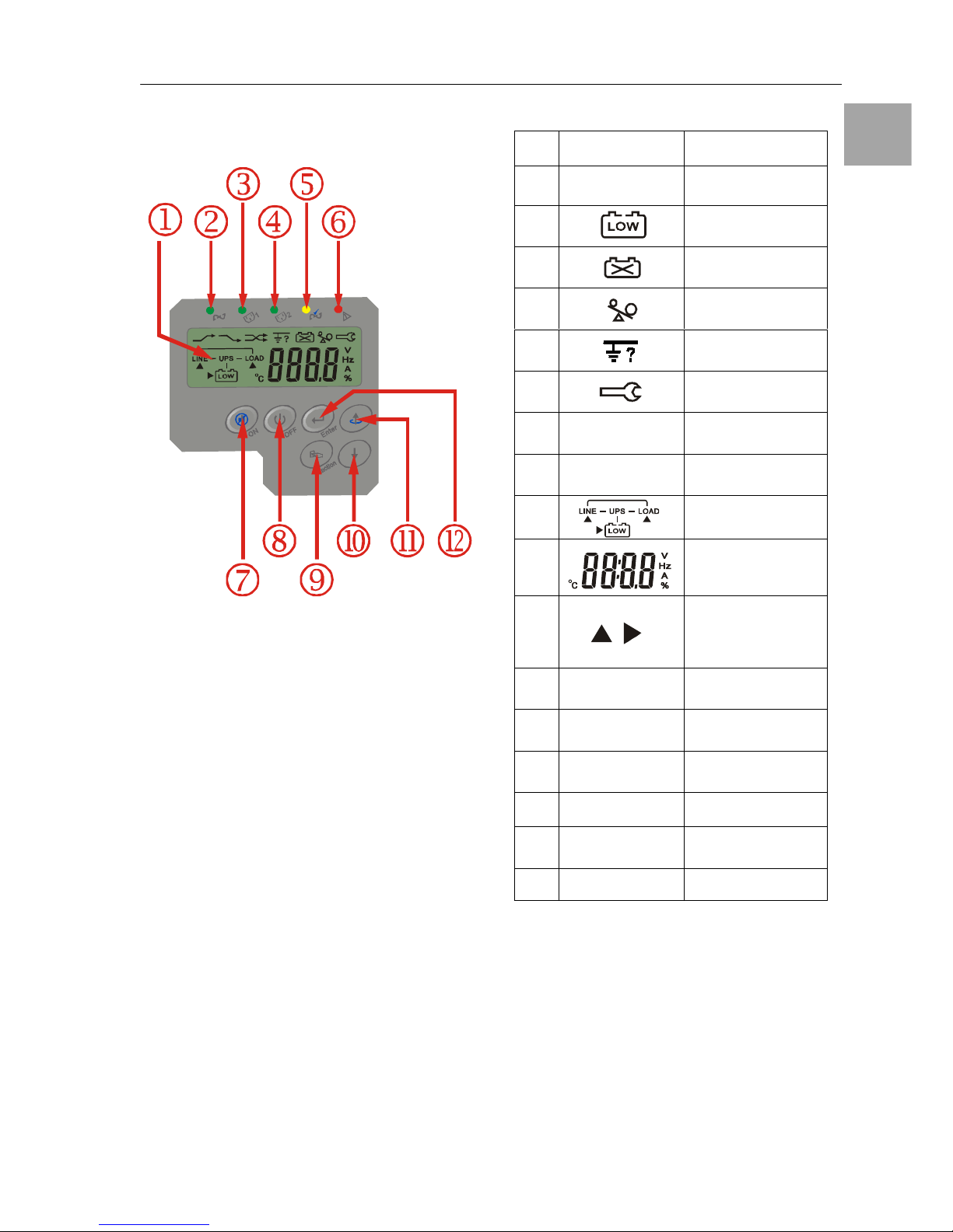
3.1. UPS Front Panel Display
①
LCD Display
②
Green LED steadily lights up to indicate that
the Utility input voltage is within the window
(160Vac~288Vac).
③, ④
Green LED lights up to indicate there is
an output available at the Programmable
Outlet 1 & Programmable Outlet 2.
⑤
Amber LED lights up to indicate the Bypass
Input is normal.
⑥
General Fault LED
⑦
UPS On/Alarm Silence
⑧
UPS OFF Switch
⑨
Special functions log in/out
⑩
Go to next page
⑪
Go to previous page or change the setting
of the UPS.
⑫
To re-confirm the change of UPS Setting
3.1.1. Symbols on the LCD Display Panel
Item Symbol Description
1
LINE
Utility or Bypass
Source
2 Battery Low
3 Battery Abnormal
4 UPS Overloading
5 Site Wiring Fault
6
UPS Working in
Service Mode
7
OFF
UPS Shutoff
8
FAIL
UPS Abnormal
Lock
9 UPS Flow Chart
10
4 Digits
Measurement
Display
11
Indicate the item
desired
to be measured
12
Er05
Battery Weak or
Dead
13
Er06
Output Short
Circuit
14
Er10
Inverter Overcurrent
15
Er11
UPS Overheat
16
Er12
UPS Output
Overloading
17
Er**
Other Error Code
UPS Functional Descriptions
UPS-Manual 8
EN
230V
1KVA
2KVA
3KVA
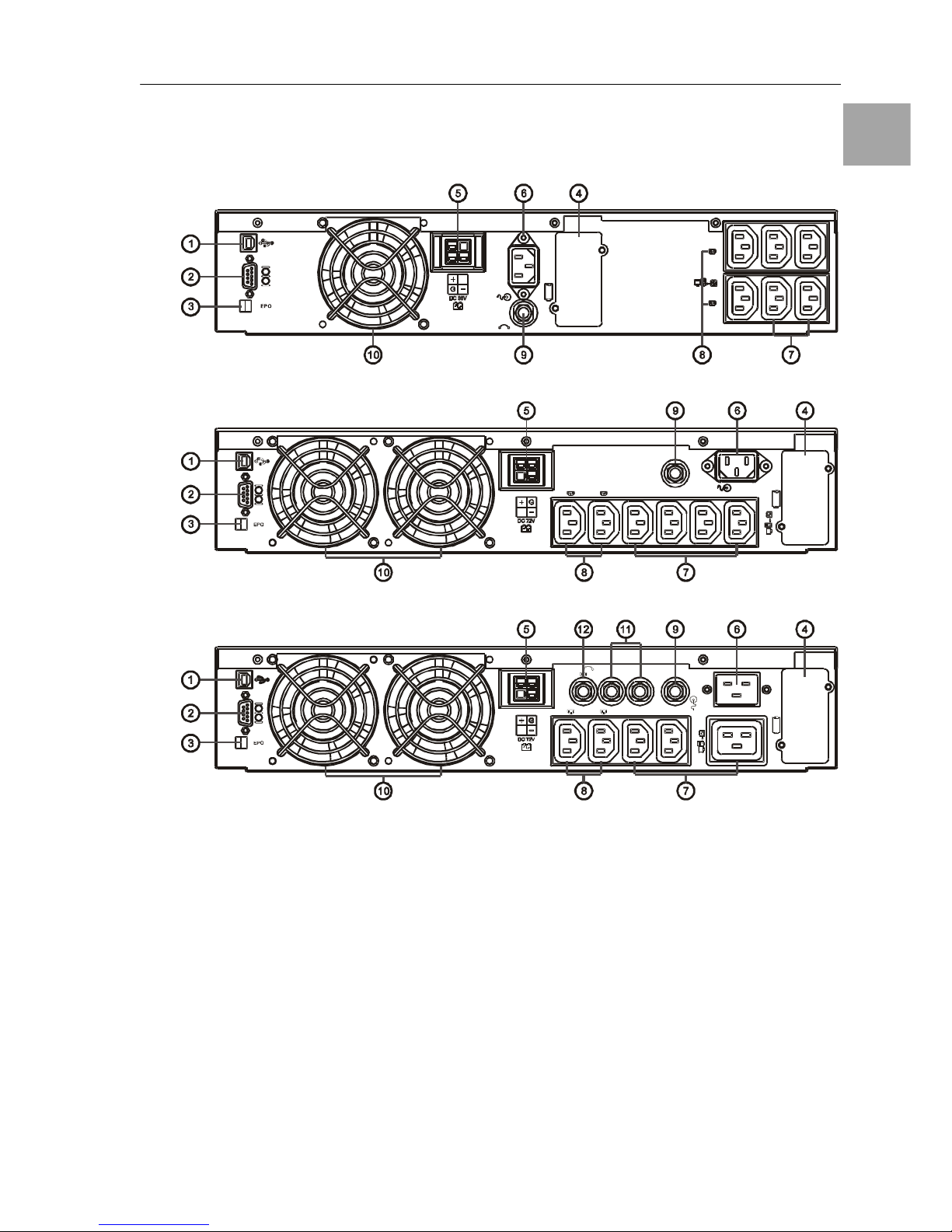
3.2. Rear Panel Descriptions
1. USB Port
2. RS232 Port
3. Emergency Power Off (EPO) Dry Contact
Signal inputs
4. Communication Card Options Slot
5. External Battery Connector
6. AC power connection socket
7. AC Outlets
8. Two programmable outlets
9. Utility Input fuse holder
10. Cooling Fans
11. Output fuse holders
12. Output fuse holders for two programmable
outlets
UPS Functional Descriptions
UPS-Manual 9
EN
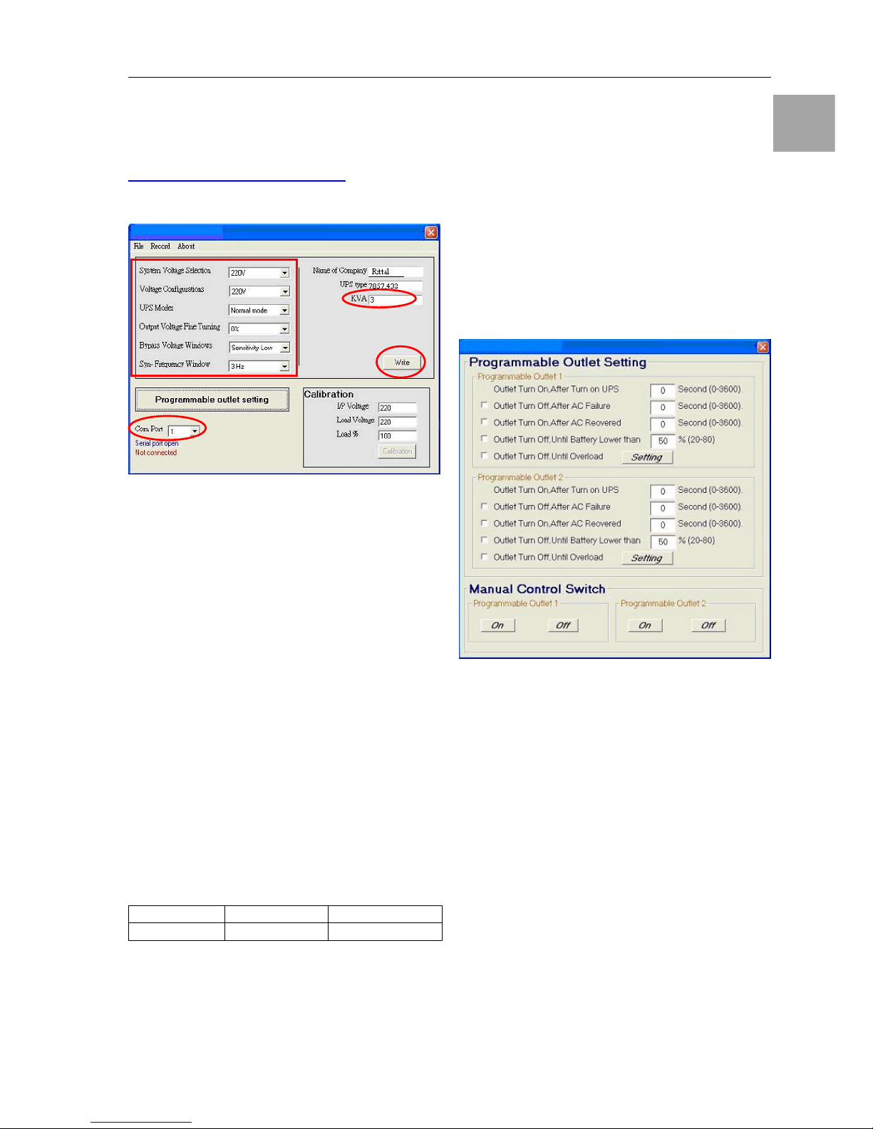
3.3. Operating Modes & Voltage System
Configurations
Download from
www.rimatrix5.com/dl_power.htm the “Setting
Tool” and open the Software to see the screen
as below:
3.3.1. System Configuration Settings
1. System Voltage Selection: Select Input
Voltage 220V
2. Voltage Configurations: Select UPS Output
Voltage 220V/230V/240V
3. UPS Modes: Select Normal/CF50*/CF60*
Mode
4. Output Voltage Fine Tuning : Output Voltage Regulation from 0 ~ ±3%
5. Bypass Voltage Windows: Sensitivity: Select Sensitivity Low/Sensitivity High**
6. Syn-Frequency Window: Select 3Hz/1Hz
Inverter Freq synchronizing range
7. kVA: Key in 1 or 2 or 3 for the UPS kVA
rating
8. Com Port: Select the Com Port of PC
9. Click on “Write” to confirm the configuration
settings. The UPS will beep twice to acknowledge setting is successful.
10. To override the new configurations, make
sure you will turn off the UPS first, then return on the UPS to get the new configurations working.
Sensitivity Low Sensitivity High
220V System 184V ~ 260V 194V ~ 260V
Note:
*CF50/CF60 = Frequency Converter mode 50
to 60Hz or vice versa
**Sensitivity Low : 184~260V,
High: 194~260V
3.3.2. Programmable Outlet Setting
The UPS is equipped with 2 programmable
outlets for use to supply to less critical loads.
These outlets can be disabled to shed the less
critical loads during back-up modes or overload
conditions to maintain quality power supply to
the more critical loads connected to the UPS.
Click on the “Programmable outlet setting” bar
to enter to the setting screen as shown below.
1. Outlet Turn On After Turn on UPS – select
the time to automatically enable this outlet
within the specified time when the UPS is
powered on. If “0” sec is selected, the outlet
will be enabled once the UPS is powered
on.
2. Outlet Turn Off After AC Failure – select
this option to automatically disable the outlet
within the specified time after utility outage
to shed the less critical loads to provide
longer battery back-up time for the other
more critical loads connected to the UPS.
3. Outlet Turn On After AC Recovered – select this option to automatically enable the
outlet within the specified time after the utility is restored.
 Loading...