

Page 1
AS 4050.454
Electrical crimping machine R8 E
Operating instructions
Page 2

Contents
EN
Contents
1 About this documentation .................................................. 4
2 General safety instructions ................................................. 5
2.1 Intended use .......................................................................................... 5
2.2 Not permitted ......................................................................................... 5
2.3 Machine dangers ................................................................................... 5
2.4 Operational hazards ............................................................................... 5
2.5 Hazard sources ...................................................................................... 5
2.6 Safety equipment ................................................................................... 5
2.7 Warning signs at and on the machine or components ............................ 6
2.8 Residual risks ......................................................................................... 6
2.9 Safety measures at the installation site ................................................... 6
2.10 Notes for the operating company ........................................................... 7
2.11 Personnel requirements ......................................................................... 7
2.11.1 Operator ........................................................................................................... 7
2.11.2 Technician ........................................................................................................ 7
2.12 Training and instruction .......................................................................... 7
2.13 Noise ..................................................................................................... 8
3 Device description .............................................................. 8
3.1 Overview ................................................................................................ 8
3.2 Technical data ........................................................................................ 9
4 Transporting the machine ................................................. 10
5 Setting up the machine .................................................... 10
5.1 Operating tools .................................................................................... 10
5.2 Machine connection ............................................................................. 10
5.3 Inserting the belt roll ............................................................................. 11
5.4 Cross-section setting ........................................................................... 12
5.4.1 Die size setting ............................................................................................... 13
5.4.2 Insulation stripping stage setting ..................................................................... 14
5.5 Replacing the belt roll ........................................................................... 14
5.6 Conductor insertion / conductor cutting ............................................... 14
6 Menu ............................................................................... 15
6.1 Jogging operation ................................................................................ 15
6.2 Counters .............................................................................................. 16
6.2.1 Reset daily quantity counter ............................................................................ 16
6.2.2 Service counter ............................................................................................... 16
6.3 Filling level monitoring .......................................................................... 16
6.4 Test menu ............................................................................................ 16
7 Maintaining the machine ................................................... 17
7.1 Authorised maintenance personnel ...................................................... 17
7.2 Maintenance notes ............................................................................... 17
7.3 Lubricant .............................................................................................. 17
7.4 Maintenance schedule ......................................................................... 18
7.4.1 Daily maintenance........................................................................................... 18
7.4.2 Monthly maintenance ...................................................................................... 18
7.4.3 6-monthly maintenance .................................................................................. 19
7.5 Replacing the insulation stripping blade ............................................... 21
7.6 Replacing ferrule separating blade ....................................................... 21
2 We reserve the right to make technical modifications. Rittal electrical crimping machine R8 E
8 Troubleshooting ............................................................... 23
8.1 Personnel for troubleshooting............................................................... 23
8.2 Machine does not start ........................................................................ 23
8.3 Ferrules placed too deep in the transport unit ...................................... 24
Page 3

Contents
8.4 Error messages .................................................................................... 24
8.5 Removing the wire end ferrule .............................................................. 25
EN
9 Machine decommissioning and disposal .......................... 25
9.1 Machine decommissioning ................................................................... 25
9.2 Machine disposal ................................................................................. 25
10 Electrical connection diagram .......................................... 26
11 Spare parts list and accessories ....................................... 27
Rittal electrical crimping machine R8 E We reserve the right to make technical modifications. 3
Page 4
1 About this documentation
Warning!
Caution!
Caution!
Symbol
Meaning
Warning: dangerous electrical voltage
Warning: injury to hands due to sharp blades
Work may only be performed by a qualified electrician
Only perform work with personal protective equipment
Disconnect the mains plug
Notes on documentation
EN
1 About this documentation
The warnings in this documentation are structured differently depending on the
severity of danger.
Possible risk of fatality!
Notices with the signal word "warning" warn you about situations
which could lead to fatal or serious injuries if you do not pay attention to the notices specified.
Risk of injury!
Notices with the signal word "caution" warn you about situations
which could lead to injury if you do not pay attention to the notices
specified.
Property damage!
Notices with the signal word "attention" warn you about dangers which
could result in damage to property.
Situation-related warnings may contain the following warning symbols:
Additional formatting is used in the rest of the text which has the following
meaning:
4 We reserve the right to make technical modifications. Rittal electrical crimping machine R8 E
Note:
This constitutes information which is not related to safety, but
which provides important information regarding correct and effective work.
Page 5

2 General safety instructions
This symbol indicates an "action point" and shows that you should perform
an operation or procedure.
– Bullet points are indicated with dashes.
2 General safety instructions
2.1 Intended use
The electrical crimping machine R8 E is an electrically-driven insulation stripping and crimping machine designed exclusively for insulation stripping from
flexible conductors in accordance with DIN 60228:2005 and the crimping of
"wire end ferrules on rolls" (0.5 – 2.5 mm²) on cable ends. For this reason, because of its construction, the machine has only this intended use.
For the intended use, the following must be observed:
– All notes from the operating instructions
– The documentation of the supplied products, as well as
– The notes for servicing/maintenance
Any other use is deemed improper.
The operational safety of the machine is guaranteed only for the intended use.
Only persons authorised by the manufacturer may perform changes, conversions and repairs to the machine.
Any safety-relevant changes or manipulations to the machine are prohibited. If
the operating company makes such changes or manipulations, safe operation
of the machines is not guaranteed.
The manufacturer accepts no liability for damage or consequential damages
that result because of the preceding measures.
Use only original spare parts and accessories authorised by the manufacturer.
The use of other parts voids the liability for any damage (also consequential
damages) that results from the use of other parts or non-authorised accessories.
EN
2.2 Not permitted
– Removing notification or warning signs.
– Opening the machine during operation.
– Using the machine with obvious defects or damage.
2.3 Machine dangers
A risk evaluation with subsequent safety inspection and safety acceptance was
performed on the electrical crimping machine R8 E. As for every machine,
some residual risks, that cannot be precluded because of design considerations, remain. See section 2.8 "Residual risks".
2.4 Operational hazards
The operator may rectify only those faults for which the housing does not need
to be removed.
2.5 Hazard sources
Before performing servicing, maintenance and cleaning work on the ma-
chine, switch off the machine, disconnect it from the power supply (e.g. cut
off the electricity supply, switch off the fuse).
2.6 Safety equipment
Safety equipment is installed to protect personnel. The operating company is
obliged to inspect the safety equipment annually.
Under no circumstances may safety devices be changed, removed or circumvented by changes to the machine.
Rittal electrical crimping machine R8 E We reserve the right to make technical modifications. 5
Page 6

2 General safety instructions
EN
Safety devices
Function
Inspection
Housing
The housing may be
closed again.
Inspect for damage.
Safety switch
The safety switch is acti-
is opened.
By a qualified electrician.
LPV-100-24 switched-
The SMPS protects
may be present.
By a qualified electrician.
Symbol
Meaning
The protective earth is a measure that in the event of a fault protects
earth" measure is provided by the protective conductor.
removed only by service
technicians or qualified
personnel. Only for
switched-off state of the
machine. After removal of
the housing, ensure that
the earthing wire is inserted before the machine is
vated when the front flap
mode power supply
(SMPS)
against dangerous voltages, because not more
than 60 VAC or 110 VDC
2.7 Warning signs at and on the machine or components
– PE conductor connection: This marking is placed on the earth screw.
against dangerous touch voltage and electrical shock. The "protective
The connection is made via an IEC connector with leading protective conductor contact. The "PE" protective conductor (green/yellow insulating sheath only
in Germany) is used for these protective measures.
2.8 Residual XXX risks
Even when all safety and warning notes are observed, residual risks remain for
the machine operation.
The machine is state-of-the-art and built according to recognised safety regulations. Nevertheless, hazards for users or third-parties can result when operating the machine.
– The machine may be used only for the intended purpose.
– The machine must be in proper safety condition during commissioning.
– Faults that can impair the safety must be rectified immediately, whereby the
manufacturer may need to be contacted.
– For opened flap, access to the fixed blade is possible and so cut injuries can
result.
– Manipulation of the safety devices can cause the reoccurrence of the de-
scribed hazards.
2.9 Safety measures at the installation site
The machine must be placed stable on a table.
– There is a large hazard risk should a machine fall.
6 We reserve the right to make technical modifications. Rittal electrical crimping machine R8 E
Page 7
2 General safety instructions
Note:
Target group
Operator
Technician
Transporting X X
Mounting X
Dismantling X
Setup
X
X
Operation X X
Cleaning X X
Maintenance X X
Repairs X
Inner-company instructions and checks should ensure that the
workplace and its vicinity remain clean and uncluttered.
2.10 Notes for the operating company
– The operating company is obliged to write operating instructions.
– The operating company is obliged to inspect the safety devices annually.
– Deploy only original fuses with the specified amperage.
– Knowledge of the local, operational safety and accident-prevention regula-
tions.
– All notes on machines must be kept legible, and renewed when necessary.
Notify the manufacturer without delay should defects become apparent, pro-
vided they were not caused intentionally.
Any imperfect machine parts must be replaced immediately.
2.11 Personnel requirements
The following target groups have different authorisations.
2.11.1 Operator
Requirements:
– Literacy skills
– Technical knowledge
– Instructed/trained
Knowledge:
– Machine function
– Intended use of the machine
– Machine safety devices
EN
2.11.2 Technician
Requirements:
– Rittal service technician
Work steps
2.12 Training and instruction
– Only trained and instructed personnel may work on the machine.
Rittal electrical crimping machine R8 E We reserve the right to make technical modifications. 7
Page 8

3 Device description
EN
1 2 3
4 5 6
7
8
9
– Repair work may be performed only by the manufacturer or authorised ser-
vice departments.
2.13 Noise
The A-weighted equivalent continuous sound pressure level of the R8 E crimping machine is ≤70 dB(A).
Consequently, ear muffs are not required for operating the machine.
3 Device description
3.1 Overview
Fig. 1: Front view
Fig. 2: Connection circuit-board
8 We reserve the right to make technical modifications. Rittal electrical crimping machine R8 E
Page 9

3 Device description
Electrical crimping machine R8 E
Conductor insertion length
40 mm
Wire end ferrules
0.5 – 2.5 mm²
Ferrule length
8 mm
Crimping form
Trapezoidal
Drive
Electric motor
Voltage
100…240 V
Frequency
50/60 Hz
Power consumption
100 VA
Fuse (mains filter module)
2 x T2AH250V
Degree of protection
IP 20
Protection class
I / PE conductor
Cycle time
1.8 s
Continuous sound pressure level
≤70 dB(A)
Dimensions (W x D x H)
288 mm x 349 mm x 230 mm
Weight
16 kg
Operating environment
Storage/transport temperature
-25 °C to +55 °C (short-term +70 °C)
Ambient temperature
+5 °C to 40 °C
Operating temperature
+10 °C to 45 °C
Max. operating altitude
2000 m above mean sea level
Humidity
50% at 40 °C (without dewing)
90% at 20 °C (without dewing)
Contamination level
2
Key
1 Belt roll
2 Roll holder
3 Flap
4 Touch display
5 Insertion funnel
6 Twist lock
7 ON/OFF power switch
8 Fuses
9 Mains plug
3.2 Technical data
EN
Rittal electrical crimping machine R8 E We reserve the right to make technical modifications. 9
Page 10

4 Transporting the machine
Note:
Caution!
Caution!
Tools
Included in the scope of supply
Allen key size 4
✔
Allen key size 2.5
✘
Tweezers
✘
Caution!
EN
4 Transporting the machine
Always use the complete original packaging for transport.
The machine with all its accessories must be sent for service and
repair work.
Force can cause damage to the machine.
Transport the machine properly.
There is a risk of injury, in particular to feet, should the machine
fall.
Wear safety shoes when transporting the machine.
5 Setting up the machine
Read the operating instructions carefully before commissioning the machine.
Deploy the machine only in a dry environment.
5.1 Operating tools
5.2 Machine connection
The electrical data shown on the rating plate must match that of the power
grid.
– Otherwise, damage can occur to the machine.
Connect the mains cable to the mains plug (see fig. 3, item 3) of the machine
and to the power supply.
Switch on the electrical crimping machine R8 E at the power switch (see
fig. 3, item 1).
10 We reserve the right to make technical modifications. Rittal electrical crimping machine R8 E
Page 11

5 Setting up the machine
1 2 1 2 3
Fig. 3: Connection plate
Key
1 ON/OFF power switch
2 Fuses (2 x T2AH250V)
3 Mains plug
EN
5.3 Inserting the belt roll
Place the belt roll (see fig. 4, item 1) so that clockwise unrolling is possible.
Open the twist lock (see fig. 4, item 2) and swivel the flap to the side.
The transport pin must be at the bottom!
Fig. 4: Inserting the belt roll
Push the wire end ferrule belt into the magazine until the lowermost ferrule
latches.
But not further, because otherwise a malfunction can occur.
Check this by applying slight tension to the belt.
Rittal electrical crimping machine R8 E We reserve the right to make technical modifications. 11
Page 12

5 Setting up the machine
EN
2
1
3 5
4
Fig. 5: Feeding in the wire end ferrules
Close the flap via the twist lock.
Roll up the loose wire end ferrule belt.
Fig. 6: End position
5.4 Cross-section setting
Fig. 7: "Display" menu display
Key
1 Die size
2 Insulation stripping stage
3 Conductor cross-section
4 Day quantity counter
5 Initial position symbol
12 We reserve the right to make technical modifications. Rittal electrical crimping machine R8 E
Page 13

5 Setting up the machine
Cross-section [mm²]
Die size
Insulation stripping stage
0.50
1, 2, 3
0.75
4, 5, 6
1.00
7, 8, 9
1.50
10, 11, 12
2.50
III
13, 14, 15
Blade replacement
I II III
99
Caution!
3
2
1
I
II
Tab. 1: Setting values
5.4.1 Die size setting
Open the twist lock.
Swivel the flap to the side.
There is risk of finger injuries by the fixed ferrule separating blade.
Do not touch the blade when the drum is turned.
Press the drum backwards (see fig. 8, item 1) and turn (see fig. 8, item 2) to
the desired die size.
Release the drum until it latches.
The current nest is displayed with the bars (see fig. 8, item 3).
Check by turning whether the drum has latched.
EN
Rittal electrical crimping machine R8 E We reserve the right to make technical modifications. 13
Fig. 8: Setting the die size
Page 14

5 Setting up the machine
EN
Note:
40 mm
Correct
Incorrect
Correct
Inclined
1 2
5.4.2 Insulation stripping stage setting
Required tool:
– Allen key size 4
The insulation stripping stage / conductor cross-section is shown in the touch
display.
Turning clockwise increases the cross-section.
–
+
Fig. 9: Insulation stripping stage setting
5.5 Replacing the belt roll
Open the twist lock.
Swivel the flap to the side.
Press the transport pin upwards completely (see fig. 10, item 1) and remove
the wire end ferrule belt (see fig. 10, item 2) from the magazine.
Continue in accordance with section 5.3 "Inserting the belt roll".
Fig. 10: Replacing the belt roll
5.6 Conductor insertion / conductor cutting
– The cable must be cut straight and must not have any kinks or
bends.
– Push the cable through the insertion funnel into the contact.
14 We reserve the right to make technical modifications. Rittal electrical crimping machine R8 E
cut
Page 15

6 Menu
Protected
Removed
Crushed
Recessed
Jogging operation display
"Initial position"
Jogging operation display
"Not in initial position"
Incorrect
Tab. 2: Wire entry
6 Menu
6.1 Jogging operation
conductor
conductor
conductor
conductor
EN
3
1
Fig. 11: Jogging operation
2
– Machine at initial position / switched on.
– One of the insulation stripping stages 1 to 15 must be set.
Switch off the machine.
Open the flap.
Remove the belt.
Close the flap.
Keep the display pressed.
Switch on the machine (machine in jogging operation).
The display switches to the "Jogging operation initial position" display.
Traverse backwards (see fig. 11, item 1) or forwards (see fig. 11, item 2) in
jogging operation using the arrow keys.
Traverse the machine manually until the initial position (see fig. 11, item 3) is
reached again.
Alternatively: Press the hand symbol for 3 seconds.
This causes the machine to travel automatically to the initial position.
Switch off the machine.
Insert the belt roll.
Switch on the machine.
Rittal electrical crimping machine R8 E We reserve the right to make technical modifications. 15
Page 16

6 Menu
EN
Touch display
3
x
6.2 Counters
1
2
3
Fig. 12: Counters
Key
1 Total counter
2 Day counter
3 Service counter
4 Menu number
5 Filling level monitoring status: x = active; 0 = inactive
4 5
6.2.1 Reset daily quantity counter
– Machine at initial position / switched on.
Press the display for 3 seconds.
Press the display for 5 seconds.
Confirm the display briefly.
6.2.2 Service counter
When the quantity (200,000 items) in the "Service" field is attained, "Service"
flashes when switched on next time.
Press the touch display once to acknowledge the display.
This indicates that the next service is now due and the machine should be sent
to the manufacturer.
6.3 Filling level monitoring
The filling level monitoring checks whether the start switch has been pressed
sufficiently long. This function is active as standard.
Deactivate/activate the function
Set insulation stripping stage 99.
Press the touch display for 3 seconds.
The current status of the filling level monitoring is displayed:
X = On, O = Off.
Tap the touch display briefly to change the status.
Press the touch display for 3 seconds.
The display switches to the "Test inputs" menu.
Press the touch display for 3 seconds.
The display switches to the production menu.
Set the desired insulation stripping stage (see section 5.4.2 "Insulation strip-
ping stage setting").
6.4 Test menu
Status display of the inputs (0 or 1).
Set insulation stripping stage 6.
Switch the machine on and off again.
Tap the touch display ten times quickly.
The menu is exited when the touch display is pressed for at least 2 seconds.
16 We reserve the right to make technical modifications. Rittal electrical crimping machine R8 E
Page 17

7 Maintaining the machine
Warning!
Note:
EN
1
4
2
3
Fig. 13: Counters
Key
1 Start: Microswitch
2 Drum position
3 Drum position
4 Drum position
5 Stop: Light barrier
6 Flap
7 Maintaining the machine
Electrical shock caused by working on live components!
Before working on the machine, it must be discon-
nected from the power grid.
5
6
7.1 Authorised maintenance personnel
Maintenance work may be performed only by specially trained and instructed
personnel.
7.2 Maintenance notes
– Never clean the machine interior with compressed air.
– Do not use spray oil or spray grease.
– If possible, use silicone or PTFE oils (Teflon oil), e.g. Divinol GWA
ISO 46.
– Use lubricating greases suitable for roller bearings and sliding
surfaces.
– The display and the touch screen are made of plastic and must
not come into contact with hard objects. The touch-screen surface can be cleaned with a soft cloth without any solvents.
7.3 Lubricant
Lubricating grease
– Recommended grease: BP Energrease PR-EP 00
Rittal electrical crimping machine R8 E We reserve the right to make technical modifications. 17
Page 18

7 Maintaining the machine
EN
Component
Activity
Machine
Empty the refuse drawer.
Lubricating oil
– Recommended oil: WD-40 Classic
7.4 Maintenance schedule
7.4.1 Daily maintenance
Emptying the refuse drawer
Observe the insertion position of the refuse drawer.
Fig. 14: Refuse drawer
7.4.2 Monthly maintenance
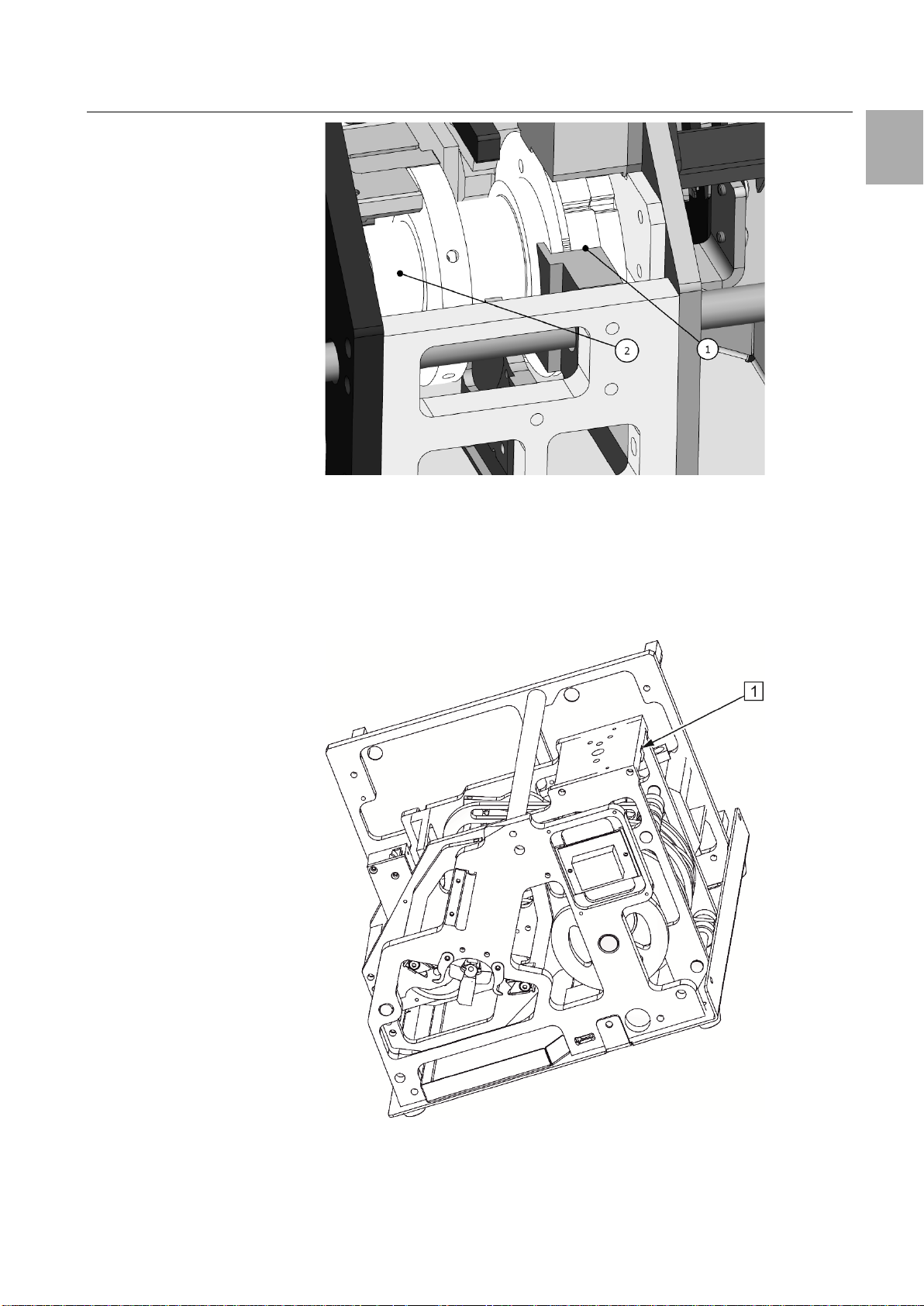
Open the flap.
Oil the support (see fig. 15, item 1) and bearing assembly (see fig. 15, item 2)
of the crimping drum.
18 We reserve the right to make technical modifications. Rittal electrical crimping machine R8 E
Page 19
7 Maintaining the machine
Fig. 15: Oiling the crimping drum
7.4.3 6-monthly maintenance
Dismantle the housing.
Oil the gap between the setting wheel and the insulation stripping stage.
To do this, place the machine at 45°.
Allow lubricating oil to flow into the gap (see fig. 16, item 1) between the set-
ting wheel and the cover.
EN
Fig. 16: Oiling insulation stripping stage setting
Rittal electrical crimping machine R8 E We reserve the right to make technical modifications. 19
Page 20

7 Maintaining the machine
EN
Component
Activity
Shafts
Grease all marked shafts and guides
Component
Activity
Cams
Apply the above-mentioned grease
of the machine.
Fig. 17: Shafts
with a brush to the grooves for all
marked components.
Fig. 18: Side view, right
20 We reserve the right to make technical modifications. Rittal electrical crimping machine R8 E
Page 21

7 Maintaining the machine
Warning!
Caution!
Caution!
7.5 Replacing the insulation stripping blade
Electrical shock caused by working on live components!
Before working on the machine, it must be discon-
nected from the power grid.
There is risk of finger injuries at the insulation stripping blades.
Never touch the blade.
Set insulation stripping stage 99.
Switch off the machine.
Open the flap and remove the belt.
Close the flap.
Press the display and switch on the machine.
The machine travels to the blade replacement position, see display.
Switch off the machine.
Open the flap.
Remove the screws (see fig. 19, item 1).
Replace the insulation stripping blade (see fig. 19, item 2).
Insert the insulation stripping blade in the blade holder until the limit stop.
Close the flap.
Switch on the machine, see display.
Press the display for 3 seconds.
The machine travels automatically to the initial position.
Select the insulation stripping stage.
Switch off the machine.
Insert the wire end ferrule belt.
EN
Fig. 19: Replacing the insulation stripping blade
7.6 Replacing ferrule separating blade
There is risk of finger injuries at the ferrule separating blade.
Never touch the blade.
Switch off the machine.
Rittal electrical crimping machine R8 E We reserve the right to make technical modifications. 21
Page 22
7 Maintaining the machine
EN
Open the flap.
Press the transport pin upwards.
Remove the belt.
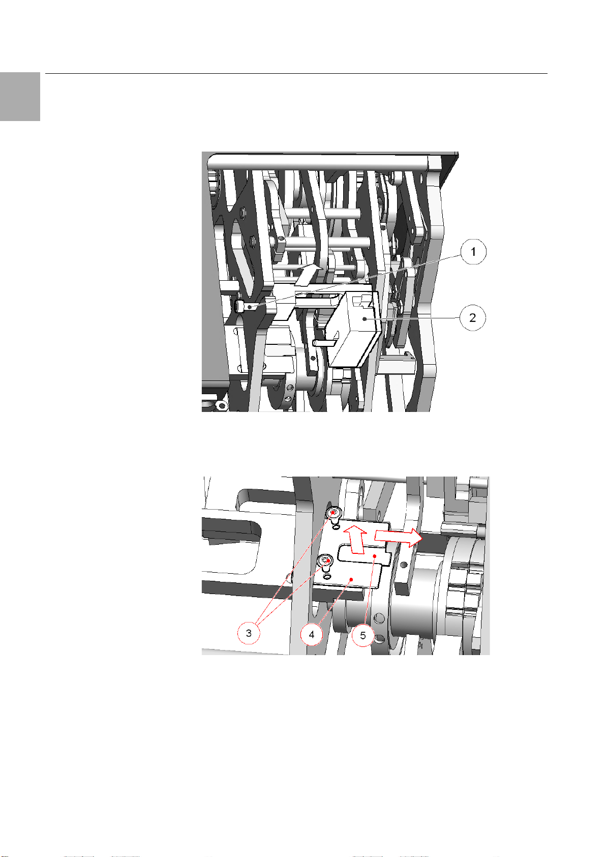
Loosen the screw with an Allen key size 4 (see fig. 20, item 1).
Remove the magazine at the top (see fig. 20, item 2).
Fig. 20: Magazine
Remove the two screws with an Allen key size 2.5 (see fig. 21, item 3).
Remove the separating blade cover (see fig. 21, item 4).
Replace the ferrule separating blade (see fig. 21, item 5).
Fig. 21: Replacing the ferrule separating blade
The installation is performed in the reverse order.
Observe the installation position of the ferrule separating blade.
22 We reserve the right to make technical modifications. Rittal electrical crimping machine R8 E
Page 23

8 Troubleshooting
Warning!
Cause
Correction
The power supply is interrupted.
Check the mains cable and the fuses.
Fig. 22: Ferrule separating blade installation position
Install the magazine.
EN
–
Fig. 23: Installing the magazine
Ensure that the upper edge is flush!
8 Troubleshooting
Electrical shock caused by working on live components!
Before working on the machine, it must be discon-
nected from the power grid.
8.1 Personnel for troubleshooting
Faults may the rectified only by trained personnel (fitters) and qualified electricians.
8.2 Machine does not start
Rittal electrical crimping machine R8 E We reserve the right to make technical modifications. 23
Page 24
8 Troubleshooting
EN
Cause
Correction
Filling level monitoring active and start
Acknowledge the fault: Press touch
Cause
Correction
The blade cuts in the wire end ferrule:
Switch off the machine.
Display on touch
display
Cause
Correction
The flap is open.
Close the flap.
Ferrule not removed after
Remove the ferrule (see sec-
Triggering mechanism
chine does not start).
Press the touch display once
Triggering mechanism
Press the touch display once
Stop switch fault
Press the touch display once
Start switch fault
Check the start switch for
Conductor introduced too
early
Introduce conductor later.
Motor fault
Press the touch display once
Service message
Service
switch pressed too briefly.
display.
Introduce the conductor correctly.
8.3 Ferrules placed too deep in the transport unit
Current too high, machine switches off.
Start the machine in jogging operation
(see section 6.1 "Jogging operation").
Travel forwards or backwards.
Remove the belt.
Inspect for further damage.
8.4 Error messages
work cycle.
tion 8.5 "Removing the wire
end ferrule").
pressed too briefly (ma-
pressed too briefly (machine starts).
– The stop switch does
not switch.
– The stop switch is still
pressed.
– Start switch not free.
– The motor does not run
or jams (current too
high).
briefly.
briefly.
Check the crimp quality.
briefly.
blockage.
Press the touch display once
briefly.
briefly.
24 We reserve the right to make technical modifications. Rittal electrical crimping machine R8 E
– Service quantity at-
tained.
Deleted there.
Page 25
9 Machine decommissioning and disposal
Display on touch
display
Cause
Correction
Drum position incorrect or
The drum must be at the correct
Setting error
Press the touch display once
Machine not at the initial
Travel in jogging operation to
Note:
Machine disposal as house refuse is not permitted.
Note:
EN
does not match the insulation stripping stage.
position.
– Jogging operation
– The insulation stripping
stage and the die size
briefly.
do not match.
position.
If there are further faults, contact the manufacturer.
initial position.
8.5 Removing the wire end ferrule
Open the front flap (see fig. 1, item 3).
Search for missing wire end ferrule.
If required, remove the transport unit (see section 7.6 "Replacing ferrule sep-
arating blade").
Remove the wire end ferrule.
If required, reinstall the transport unit.
Close the front flap.
Tap the touch display briefly.
9 Machine decommissioning and disposal
9.1 Machine decommissioning
Switch off the machine.
Withdraw the mains plug.
Pack the machine in the original packaging.
The machine is now prepared for transport and disposal, if necessary.
9.2 Machine disposal
Decommission the machine as described in section 9.1 "Machine decom-
missioning".
Ensure the machine disposal in accordance with the national and local regu-
lations.
The machine should be disposed of environmentally conform
and properly.
You can send the product to Rittal for disposal. Contact your
responsible country representative.
Rittal electrical crimping machine R8 E We reserve the right to make technical modifications. 25
Page 26

10 Electrical connection diagram
EN
10 Electrical connection diagram
26 We reserve the right to make technical modifications. Rittal electrical crimping machine R8 E
Page 27

11 Spare parts list and accessories
No.
Designation
Model no.
2
AS wire end ferrules belt 0.5 mm² 8 mm long
4050.746
3
AS wire end ferrules belt 0.75 mm² 8 mm long
4050.747
4
AS wire end ferrules belt 1.00 mm² 8 mm long
4050.748
3
AS wire end ferrules belt 1.5 mm² 8 mm long
4050.749
3
AS wire end ferrules belt 2.5 mm² 8 mm long
4050.750
Note:
11 Spare parts list and accessories
In the event of an order, specify the serial number of the ma-
chine.
EN
Rittal electrical crimping machine R8 E We reserve the right to make technical modifications. 27
Page 28

You can find the contact details of all
Rittal companies throughout the world here.
www.rittal.com/contact
RITTAL GmbH & Co. KG
Postfach 1662 · D
Phone +49(0)2772 505
E
10.2018 / D-0100-00000026 Rev. 0
◾
◾
◾
◾
◾
Enclosures
Power Distribution
Climate Control
IT Infrastructure
Software & Services
-mail: info@rittal.de · www.rittal.com
-35726 Herborn
-0 · Fax +49(0)2772 505-2319
 Loading...