

Page 1
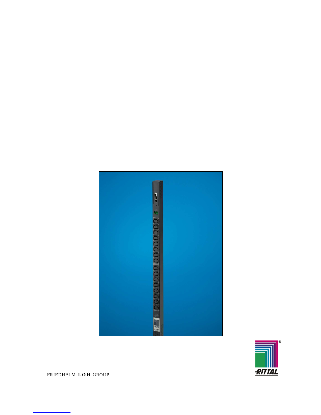
EN Switched Power Distribution Unit
DK 7856.530 / 540 / 550
Assembly, Installation and Operation
A40195 01 IT 74
Page 2

2
Switched Power Distribution Unit
Microsoft Windows is a registered trademark of Microsoft Corporation.
Acrobat Reader is a registered trademark of Adobe Systems Incorporated.
Page 3

Table of Contents 1
Switched Power Distribution Unit
3
EN
1 Table of Contents
1 Table of Contents ..............................3
2 Documentation Notes .......................4
3 Safety Instructions ............................4
3.1
Safety Precautions.......................... 5
3.2
Life-Support Policy.......................... 6
4 Product Introduction.........................7
4.1
Technical Equipment....................... 7
4.2
Power Supply.................................. 8
4.3
Usable Sensors............................... 8
4.4
Accessories..................................... 8
4.5
Optional Accessories ...................... 8
5
Mounting ............................................9
5.1
Mounting the PDU........................... 9
5.2
Expansion Module........................... 9
6 Installing...........................................10
6.1
Security advices............................ 10
6.2
Connecting to the Power Source .. 10
6.3
Connecting Devices...................... 10
6.4
Connecting to the Unit ..................10
7 Operations........................................11
7.1
Interfaces ...................................... 11
7.1.1 Outlet Naming and Grouping ........ 11
7.1.2 Usernames and Passwords.......... 11
7.2
HTML Interface ............................. 12
7.2.1 Logging In ..................................... 13
7.2.2 Power Monitoring .......................... 13
7.2.3 Environmental Monitoring ............. 14
7.2.4 Configuration................................. 14
7.2.5 Tools ............................................. 24
7.3
Command Line Interface............... 24
7.3.1 Administration Commands............ 31
7.3.2 System Administration .................. 39
8 Advanced Operations .....................49
8.1
SSL ............................................... 49
8.1.1 Setting up SSL Support ................49
8.2
SSH............................................... 49
8.3
SNMP/Thresholds......................... 50
8.4
LDAP............................................. 56
8.4.1 Configuring LDAP Groups ............61
8.4.2 LDAP Technical Specifications..... 64
8.4.3 LDAPS Client Specifications......... 65
8.5
TACACS+...................................... 65
8.5.1 TACACS+ Privilege Levels ........... 67
8.6
Logging ......................................... 69
8.6.1 Email..............................................70
8.7
Upload/Download...........................72
9 Appendices...................................... 73
9.1
Resetting to Factory Defaults ........73
9.2
Uploading Firmware.......................74
10 Technical Specifications ................ 74
10.1 Technical Data...............................74
10.2 Data Connections ..........................75
10.3 LED Indicators ...............................75
10.4 Regulatory Compliance..................76
11 Maintenance and Cleaning............. 77
11.1 Cleaning.........................................77
12 Customer Service ........................... 77
Page 4
Documentation Notes 2
4
Switched Power Distribution Unit
EN
2 Documentation Notes
The audience for this guide is the technical specialist familiar with the assembly, installation and
operation of the Switched PDU System.
You should read this operating guide prior to
commissioning and store the guide so it is readily
accessible for subsequent use.
Rittal cannot accept any liability for damage and
operational malfunctions that result from the nonobservance of this guide.
Retention of Documents
This guide and all associated documents are part
of the product. They must be given to the operator
of the unit and must be stored so they are available when needed.
Symbols Used
The following safety and other notes are used in
this guide:
Symbol for handling instructions:
•
This bullet point indicates that you should
perform an action.
Safety and other notes:
Danger!
Immediate danger to health and life!
Warning!
Possible danger for the product and
the environment!
Note!
Useful information and special features.
3 Safety Instructions
1. Assembly and installation of the Switched
PDU, in particular for wiring the enclosures
with mains power, may be performed only
by a trained electrician. Other tasks associated with the PDU, such as the assembly
and installation of system components with
tested standard connectors, and the operation and configuration of the PDU may be
performed only by instructed personnel.
2. Do not open the case, as there are no serviceable parts inside. Your warranty will be
void.
3. Do not try to repair the unit yourself; contact
your local supplier or your warranty will be
void.
4. If liquids are spilt onto the PDU or foreign
objects dropped into the unit, the warranty
will be null and void.
5. Do not install the PDU in an environment
with sparks, smoke or gas.
6. The PDU is designed to be installed and
commissioned in a sheltered, controlled environment as follows:
- Operating temperature 0-40°C and 5-
90% non-condensing humidity.
- Always avoid contact with direct
sunlight.
- Do not install the PDU in inflammable
or hazardous environment.
- Dusty, corrosive and salty envi-
ronments can do damage to the PDU.
- Install the PDU indoors as it is not de-
signed for installation outdoors.
7. Install the PDU away from objects that give
off excessive heat and areas that are excessively wet.
8. Always switch off the PDU when relocating
it.
9. Make sure that the AC main supply outlet is
correctly grounded.
10. Please ensure that the input voltage of the
PDU matches the utility supply voltage.
11. Observe the valid regulations for the electrical installation for the country in which the
unit is installed and operated, and the national regulations for accident prevention.
Also observe any company-internal regulations (work, operating and safety regulations).
Use only genuine or recommended parts and
accessories. The use of other parts can void the
liability for any resulting consequences.
Page 5
Safety Instructions 3
Switched Power Distribution Unit
5
EN
3.1 Safety Precautions
This section contains important safety and regulatory information that should be reviewed before installing
and using the Switched Power Distribution Unit.
Only for installation and use
in a Restricted Access Location in accordance with the
following installation and use
instructions.
Seulement pour l’installation et
l’utilisation dans une Zone Interdite conformément aux installations et l’utilisation des
indications suivantes.
Nur zur Installation und Verwendung in einem Sicherheitsbereich gemäß den folgenden
Installations- und Verwendungsanleitungen.
This equipment is designed
to be installed on a dedicated
circuit.
Cet équipement est conçu à
être installé sur un circuit spécialisé.
Diese Ausrüstung ist zur Installation in einem festen Stromkreis vorgesehen.
Dedicated circuit must have
circuit breaker or fuse protection.
PDUs have been designed
without a master circuit
breaker or fuse to avoid becoming a single point of failure. It is the customer’s responsibility to provide adequate protection for the dedicated power circuit. Protection of capacity equal to the
current rating of the PDU
must be provided and must
meet all applicable codes and
regulations. In North America, protection must have a
10,000A interrupt capacity.
Le circuit spécialisé doit avoir
un disjoncteur ou une protection de fusible. PDUs ont été
conçus sans disjoncteur général ni fusible pour éviter que
cela devient un seul endroit de
panne. C’est la responsabilité
du client de fournir une protection adéquate pour le circuitalimentation spécialisé. Protection de capacité équivalant à la
puissance de l'équipement, et
respectant tous les codes et
normes applicables. Les disjoncteurs ou fusibles destinés à
l'installation en Amérique du
Nord doivent avoir une capacité d'interruption de 10.000 A.
Der feste Stromkreis muss mit
einem Schutzschalter oder
einem Sicherungsschutz versehen sein.
PDUs verfügt über keinen
Hauptschutzschalter bzw. über
keine Sicherung, damit kein
einzelner Fehlerpunkt entstehen kann. Der Kunde ist dafür
verantwortlich, den Stromkreis
sachgemäß zu schützen. Der
Kapazitätsschutz entspricht der
aktuellen Stromstärke der Geräte und muss alle relevanten
Codes und Bestimmungen
erfüllen. Für Installation in
Nordamerika müssen Ausschalter bzw. Sicherung über
10.000 A Unterbrechungskapazität verfügen.
The plug on the power supply
cord shall be installed near
the equipment and shall be
easily accessible.
La prise sur le cordon
d’alimentation sera installée
près de l’équipement et sera
facilement disponible.
Der Stecker des Netzkabels
muss in der Nähe der Ausrüstung installiert werden und
leicht zugänglich sein.
Installation Orientation:
PDUs are design to be installed in vertical orientation.
Installation Orientation : PDUs
sont conçues pour être installées dans une orientation verticale.
Installationsausrichtung: PDUs
sind zur vertikalen Installation
vorgesehen.
Always disconnect the power
supply cord before opening to
avoid electrical shock.
Toujours déconnecter le cordon d’alimentation avant
d’ouvrir pour éviter un choque
électrique.
Ziehen Sie vor dem Öffnen
immer das Netzkabel heraus,
um die Gefahr eines elektrischen Schlags zu vermeiden.
WARNING! High leakage
current! Earth connection is
essential before connecting
supply!
ATTENTION ! Haut fuite très
possible ! Une connection de
masse est essentielle avant de
connecter l’alimentation !
ACHTUNG! Hoher Ableitstrom!
Ein Erdungsanschluss ist vor
dem Einschalten der Stromzufuhr erforderlich!
WARNING!
Double Pole/Neutral Fusing
ATTENTION!
Double Pôle/Fusible sur le
Neutre
ACHTUNG!:
Zweipolige bzw. Neutralleiter-
Sicherung
Page 6

Safety Instructions 3
6
Switched Power Distribution Unit
EN
3.2 Life-Support Policy
As a general policy, Rittal does not recommend
the use of any of its products in the following situations:
• life-support applications where failure or
malfunction of the Rittal product can be reasonably expected to cause failure of the lifesupport device or to significantly affect its
safety or effectiveness.
• direct patient care.
Rittal will not knowingly sell its products for use in
such applications unless it receives in writing assurances satisfactory to Rittal that:
• the risks of injury or damage have been
minimized,
• the customer assumes all such risks, and
• the liability of Rittal is adequately protected
under the circumstances.
The term life-support device includes but is not
limited to neonatal oxygen analyzers, nerve
stimulators (whether used for anaesthesia, pain
relief or other purposes), auto-transfusion devices, blood pumps, defibrillators, arrhythmia
detectors and alarms, pacemakers, haemodialysis systems, peritoneal dialysis systems, neonatal
ventilator incubators, ventilators (for adults or
infants), anaesthesia ventilators, infusion pumps,
and any other devices designated as “critical” by
the U.S. FDA.
Page 7
Product Introduction 4
Switched Power Distribution Unit
7
EN
4 Product Introduction
The Switched Power Distributing Unit (Switched
PDU) is a compact Distribution Unit, which can be
mounted easy and quick into every server rack. It
featured several C13 Plugs and has a voltage
and current measurement module.
By using the Web-Interface you can configure and
switch every single plug in the cabinet.
If one or more values of the Unit crosses the determined thresholds level you decided, the information can be send via SNMP or email to several
positions, which you can describe.
4.1 Technical Equipment
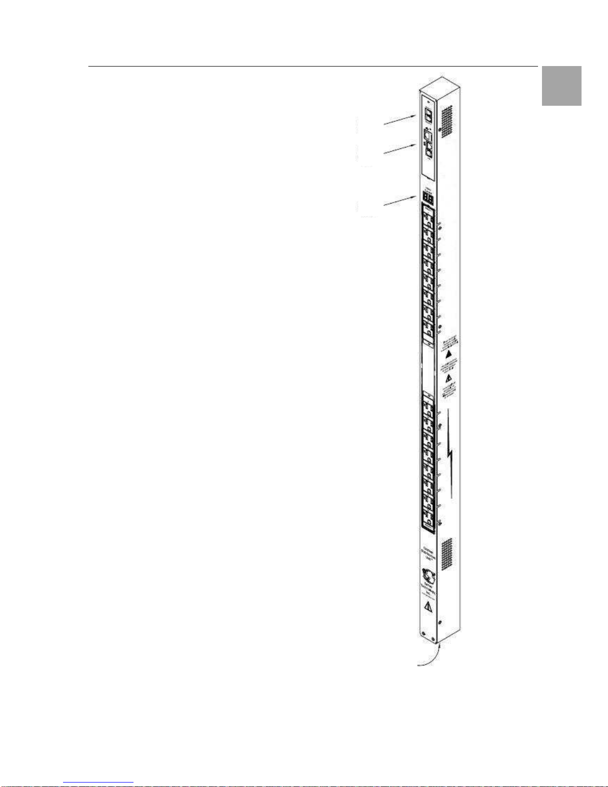
Figure 1 shows the technical equipment of the
Switched PDU.
1. Power inlet/cord
2. LED displays the current load for each infeed
3. RJ45 connectors for Serial (RS-232) and
Ethernet connection
4. Mini RJ-12 connectors for sensors
A number is printed above each outlet. These
numbers may be used in commands that require
an outlet name.
Abb. 1 Technical Equipment of the PDU
4
3
2
1
Page 8

Product Introduction 4
8
Switched Power Distribution Unit
EN
4.2 Power Supply
The Switched PDU is powered with the included
Connection Plug. The used Voltage depends of
the model, which is used.
DK-Nr.
Plug Power Supply
7856.530 1-phase
230V / 50 – 60 Hz
7856.540 3-phase 400V / 50 – 60 Hz
7856.550 2 x 1-phase 230V / 50 – 60 Hz
Tab. 1 Power Supply
4.3 Usable Sensors
The Switched PDU has two Mini RJ-11 T/H-Ports,
which can be used for several Sensors.
Connect the mini RJ-11 Plug from the sensor to
the T/H-Port on the PDU.
4.4 Accessories
Before installing your Switched PDU, refer to the
following lists to ensure that you have all the
items shipped with the unit as well as all other
items required for proper installation.
• Look for obvious damages on the package
Value Name
1 Switched PDU
1
Connection Cable 3 m (1-phase / 3phase, depends on model)
1
RJ45-/RJ45 - Cross cable
1
RJ45-/DB9F-Adapter for serial interface
1
RJ12-/RJ12 - Cross cable
1
Clips for Outputs
1 Mounting material
1 Instruction Manual
Tab. 2
Materials provided
4.5 Optional Accessories
Depending on the application it can be necessary
to order some optional accessories. Rittal offers
the following accessories for the Switched PDU:
Accessories Name Devices DK - Nr.
Expansion
Module
Slave Module - On request
C13/C14
0,5 m
2 7856.014
Server con-
nection plug
extension
cord
1,5 m
1 7200.215
Tab. 3 Optional Accessories
Page 9
Mounting 5
Switched Power Distribution Unit
9
EN
5 Mounting
The included installation set allows the mounting
of the unit on the cabinet frame and in 800 mm
Cabinets also on the side of the 19-inch level.
Mounting hardware:
• Two removable flanges with four M4 screws
• Two mounting L-brackets with nut plates, four
sets of screws and washers
• Optional button mounts
Required Items:
• Flathead and Phillips screwdrivers
• Screws, washers and nuts to attach the PDU to
your rack
5.1 Mounting the PDU
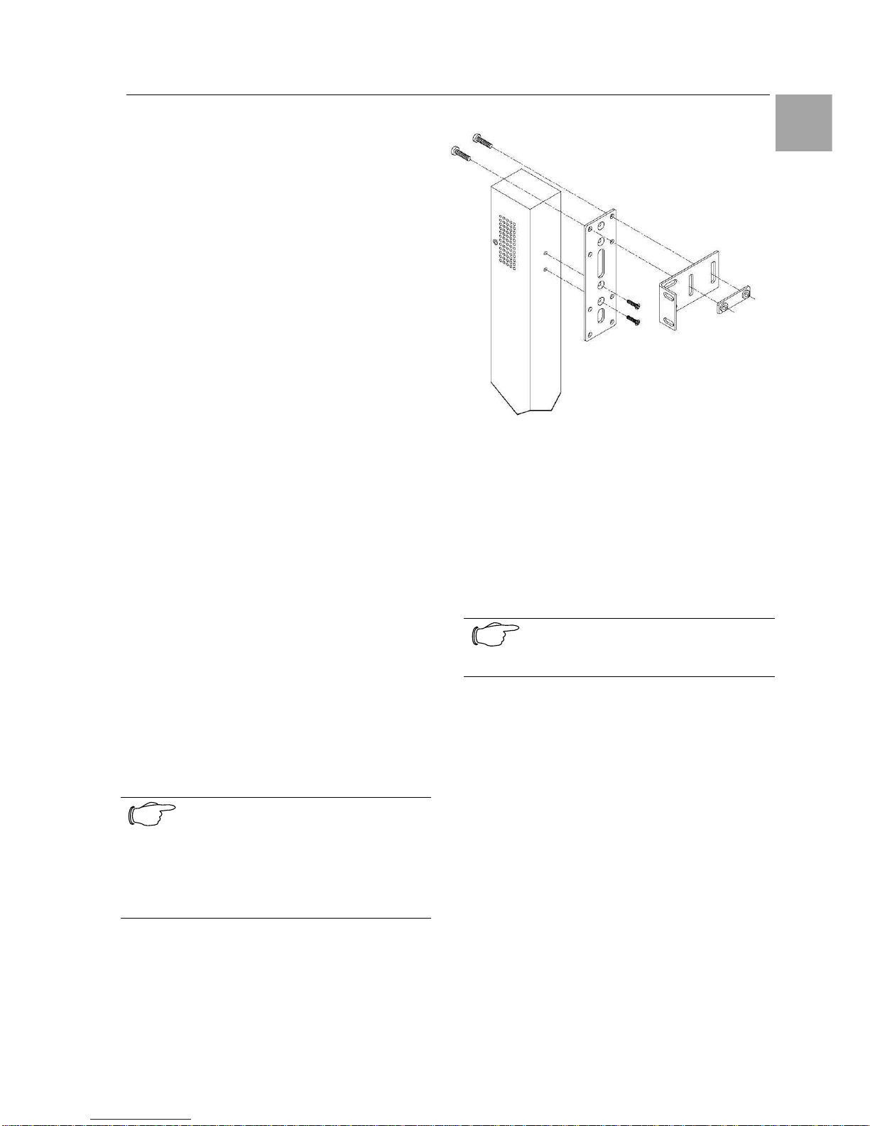
The mounting steps are shown in figure 2.
1. Attach the removable flanges to the mount
points on the rear of the enclosure using M4
screws.
2. Attach the mounting L-brackets to the flanges
with the supplied screws, washers and nut
plates. The slots allow about 1½ inches of
vertical adaptability.
3. Attach the top and bottom brackets to your
rack.
Optionally, the supplied button mounts may be
used for mounting the PDU into cabinets supporting this method of equipment mounting.
Note!
Contact your Rittal Sales Representa-
tive for information regarding custom
bracket design and fabrication services
if you are unable to find a suitable
manner for utilizing the included mounting brackets.
Abb. 2 Mounting the PDU
5.2 Expansion Module
Connect the Expansion Module PDU with the
provided RJ12 crossover cable at the Link port on
the Switched PDU.
Note!
The overall length of the RJ12 cross-
over cable should not exceed 10 feet.
Page 10

Installing 6
10
Switched Power Distribution Unit
EN
6 Installing
Danger!
Only trained specialists may perform
the assembly and installation.
6.1 Security advices
The Rittal Switched PDU may be operated only
with connected protective earth conductor. The
protective earth conductor connection is made by
plugging in the IEC connection cable. This requires that the IEC connection cable at the power
supply side be connected with the protective
earth conductor.
The electrical connection voltage and frequency
must conform to the rated values specified at the
rear of the power supply unit and in the technical
specifications
Before commencing work on the Rittal Switched
PDU, it must be disconnected from the mains
power supply and protected against being reconnected.
Protect the connection cables using cable ties on
the used housing or enclosure.
6.2 Connecting to the Power Source
1. Plug the female end of the power cord
firmly into its connector at the base.
2. Use a screwdriver to tighten the two
screws on the retention bracket.
6.3 Connecting Devices
To avoid the possibility of noise due to arcing:
• Keep the device’s on/off switch in the off posi-
tion until after it is plugged into the outlet.
• Connect devices to the PDU outlets.
Note!
Rittal recommends even distribution of
attached devices across all available
outlets to avoid exceeding the outlet,
branch or phase limitations.
6.4 Connecting to the Unit
Serial (RS232) port
The Switched PDU is equipped with an RJ45
Serial RS-232 port for attachment to a PC or networked terminal server using the supplied RJ45 to
RJ45 crossover cable and RJ45 to DB9F serial
port adapter as required.
Ethernet port
The Switched PDU is equipped with an RJ45
10/100Base-T Ethernet port for attachment to an
existing network. This connection allows access
to the Switched PDU via Telnet or HTML.
The Switched PDU is configured with the following
network defaults to allow unit configuration out-ofthe-box through either Telnet or HTML:
• IP address: 192.168.1.254
• Subnet Mask: 255.255.255.0
• Gateway: 192.168.1.1
The local PC network connection must be configured as noted below:
• IP address: 192.168.1.x (x is 2-253)
• Subnet Mask: 255.255.255.0
Note!
When installed on a DHCP enabled
networks, the following network defaults DO NOT apply as the PDU ships
with DHCP support enabled.
Contact your system administrator for
instructions in reconfiguring the network
connection. Reconfiguration of your
network connection may require a restart to take effect.
Note!
RiWatchIT is NOT supported
Page 11

Operations 7
Switched Power Distribution Unit
11
EN
7 Operations
7.1 Interfaces
The Switched PDU has two interfaces: the HTML
interface accessed via the HTTP enabled
Ethernet connections, and the command line for
serial and Telnet connections.
7.1.1 Outlet Naming and Grouping
Models with a Single Power Infeed
Absolute names are specified by a period (.) followed by a tower letter and outlet number. The
tower letter for the Switched PDU is A and the
tower letter for the optional Expansion Module is
B.
Models with Multiple Power Infeeds
For units with multiple infeed connectors, absolute
names are specified by a period (.) followed by
the tower letter, the infeed letter and outlet number.
Example: The absolute name for outlet 8 on the B
infeed of tower A is .AB8.
Outlets may also be included in one or more
named groups of outlets, enabling you to issue a
command that affects all outlets in a named
group.
7.1.2 Usernames and Passwords
The Switched PDU has one predefined administrative user account (username/password:
admn/admn), and supports a maximum of 128
defined user accounts.
Note!
For security, Rittal recommends removal of the predefined administrative
user account after a new account with
administrative rights have been created.
Only an administrative-level user may perform
operations such as creating/removing user accounts and command privileges, changing passwords and displaying user information. An administrator may also view the status of all sensors and
power inputs.
Usernames may contain from 1-16 characters
and are not case sensitive; spaces are not allowed. Passwords may contain up to 16 characters, and are case sensitive.
Page 12
Operations 7
12
Switched Power Distribution Unit
EN
7.2 HTML Interface
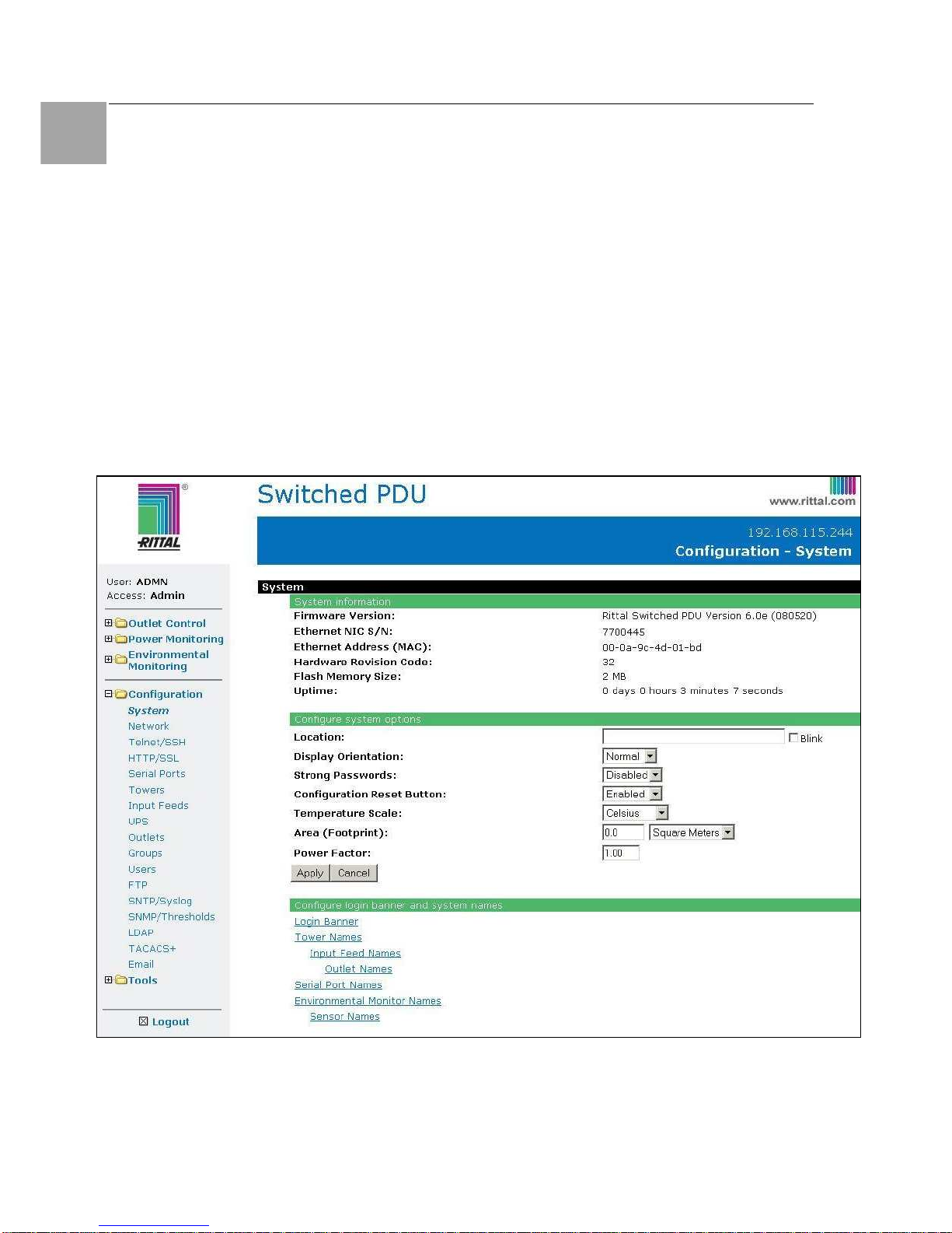
The HTML interface is constructed of three major
components:
1. System Location bar
2. User/Navigation bar
3. Control Screen
The System Location bar displays the PDU’s
location and IP address as well as the current
Control Screen title. The User/Navigation bar
displays the current user and privilege level and
provides access to all HTML pages. The Control
Screen is used to display current data and allow
changes to outlet states or system configuration.
The following sections describe each interface
section/page and their use.
Abb. 3 Example HTML page
1.
2.
3.
Page 13

Operations 7
Switched Power Distribution Unit
13
EN
7.2.1 Logging In
Logging in through HTML requires directing the
HTML client to the configured IP address of the
unit.
To log in by HTML:
In the login window, enter a valid username and
password and press OK.
If you enter an invalid username or password, you
will be prompted again.
You are given three attempts to enter a valid
username and password combination. If all three
fail, the session ends and a protected page will be
displayed.
Note!
The default PDU username/password
is admn/admn
Outlet Control
The Outlet Control section offers access to the
Individual and Group outlet control pages. From
the Individual and Group pages, the user can
review and manipulate power control functions for
all outlets and groups assigned to the current
user. Both pages include the outlet’s absolute
and descriptive names, the Outlet Status reported
to the PDU by the outlet, the current Control State
being applied by the PDU, and the outlet load in
amperes.
Available outlet and group power states may be
set to on, off or reboot.
Individual
The Individual outlet control page displays all
outlets assigned to the current user. The user
may apply on, off or reboot actions to individual,
multiple or all-accessible outlets.
To apply actions to individual or multiple outlets:
In the Individual Outlet Control section, select the
desired action from the Control Action drop-down
menu for each individual outlet to be changed,
and press Apply.
To apply an action to all outlets:
In the Global Control section, select the desired
action from the Control Action drop-down menu
and press Apply.
Group
The Group outlet control page displays all groups
assigned to the current user, as well as the outlets for each group.
To select a group:
Select the group name from the drop-down menu
and press Select. The page will refresh to display all outlets associated to the selected group
name.
To apply an action to a group:
Select the desired action from the drop-down
menu and press Apply.
7.2.2 Power Monitoring
Input Feeds
The Input Feeds page displays:
• Infeed’s absolute and descriptive names
• Infeed status
• Input/branch phase load in amperes
• Input Voltage
• Calculated power usage in Watts.
This page will refresh automatically every 10 seconds.
System
The System page displays:
• Calculated power usage for ALL infeeds
in Watts
• Configured total system area in square
feet or square meters.
• Calculated power usage in Watts/square
foot or square meters.
This page will refresh automatically every 10 seconds.
UPS
The UPS page displays the following information
for each UPS device associated with the PDU:
• Type
• Status
• Voltage
• Hostname/IP address
This page will refresh automatically every 10 seconds.
Page 14

Operations 7
14
Switched Power Distribution Unit
EN
7.2.3 Environmental Monitoring
Sensors
The Sensors page displays:
• Temperature/humidity sensor’s absolute
and descriptive names
• Temperature/humidity sensor readings in
degrees Celsius and percent relative humidity
This page will refresh automatically every 10 seconds.
7.2.4 Configuration
The Configuration section offers access to all unit
configuration options. This section is available to
administrative level users only.
System
The System configuration page is used for reference of system information such as Ethernet NIC
Serial Number, Ethernet MAC address and system
firmware and hardware revisions as well as assignment and maintenance of other system wide
configurations.
For descriptive names, up to 24 alphanumeric
and other typeable characters (ASCII 33 to 126
decimal) are allowed; spaces are not allowed.
Creating a pre-login banner:
Click on the Login Banner link.
On the subsequent Login Banner page, enter a
pre-login banner and press Apply.
Note!
The pre-login banner may be up to
2070 characters in length and is displayed prior to the login prompt. If left
blank, no system banner will be displayed prior to login prompt.
Creating a descriptive system location name:
Enter a descriptive name and press Apply.
Configuring the Input Current LED display
orientation:
Select Normal or Inverted from the drop-down
menu and press Apply.
Enabling or disabling strong password requirements:
The PDU supports enforcement of strong passwords for enhanced security. When enabled, all
new passwords must be a minimum of 8 characters in length with at least one uppercase letter,
one lowercase letter, one number and one special
character.
Acceptable strong passwords:
n0tOnmyw@tch
john2STI?
H3reUgo!
Note!
Strong password requirements also
enforce a minimum change of four character positions when defining new
strong passwords.
Select Enabled or Disabled from the Strong
Passwords drop-down menu and press Apply.
Note!
The strong password requirement is
applied against all new passwords.
Enabling or disabling the external reset button:
Select Enabled or Disabled from the Configuration Reset Button drop-down menu and press
Apply.
Setting the temperature scale:
Select Celsius or Fahrenheit from the Temperature Scale drop-down menu and press Apply.
Setting the system area:
The Total Area value is used to provide calculated
power usage over the total area of the system
displayed in the Power Monitoring pages.
In the Total Area field, enter the area in square
feet for the system and press Apply.
Setting the system input power factor:
The Power Factor value is used to provide calculated power usage displayed in the Power Monitoring pages.
Page 15

Operations 7
Switched Power Distribution Unit
15
EN
Setting the system 3-phase load out-of-bound
threshold:
This setting to use for devices with 3-phase input
voltages to notify of a system imbalance between
the three phases of power.
In the 3-Phase Load Out-of-Bounds Threshold
field, enter a value from 0 to 100% and press Ap-
ply.
Creating a descriptive unit name:
Click on the Tower Names link.
On the subsequent Tower Names page, enter a
descriptive name and press Apply.
Creating a descriptive input feed name:
Click on the Input Feed Names link.
On the subsequent Input Feed Names page, en-
ter a descriptive name and press Apply.
Creating a descriptive outlet name:
Click on the Outlet Names link, which will open
the Outlets configuration page. You can change
the names by clicking on the “Edit” button.
Creating a descriptive serial port name:
Click on the Serial Port Names link, which will
open the Serial Ports configuration page. See
Serial Ports on page 17 for additional information
on creating descriptive serial port names.
You can change the names by clicking on the
“Edit” button.
Creating a descriptive Environmental Monitor
name:
Click on the Environmental Monitor Names link.
On the subsequent Environmental Monitor Names
page, enter a descriptive name and press Apply.
Creating descriptive sensor names:
Click on the Sensor Names link.
On the subsequent Sensor Names page, enter a
descriptive name and press Apply.
Network
The Network configuration page is used for maintenance of the network interface. From this page
an administrator may configure the IP address,
subnet mask, gateway address, DNS addresses
as well as view the link status, speed and duplex
value.
The PDU is configured with the following network
defaults to allow unit configuration out-of-the-box
through either Telnet or HTML:
• IP address: 192.168.1.254
• Subnet Mask: 255.255.255.0
• Gateway: 192.168.1.1
Note!
Contact your system administrator for
instructions in reconfiguring the network
connection. Reconfiguration of your
network connection may require a restart to take effect.
The initial local PC network connection must be
configured as noted below:
• IP address: 192.168.1.x (where x is 2-253)
• Subnet Mask: 255.255.255.0
Note!
The unit must be restarted after network
configuration changes.
Enabling or disabling DHCP support:
Select Enabled or Disabled from the DHCP dropdown menu and press Apply.
Setting the IP address, subnet mask, gateway
or DNS address:
In the appropriate field, enter the IP address, subnet mask, gateway address or DNS address and
press Apply.
Telnet/SSH
The Telnet/SSH configuration page enables or
disables Telnet and SSH support and configures
the port number that the Telnet or SSH server
watches. For more information on SSH see page
49 in 8Advanced Operations.
Page 16

Operations 7
16
Switched Power Distribution Unit
EN
Enabling or disabling Telnet or SSH support:
Select Enabled or Disabled from the appropriate
Server drop-down menu and press Apply.
Changing the Telnet or SSH server port number:
In the appropriate Port field, enter the port number and press Apply.
Enabling or disabling SSH server authentication methods:
The PDU SSH server supports two authentication
methods for security and validation: Password and
Keyboard-Interactive.
Password is an authentication method where the
SSH client gathers username/password credentials and makes the authentication request to the
SSH sever with the credentials. The Password
method is controlled by the SSH client.
Keyboard-Interactive is an authentication method
where the SSH server controls an information field
followed by one or more prompts requesting credential information from the SSH client. The client
gathers credential information keyed-in by the user
and sends it back to the server. The KeyboardInteractive method is controlled by the SSH
server.
Individual enabling and disabling of the Password
and Keyboard-Interactive authentication methods
are supported to allow an SSH client to be forced
to use a specific method. Although both methods
are available, by enabling the KeyboardInteractive method and disabling the Password
method, the SSH client is forced to used Keyboard-Interactive, which is required to display the
login banner.
Note!
At least one authentication method must
be enabled.
Select the Password checkbox and/or the Key-
board-Interactive checkbox and press Apply.
HTTP/SSL
The HTTP/SSL configuration page used to enable
or disable HTTP and SSL support, configure the
port number that the HTTP server watches and
responds to, selection of the method of authentication used and SSL access level.
Enabling or disabling HTTP or SSL support:
Select Enabled or Disabled from the appropriate
Server drop-down menu and press Apply.
Changing the HTTP server port number:
In the HTTP Port field, enter the port number and
press Apply.
Setting the HTTP authentication method:
The PDU HTTP server supports two authentication methods for security and validation of the
username-password: Basic and MD5 digest.
The Basic method uses Base64 encoding to encode and deliver the username-password over
the network to the HTTP server for decoding and
authentication. This basic method is supported
by all web browsers and offers a minimum level of
security.
Note!
The Base64 algorithm is widely known
and susceptible to packet-sniffer attack
for acquisition of the encoded username-password string.
The MD5 digest method provides stronger protection utilizing one-way encoded hash numbers,
never placing the username-password on the
network. Instead, the sending browser creates a
challenge code based on the hash algorithm,
provided username-password and unique items
such as the device IP address and timestamp,
which is compared against the HTTP server internal user database of valid challenge codes. The
MD5 digest method offers a higher level of security than the Basic method but at present is not
supported by all browsers.
Note!
MD5 is known to be fully supported by
Internet Explorer 5.0+
Select Basic or MD5 from the Authentication
drop-down menu and press Apply.
Setting SSL access level:
PDU SSL supports configuration of SSL connections as being either optional or required. The
default access level is set to optional.
Page 17

Operations 7
Switched Power Distribution Unit
17
EN
• Optional –Both non-secure (HTTP) and SSL
encrypted connections (HTTPS) are allowed
access.
• Required – ONLY SSL encrypted connections
(HTTPS) are allowed access.
Select Optional or Required from the Secure
Access drop-down menu and press Apply.
Serial Ports
The Serial Ports configuration page is used for
maintenance of the serial port.
Note!
Pass-Thru connections may only be
initiated from the command line interface
via a Telnet/SSH session.
Setting the data-rate for all serial ports:
Select the serial port data-rate from the dropdown menu and press Apply.
Setting the serial port timeout value:
Enter the timeout value (in minutes) in the Connection Timeout field and press Apply.
Creating a descriptive serial port name:
Click on the Edit link in the Action column next to
the port to be configured.
On the subsequent Serial Port Edit page, enter a
descriptive name up to 24 alphanumeric and other
typeable characters - (ASCII 33 to 126 decimal)
are allowed; spaces are not allowed. Press Apply.
Enabling or disabling serial port active signal
checking:
Click on the Edit link in the Action column next to
the port to be configured.
On the subsequent Serial Port Edit page, select
On or Off from the DSR Check drop-down menu
and press Apply.
Towers
The Towers configuration page is used for assignment and/or editing of:
• Descriptive names
• Serial and Model numbers
• Operation voltage types
Note!
If set at the factory, the serial number,
model number and voltage type WILL
NOT be user-editable.
Creating a descriptive tower name:
In the Tower Name field, enter a descriptive name
and press Apply.
Setting the tower serial number:
In the Serial Number field, enter the serial number
of the unit and press Apply.
Setting the tower model number:
In the Model Number field, enter the model number of the unit and press Apply.
Setting the operational AC or DC voltage type:
From the AC/DC drop-down menu, select AC or
DC, and press Apply.
Setting the operational AC voltage type:
From the 3-Phase drop-down menu, select yes or
no, and press Apply.
Input Feeds
The Input Feeds configuration page is used for
assignment and/or editing of input feed descriptive names, operational voltage and maximum
load capacity.
Creating a descriptive input feed name:
In the Input Feed Name field, enter a descriptive
name and press Apply.
Setting the infeed operational voltage:
In the Input Feed Voltage field, enter a value from
0 to 480 and press Apply.
Setting the infeed maximum load capacity:
In the Input Feed Load Capacity field, enter a
value from 1 to 255 and press Apply.
UPS
The UPS Configuration page is used for adding a
new UPS device and configuring the UPS devices
connected to PDUs.
Page 18

Operations 7
18
Switched Power Distribution Unit
EN
To add a new UPS:
Select the UPS manufacturer type from the Type
drop-down list, type an IP address (or hostname)
for the UPS, and press Apply.
To edit the UPS type:
Under the Action heading, click the Edit link for
the UPS to be configured. The Configuration UPS
page reformats to an edit page where UPS device
settings are configured and UPS devices are
associated with an infeed.
Selecting the UPS type:
Select the UPS manufacturer type from the UPS
Type drop-down list and press Apply.
Editing the UPS Hostname/IP Address:
In the Hostname/IP field, type an IP Address or
Hostname and press Apply.
Editing the UPS SNMP GET community string:
In the SNMP GET Community String field, type
the community string configured on the UPS device and press Apply.
Enabling/Disabling UPS voltage polling:
From the “UPS Voltage Polling” drop-down list,
select Enabled or Disabled and press Apply.
Editing the UPS SNMP port number:
In the SNMP-Port field, type the port number and
press Apply.
Associate the UPS with an infeed:
Select the infeed(s) powered by the UPS and
press Apply.
To remove a UPS:
On the Configuration UPS page, under the Action
heading, click the Remove link for the UPS you
want to remove.
Outlets
The Outlets configuration page is used for assignment and/or editing of outlet sequence and
reboot timers, descriptive names and wakeup
states.
Setting the outlet sequencing interval:
Enter the sequencing interval (in seconds) in the
Sequence Interval field and press Apply.
Setting the outlet reboot delay:
Enter the reboot interval (in seconds) in the Reboot Delay field and press Apply.
Editing the outlet descriptive name:
Click on the Edit link in the Action column next to
the outlet to be configured.
On the subsequent Outlet Edit page, enter a descriptive name. Up to 24 alphanumeric and other
typeable characters (ASCII 33 to 126 decimal) are
allowed; spaces are not allowed. Press Apply.
Changing the outlet wakeup state:
Click on the Edit link in the Action column next to
the outlet to be configured.
On the subsequent Outlet Edit page, select On,
Off or Last from the Wakeup State drop-down
menu and press Apply.
Setting the outlet Post-On delay:
Click on the Edit link in the Action column next to
the outlet to be configured.
On the subsequent Outlet Edit page, enter the
outlet Post-On delay (in seconds) in the Post-On
Delay field and press Apply.
Groups
The Groups configuration page is used for creation and deletion of group and assignment of outlets to groups.
Creating a group:
Enter a descriptive group name in the Group
Name field. Up to 24 alphanumeric and other
typeable characters (ASCII 33 to 126 decimal) are
allowed; spaces are not allowed. Press Apply.
Removing a group:
Click on the Remove link in the Action column for
the group to be removed and press Yes on the
subsequent confirmation window.
Page 19

Operations 7
Switched Power Distribution Unit
19
EN
Adding and Deleting outlets from a group:
Press the Edit link in the Action column for the
associated group.
On the subsequent Group Edit page, select or
deselect outlets to be included in that group.
Press Apply.
Users
The Users configuration page is used for creation
and removal of usernames, assignment of accessible outlets and group, assignment of privilege
levels and the changing of user passwords.
Creating a new user:
Enter a user name in the Username field. Up to
16 alphanumeric and other typeable characters
(ASCII 33 to 126 decimal) are allowed; spaces
are not allowed.
Enter a password for the new user and verify in
the Password and Verify Password fields. For
security, password characters are not displayed.
Press Apply.
Removing a user:
Click on the Remove link in the Action column for
the user to be removed and press Yes on the
subsequent confirmation window.
Changing a user password:
Click on the Edit link in the Action column for the
associated user.
On the subsequent User Edit page, enter a password and verify the new password for the new
user in the Password and Verify Password fields.
For security, password characters are not displayed. Press Apply.
Changing a user’s access privilege level:
The PDU has the following defined privilege levels:
• Admin: Full-access for all configuration, control
(On, Off, Reboot), status and
serial/Pass-Thru ports.
• Power User: Full-access for all control (On,
Off, Reboot), status and
serial/Pass-Thru ports.
• User: Partial-access for control (On, Off, Reboot), status and Pass-Thru of assigned outlets, groups and serial/Pass-Thru ports.
• Reboot-Only: Partial-access for control (Reboot), status and Pass-Thru of assigned
out-
lets, groups and serial/Pass-Thru ports.
• On-Only: Partial-access for control (On), status
and Pass-Thru of assigned
outlets, groups and
serial/Pass-Thru ports.
• View-Only: Partial-access for status and
Pass-Thru of assigned outlets, groups and serial/Pass-Thru ports.
The administrator may also grant administrative
privileges to other user accounts allowing the PDU
to have more than one administrative-level user.
Note!
You cannot remove administrative privileges from the Admn user unless another user has already been given administrative access level privileges created.
Click on the Edit link in the Action column for the
associated user.
On the subsequent User Edit page, select Admin,
Power-User, User, Reboot-only, On-only
or View-only from the Access Level drop-down
menu and press Apply.
Granting or removing Environmental Monitoring viewing privileges:
Click on the Edit link in the Action column for the
associated user.
On the subsequent User Edit page, select Yes or
No from the Environmental Monitoring drop-down
menu and press Apply.
Adding and Deleting outlet access:
Click on the Outlets link in the Access column for
the associated user.
On the subsequent User Outlets page, select or
deselect outlets to be accessed by the user and
press Apply.
Adding and Deleting group access:
Click on the Groups link in the Access column for
the associated user.
On the subsequent User Groups page, select or
deselect group to be accessed by the user and
press Apply.
Adding and Deleting serial port access:
Click on the Ports link in the Access column for
the associated user.
On the subsequent User Ports page, select or
deselect ports to be accessed by the user and
press Apply.
Page 20

Operations 7
20
Switched Power Distribution Unit
EN
FTP
The FTP configuration page is used for setup and
maintenance of all settings required to perform an
FTP firmware upload, configure automatic FTP
updates or system configuration uploads/downloads.
Setting the FTP Host Address:
Enter the IP address or hostname in the Host field
and press Apply.
Setting the FTP username:
Enter the FTP server username in the Username
field, and press Apply.
Setting the FTP password:
Enter the FTP server password in the Password
field, and press Apply.
Setting the file path:
Enter the path of the file to be uploaded in the
Directory field, and press Apply.
Setting the filename for upload:
Enter the filename of the file to be uploaded in the
Filename field, and press Apply.
Testing the FTP upload configuration:
This test validates that the unit is able to contact
and log onto the specified FTP server, download
the firmware file and verify that the firmware file is
valid for this unit.
Press Test.
Enabling or disabling automatic updates:
The PDU features the ability to schedule automatic firmware updates. When enabled and configured, the PDU will regularly check the FTP
server for a new firmware image and upload it.
Select Enabled or Disabled from the drop-down
menu and press Apply.
Setting the automatic update scheduled day:
Select the desired day for the automatic updates
from the drop-down menu and press Apply.
Setting the automatic update scheduled hour:
Select the desired hour for the automatic updates
from the drop-down menu and press Apply.
Enabling or disabling the FTP server:
The PDU features the ability to upload and
download system configuration files to ease implementation across multiple PDU devices.
Select Enabled or Disabled from the drop-down
menu and press Apply.
Note!
The FTP server must be enabled for
configuration upload or download.
SNTP/Syslog
The SNTP/Syslog configuration page is used for
setup and maintenance of SNTP and Syslog support.
Setting the SNTP server address:
Enter the IP address or hostname in the Primary
and/or Secondary Host field and press Apply.
Setting the Local GMT offset:
Select the local offset from GMT value from the
drop-down menu and press Apply.
Setting the Syslog server address:
Enter the IP address or hostname in the Primary
and/or Secondary Host field and press Apply.
Changing the Syslog server port number:
In the Syslog Port field, enter the port number and
press Apply.
SNMP/Thresholds
The SNMP/Thresholds configuration page is used
for setup and maintenance of all settings required
to enable SNMP support, and to provide access
to the trap configuration pages.
Note!
Traps are generated according to a
hierarchical architecture; i.e. if a Tower
Status enters a trap condition, only the
Tower Status trap is generated. Infeed
and Outlet Status traps are suppressed
until the Tower Status returns to Normal.
Page 21

Operations 7
Switched Power Distribution Unit
21
EN
Enabling or disabling SNMP support:
Select Enabled or Disabled from the drop-down
menu and press Apply.
Setting the community strings:
Enter the community string in the appropriate field
and press Apply.
Community strings may be 1 to 24 characters
Setting the trap timer:
Enter a trap timer value in the Error Trap Repeat
Time field and press Apply.
The Error Trap Repeat Time value may be 1 to
65535 (in seconds).
Setting trap destinations:
Enter an IP address or hostname in the appropriate Trap Destination field and press Apply.
Setting IP Restrictions:
Select No Restrictions or Trap Destinations
Only from the IP Restrictions drop-down menu
and press Apply.
Note!
When Trap Destinations Only is selected, SNMP Manager GET and SET
requests are only allowed from the IP
addresses of the defined traps destinations.
Setting the SNMP SysName, SysLocation or
SysContact objects:
In the appropriate field, enter the SysName, SysLocation or SysContact objects and press Apply.
Enabling or disabling tower traps:
Click on the Tower Traps link.
On the subsequent Tower Traps page, select or
deselect the desired traps and press Apply.
Configuring input feed traps and thresholds:
Click on the Input Feed Traps and Thresholds
link.
On the subsequent Input Feed Traps page, select
or deselect the desired traps and press Apply.
For Load traps, enter a maximum load value for
the infeed in the High Load Threshold field and
press Apply.
The default input feed high load threshold is 80%
of the input feed maximum load capacity.
Configuring outlet traps:
Click on the Outlet Traps link.
On the subsequent Outlet Traps and Thresholds
page, select or deselect the desired traps and
press Apply.
Enabling or disabling Environmental Monitor
traps:
Click on the Environmental Monitor Traps link.
On the subsequent page, select or deselect the
desired traps and press Apply.
LDAP
The LDAP configuration page is used for setup
and maintenance of all settings required enabling
LDAP support. For additional information and
configuration requirements.
Enabling or disabling LDAP support:
Select Enabled or Disabled from the LDAP dropdown menu and press Apply.
Changing the LDAP server port:
Enter the port number in the LDAP Port field and
press Apply.
Setting the LDAP server address:
Enter the IP address or hostname in the Primary
and/or Secondary Host field and press Apply.
Enabling or disabling LDAP over TLS/SSL:
Select Yes or No from the Use TLS/SSL dropdown menu and press Apply.
Note!
If LDAP over TLS/SSL is enabled, MD5
binding is disabled.
Setting the LDAP bind password type:
Select Simple or MD5 from the Bind Type dropdown menu and press Apply.
Setting the search bind Distinguished Name
(DN):
Enter the fully qualified distinguished name
(FQDN) in the Search Bind field and press Apply.
Page 22

Operations 7
22
Switched Power Distribution Unit
EN
Setting the search bind password for Distinguished Name (DN):
Enter the Search Bind Password in the Search
Bind Password field and press Apply.
Setting the user search base Distinguished
Name (DN):
Enter the User Search Base DN in the User
Search Base DN field and press Apply.
Setting the user search filter:
Enter the User Search Filter in the User Search
Filter field and press Apply.
Setting the group membership attribute:
Enter the group membership attribute in the
Group Membership Attribute Field and press Ap-
ply.
Setting the group membership value type:
Select the appropriate value from the drop-down
menu and press Apply.
Configuring the authentication order:
Select Remote -> Local or Remote Only from
the drop-down menu and press Apply.
Note!
Rittal recommends NOT setting the authentication order to Remote Only until
the LDAP has been fully configured and
tested.
Configuring LDAP groups:
Click on the LDAP Groups link at the bottom of
the page.
Creating an LDAP group:
Enter a descriptive group name in the LDAP
Group Name field. Up to 24 alphanumeric and
other typeable characters (ASCII 33 to 126 decimal) are allowed; spaces are not allowed. Press
Apply.
Removing an LDAP group:
Click on the Remove link in the Action column for
the group to be removed and press OK on the
subsequent confirmation window.
Changing an LDAP group’s access privilege level:
Click on the Edit link in the Action column for the
associated LDAP Group.
On the subsequent LDAP Group - Edit page,
select Admin, User, On-only, Reboot-only,
Power-user or View-only from the Access Level
drop-down menu and press Apply.
Granting or removing Environmental Monitoring
viewing privileges:
Click on the Edit link in the Action column for the
associated LDAP Group.
On the subsequent LDAP Group - Edit page,
select Yes or No from the Environmental Monitoring drop-down menu and press Apply.
Adding and Deleting outlet access:
Click on the Outlets link in the Access column for
the associated LDAP Group.
On the subsequent LDAP Group - Outlets page,
select or deselect outlets to be accessed by the
LDAP Group and press Apply.
Adding and Deleting outlet group access:
Click on the Groups link in the Access column for
the associated LDAP Group.
On the subsequent LDAP Group - Groups page,
select or deselect outlet groups to be accessed by
the LDAP Group and press Apply.
Adding and Deleting serial port access:
Click on the Ports link in the Access column for
the associated LDAP Group.
On the subsequent LDAP Group - Ports page,
select or deselect ports to be accessed by the
LDAP Group and press Apply.
TACACS+
The TACACS+ configuration page is used for
setup and maintenance of all settings required to
enable TACACS+ support.
Enabling or disabling TACACS+ support:
Select Enabled or Disabled from the TACACS+
drop-down menu and press Apply.
Changing the TACACS+ server port:
Enter the port number in the Port field and press
Apply.
Page 23

Operations 7
Switched Power Distribution Unit
23
EN
Setting the TACACS+ server address:
Enter the IP address or hostname in the Primary
and/or Secondary Host field and press Apply.
Configuring the authentication order:
Select Remote -> Local or Remote Only from
the drop-down menu and press Apply.
Setting the TACACS+ encryption key:
Enter a key and verify the new key the Encryption
Key and Verify New Encryption Key fields. Press
Apply.
For security, key characters are not displayed.
Configuring TACACS+ privilege levels:
Click on the TACACS+ Privilege Levels link at
the bottom of the page.
Changing an TACACS+ Privilege Level’s access
privilege level:
Click on the Edit link in the Action column for the
associated TACACS+ Privilege Level.
On the subsequent TACACS+ Privilege Level Edit page, select Admin, User, On-only, Re-
boot-only, Power-user or View-only from the
Access Level drop-down menu and press Apply.
Granting or removing Environmental Monitoring
viewing privileges:
Click on the Edit link in the Action column for the
associated TACACS+ privilege level.
On the subsequent TACACS+ Privilege Level Edit page, select Yes or No from the Environmental Monitoring drop-down menu and press
Apply.
Adding and Deleting outlet access:
Click on the Outlets link in the Access column for
the associated TACACS+ Privilege Level.
On the subsequent LDAP Group - Outlets page,
select or deselect outlets to be accessed by the
TACACS+ Privilege Level and press Apply.
Adding and Deleting outlet group access:
Click on the Groups link in the Access column for
the associated TACACS+ Privilege Level.
On the subsequent LDAP Group - Groups page,
select or deselect outlet groups to be accessed by
the TACACS+ Privilege Level and press Apply.
Adding and Deleting serial port access:
Click on the Ports link in the Access column for
the associated TACACS+ Privilege Level.
On the subsequent LDAP Group - Ports page,
select or deselect ports to be accessed by the
TACACS+ Privilege Level and press Apply.
E-Mail
The Email configuration page is used for setup
and maintenance Email log support.
Enabling or disabling Email support:
Select Enabled or Disabled from the Email Notifications drop-down menu and press Apply.
Setting the SMTP server address:
Enter the IP address or hostname in the SMTP
Host field and press Apply.
Changing the SMTP server port:
Enter the port number in the SMTP Port field and
press Apply.
Setting the ‘From’ email address:
Enter the ‘from’ email address in the ‘From’ Address field and press Apply.
Setting the ‘To’ email address:
Enter the ‘to’ email address in the Primary or
Secondary ‘Send To’ Address field and press
Apply.
Enabling or disabling event type notifications:
Select Enabled or Disabled from the Include…Messages drop-down menus and press
Apply.
Features
The Features configuration page is used for activation maintenance of special features purchased
from Rittal. From this page an administrator may
review all activated features as well as activate
newly purchased features.
To activate a special feature:
In the Feature Key Value field, enter the activation key provided by Rittal and press Apply.
Page 24

Operations 7
24
Switched Power Distribution Unit
EN
Note!
A restart of the PDU is required after
activating new special features.
7.2.5 Tools
The Tools section contains access to rebooting
the unit, uploading new firmware as well as resetting the unit to factory defaults. This section is
available to administrative level users only.
Ping
The Ping feature may be used to test the PDU`s
ability to contact another Ethernet enabled device’s IP address. For LDAP support, it may also
be used to test the configuration of the Domain
Name server IP address by testing for proper
name resolution.
Change Password
The Change Password feature allows users to
change their own password.
Note!
An administrator can always assign a
new password.
Changing a password:
Enter the current password, enter a new password and verify the new password. Press Apply.
View Log
The View Log feature enables viewing of the internal system log. This feature logs all authentication attempts, power actions, configuration
changes and other system events. The system
memory stores more than 4000 entries in a continuously aging log. For permanent off-system
log storage, the Syslog protocol is supported.
Note!
The system log is viewable only by users with administrative privileges.
Reviewing the system log:
Click on the First Page, Last Page, Previous
Page or Next page link to navigate through the
log.
Restart
Performing a warm boot:
Select the Restart from the Action drop-down
menu and press Apply.
Note!
System user/outlet/group configuration
or outlet states are NOT changed or
reset with this command.
Generating a new SSL X.509 certificate:
Select the Restart and generate a new X.509
certificate from the Action drop-down menu
and press Apply.
Computing new SSH security keys:
Select the Restart and compute new SSH keys
from the Action drop-down menu and press Ap-
ply.
7.3 Command Line Interface
Logging In
Logging in through Telnet requires directing the
Telnet client to the configured IP address of the
unit.
Logging in through the Console (RS232) port
requires the use of a terminal or terminal emulation software configured to support ANSI or
VT100 and a supported data rate (300, 1200,
2400, 4800, 9600, 19200, 38400, 57600, or
115200 BPS) - 8 data bits-no parity-one stop bit
and Device Ready output signal (DTR or DSR).
The default data rate is 9600.
To log in by RS-232 or Telnet:
1. Press Enter. The following appears, where
x.xx is the firmware version:
Rittal Switched PDU - Version x.xx
Username:
2. At the Username: and Password: prompts,
enter a valid username and password. And
press Enter.
Note!
Logging in by Telnet will automatically
open a session. It is not necessary to
press Enter.
Page 25

Operations 7
Switched Power Distribution Unit
25
EN
When you enter a valid username and password,
the command prompt (Switched PDU:) appears. If
a location identifier was defined, it will be displayed before the Switched PDU: prompt.
Commands may be entered in any combination of
uppercase and lowercase. All command characters must be entered correctly; there are no command abbreviations. A user must have administrative privileges to use the administration commands. The following tables list and briefly describe each command.
Operations Command Summary
Command Description
Connect Connects to a serial/Pass-Thru port
Envmon Displays the status of the integrated
Environmental Monitor
ILoad Displays the status of the infeeds
IStat Displays the status of the infeeds
List Group Lists all assigned outlets for a group
name
List Groups Lists all accessible groups for the current
user
List Outlets Lists all accessible outlets for the current
user
List Ports Lists all accessible serial/Pass-Thru ports
for the current user
Login Ends the current session and brings up
the Username: prompt
Logout Ends a session
Off Turns one or more outlets off
On Turns one or more outlets on
Password Changes the password for the current
user
Quit Ends a session
Reboot Reboots one or more outlets
Status Displays the on/off status of one or more
outlets
UPSStat Displays the status of the associated
UPSs
Page 26

Operations 7
26
Switched Power Distribution Unit
EN
Administrative Command Summary
Add Grouptouser Grants a user access to one
or more groups
Add Outlettogroup Adds an outlet to a group
name
Add Outlettouser Grants a user access to one
or all outlets
Add Porttouser Grants a user access to one
or all serial/Pass-Thru ports
Create Group Adds a group name
Create UPS Adds a UPS association
Create User Adds a user account
Delete Groupfromuser Removes access to one or
more groups for a user
Delete Outletfromgroup Deletes an outlet from a
group name
Delete Outletfromuser Removes access to one or
all outlets for a user
Delete Portfromuser Removes access to one or
all serial/Pass-Thru ports
List User Displays all accessible out-
lets/groups/ports for a user
List Users Displays privilege levels for
all users
Remove Group Deletes a group name
Remove UPS Deletes a UPS association
Remove User Deletes a user account
Restart Performs a warm boot
Set Banner Set the pre-login banner text
Set DHCP Enables or disables DHCP
support
Set DNS Sets the IP address of the
Domain Name server
Set Envmon Name Specifies a descriptive field
fro the integrated Environ-
mental Monitor
Set Envmon THS Name Specifies a descriptive field
for a temperature-humidity
sensor
Set FTP Autoupdate Day Sets the automatic FTP
update day
Set FTP Autoupdate Hour Sets the automatic FTP
update hour
Set FTP Autoupdate Enables or disables auto-
matic FTP update support
Set FTP Directory Specifies the directory for the
file to be uploaded
Set FTP Filename Specifies the file to be up-
loaded via FTP
Set FTP Filepath Specifies the directory for the
file to be uploaded
Set FTP Host Sets the FTP Host IP ad-
dress or hostname
Set FTP Password Sets the password for the
FTP Host
Set FTP Server Enables or disables the FTP
server
Set FTP Username Sets the username for the
FTP Host
Set Gateway Sets the Gateway of the PDU
Set HTTP Port Specifies the target port for
HTTP access
Set HTTP Security Specifies the HTTP server
authentication method
Set HTTP Enables or disables HTTP
access
Set Infeed Loadmax Specifies the maximum load
capacity for the infeed
Set Infeed Name Specifies a descriptive field
for the infeed
Set Infeed Voltage Specifies the nominal input
voltage for the infeed
Set Ipaddress Sets the IP address of the
PDU
Set LDAP UseTLS Enables or disables LDAP
over TLS/SSL support
Set Location Specifies a descriptive field
for the HTML control screen
and login banner
Set Option Button Enables or disables the
external configuration reset
button
Set Option Display Sets the LED orientation for
external Current displays
Set Option More Enables or disables the
‘more’ prompt
Set Option StrongPasswords Enables or disables strong
password requirements
Set Outlet Name Specifies a descriptive field
for a device attached to an
outlet
Set Outlet PostOnDelay Sets the Post-On delay for
an outlet
Set Outlet RebootDelay Sets the reboot delay for all
outlets
Set Outlet SeqInterval Sets the sequencing interval
for all outlets
Set Outlet Wakeup Sets the wakeup state for an
outlet
Set Port Dsrchk Sets the DSR active signal
checking for a serial/PassThru port
Set Port Name Specifies a descriptive field
for a serial/Pass-Thru port
Set Port Speed Set the connection speed for
all serial/Pass-Thru ports
Set Port Timeout Sets the inactivity timer for
Pass-Thru sessions
Set SNMP IP Restrict Allows SNMP GET and SET
requests from defined traps
destinations only
Set SNTP Sets the IP address or host-
name of the SNTP servers
Set SNTP GMTOffset Sets the local GMT offset
applied to the SNTP
date/time
Set Subnet Sets the Subnet Mask of the
PDU
Page 27

Operations 7
Switched Power Distribution Unit
27
EN
Set System Area Specifies to total square feet
for the system
Set System Balance Specifies the percent out-of-
balance threshold for 3phase systems
Set System PF Specifies the power factor
value for the system
Set Telnet Port Sets the Telnet server port
number
Set Telnet Enables or disables Telnet
access
Set Tower 3Phase Specifies the AC voltage type
for the tower
Set Tower Model Specifies the model number
for the tower
Set Tower Name Specifies a descriptive field
for the tower
Set Tower ProdSN Specifies the serial number
for the tower
Set Tower Specifies the AC or DC
voltage type for the tower
Set UPS AddInfeed Adds an infeed association to
a UPS
Set UPS DelInfeed Deletes an infeed association
from a UPS
Set UPS GETComm Sets the UPS ‘get’ commu-
nity string
Set UPS Host Sets the UPS Host IP ad-
dress or hostname
Set UPS Port Specifies the target port for a
UPS
Set UPS Type Sets the UPS type
Set UPS VPoll Enables or disables UPS
voltage polling
Set User Access Sets the access level for a
user
Set User Envmon Grants or removes privileges
to view input/environmental
monitoring status
Set User Password Changes the password for a
user
Show FTP Displays FTP configuration
information
Show Infeeds Displays infeed configuration
information
Show Network Displays network configura-
tion information
Show Options Displays system option
information
Show Outlets Displays configuration infor-
mation for all outlets
Show Ports Displays serial/Pass-Thru
port configuration information
Show SNTP Displays SNTP configuration
information
Show System Displays system configura-
tion information
Show Towers Displays tower configuration
information
Show UPS Displays UPS configuration
information
Version Displays the PDU firmware
version
Page 28

Operations 7
28
Switched Power Distribution Unit
EN
To display the names of commands that you
may execute:
At the command prompt, press Enter. A list of
valid commands for the current user appears.
Operations Commands
Operations commands manage outlet states,
provide information about the PDU environment
and control session operations.
Turning outlets on:
The On command turns on one or more outlets.
When the command completes, a display indicating all outlets affected and their current states will
be displayed.
To turn outlets on:
At the Switched PDU: prompt, type on, followed
by an outlet name, and press Enter, or
Type on, followed by a group name, and press
Enter, or
Type on all and press Enter.
Examples
The following command turns the second outlet
on, using the outlet’s absolute name:
Switched PDU: on .a2<Enter>
The following command turns on all the outlets in
the group named ServerGroup_1:
Switched PDU: on ServerGroup_1<Enter>
Turning outlets off:
The Off command turns off one or more outlets.
When the command completes, a display indicating all outlets affected and their current states will
be displayed.
To turn outlets off:
At the Switched PDU: prompt, type off, followed
by an outlet name, and press Enter, or
Type off, followed by a group name, and press
Enter, or
Type off all and press Enter
Examples
The following command turns off the outlet named
FileServer_1:
Switched PDU: off FileServer_1<Enter>
The following command turns off all outlets:
Switched PDU: off all<Enter>
Rebooting outlets:
The Reboot command reboots one or more outlets. This operation turns the outlet(s) off, delays
for a user configurable period and then turns the
outlet(s) on. When the command completes, a
display indicating all outlets affected and their
current states will be displayed.
Note!
It is necessary to reissue the Status
command to verify that the outlets have
rebooted.
To reboot one or more outlets:
At the Switched PDU: prompt, type reboot, followed by an outlet name, and press Enter, or
Type reboot, followed by a group name, and
press Enter, or
Type reboot all and press Enter.
Example
The following command reboots all the outlets in
the group named ServerGroup_1:
Switched PDU: reboot ServerGroup_1<Enter>
Displaying outlet status:
The Status command displays the on/off status of
one or more outlets. The command displays the
status of only those outlets for which the current
username has power control access.
This display includes the outlet absolute and descriptive names, the Outlet State reported to the
PDU by the outlet and the current Control State
being applied by the PDU. If you do not specify
any parameter with this command, the status of
all accessible outlets is displayed.
Note!
If the user has access to more than 16
total outlets, the Status command will
display the first 16 outlets with a prompt
to view the remaining outlets.
Page 29

Operations 7
Switched Power Distribution Unit
29
EN
To display on/off status of one or more outlets:
At the Switched PDU: prompt, type status, followed by an outlet name, and press Enter, or
Type status, followed by a group name, and
press Enter, or
Type status and press Enter.
Examples
The following command displays the on/off status
of the outlet named FileServer_1:
Switched PDU: status FileServer_1<Enter>
Outlet Outlet Outlet Control
ID Name State State
.A3 FileServer_1 On On
The following command displays the on/off status
of all accessible outlets:
Switched PDU: status<Enter>
Outlet Outlet Outlet Control
ID Name State State
.A1 DataServer_1 On On
.A2 WebServer_1 On On
.A3 FileServer_1 On On
.A4 TowerA_Outlet4 On On
.A5 TowerA_Outlet5 On On
.A6 TowerA_Outlet6 On On
.A7 TowerA_Outlet7 On On
.A8 TowerA_Outlet8 On On
.A9 TowerA_Outlet9 On On
.A10 TowerA_Outlet10 On On
.A11 TowerA_Outlet11 On On
.A12 TowerA_Outlet12 On On
.A13 TowerA_Outlet13 On On
.A14 TowerA_Outlet14 On On
.A15 TowerA_Outlet15 On On
.A16 TowerA_Outlet16 On On
More (Y/es N/o):
The following command displays the on/off status
for outlets in the group ServerGroup_1:
Switched PDU: status ServerGroup_1<Enter>
Group: ServerGroup_1
Outlet Outlet Outlet Control
ID Name State State
.A1 DataServer_1 On On
.A2 WebServer_1 On On
.A3 FileServer_1 On On
Displaying accessible outlets:
The List Outlets command displays accessible
outlets for the current user. The display includes
the absolute and descriptive name of all outlets
assigned to the current user.
To display accessible outlets:
At the Switched PDU: prompt, type list outlets
and press Enter.
Example
The follow command displays all accessible outlets for the current user:
Switched PDU: list outlets<Enter>
Outlet Outlet
ID Name
.A1 DataServer_1
.A2 WebServer_1
Displaying accessible groups:
The List Groups command displays accessible
groups for the current user.
To display accessible groups:
At the Switched PDU: prompt, type list groups
and press Enter.
Example
The follow command displays all accessible
groups for the current user:
Switched PDU: list groups<Enter>
Groups:
ServerGroup_1
RouterGroup_1
Displaying outlets assigned to a group:
The List Group command displays outlets assigned to the specified group name.
To display outlets assigned to a group:
At the Switched PDU: prompt, type list group,
followed by the group name and press Enter.
Example
The follow command displays the outlets assigned to the group ServerGroup_1:
Switched PDU: list group ServerGroup_1<Enter>
Group: ServerGroup_1
Outlet Outlet
ID Name
.A1 DataServer_1
.A2 WebServer_1
.A3 FileServer_1
Page 30

Operations 7
30
Switched Power Distribution Unit
EN
Displaying accessible serial ports:
The List Ports command displays accessible serial ports for the current user.
To display accessible serial ports:
At the Switched PDU: prompt, type list ports and
press Enter.
Example
The follow command displays all accessible serial
ports for the current user:
Switched PDU: list ports<Enter>
Port Port
ID Name
Console Console
Displaying infeed status:
The Istat or Iload command displays the status of
one or more infeed.
This display includes the infeed absolute and
descriptive names and the Input Status and current Load reported to the PDU by the infeed,
branch or phase.
To display status of one or more infeeds:
Type istat and press Enter, or
Type iload and press Enter.
Examples
The following command displays the infeed
status:
Switched PDU: istat
Input Input Input Input
Feed ID Feed Name Status Load
.AA HQ_1_Infeed_A On 10.5 Amps
Connecting to a serial device:
The Connect command allows Pass-Thru serial
connection to devices attached to the standard
serial port (Console).
To connect to a serial device:
At the Switched PDU: prompt, type connect console and press Enter.
To disconnect from a serial device:
Type !*break and press Enter.
Displaying the status of the Environmental
Monitor:
The Envmon command displays the status of the
integrated Environmental Monitor.
By default, only administrative user accounts are
allowed access to the Envmon command. An
administrator may user the Set User Envmon
command to enable and disable access for other
user accounts.
To display the status of the Environmental Monitor:
At the Switched PDU: prompt, type envmon and
press Enter.
Example
The following command displays the status of the
Environmental Monitor.
Switched PDU: envmon<Enter>
Environmental Monitor .A
Name: Florida_HQ_1 Status: Normal
Temperature/Humidity Sensors
ID Name Temperature Humidity
.A1 Temp_Humid_Sensor_A1 Not Found Not Found
.A2 T/H2_Florida_HQ_1 23.5 Deg. C 22 % RH
Changing a password:
The Password command changes the current
user’s password. For security, when you type a
password, the characters are not displayed on the
screen. See Usernames and Passwords for more
information.
To change a password:
At the Switched PDU: prompt, type password
and press Enter.
At the Enter Current Password: prompt, type the
current password and press Enter.
At the Enter New Password: prompt, type the new
password and press Enter. Passwords may contain 1-16 characters.
At the Verify Password: prompt, retype the new
password and press Enter.
Starting a new session:
The Login command activates the Username:
prompt. The current session ends, allowing a user
to log in and start a new session under a different
username.
To start a new session:
At the Switched PDU: prompt, type login and
press Enter. The Username: prompt appears.
Page 31

Operations 7
Switched Power Distribution Unit
31
EN
Ending a session:
The Quit or Logout commands ends a session. A
session ends automatically when no activity is
detected for five minutes, or upon loss of connection.
To end a session:
At the Switched PDU: prompt, type quit and
press Enter, or
Type logout and press Enter.
Displaying UPS status:
The UPSStat command displays the status of one
or more UPS devices associated with the PDU
unit.
The display includes UPS index number, type,
line/battery status, and reported voltage.
Note!
Access to this command requires enabling user privileges for environmental
monitoring using the Set User Envmon
command.
To display status of one or more UPS devices:
At the Switched PDU: prompt, type upsstat and
press Enter.
Example
The following command displays the UPS status:
Switched PDU: upsstat<Enter>
UPS UPS UPS UPS
Index Type Status Voltage
1 Liebert On Utility 119.9
2 Powerware On Battery 120.0
7.3.1 Administration Commands
Administration commands may only be issued by
a user with administrative privileges, such as the
predefined Admn user or another user who has
been granted administrative privileges with the
Set User Admnpriv command.
User Administration
Creating a user account:
The Create User command creates a user account with the specified username and password.
To create a user account:
At the Switched PDU: prompt, type create user,
optionally followed by a 1-16 character username
(Spaces are not allowed, and usernames are not
case sensitive). Press Enter.
At the Password: prompt, type a password of 1-16
alphanumeric and other typeable characters (ASCII 33 to 126 decimal) are allowed; passwords
are case sensitive. Press Enter.
At the Verify Password: prompt, retype the password. Press Enter.
Example
The following command creates the user account
JaneDoe:
Switched PDU: create user JaneDoe<Enter>
Password: <Enter>
Verify New Password: <Enter>
For security, password characters are not displayed.
Removing a user account:
The Remove User command removes a user
account.
Note!
You may remove the predefined user
account Admn only if another user account has been granted administrative
privileges using the Set User Admnpriv
command.
To remove a user account:
At the Switched PDU: prompt, type remove user,
optionally followed by a username. Press Enter.
Changing a password:
The Set User Password command changes a
user’s password. For security, when you type a
password, the characters are not displayed on the
screen. See Usernames and Passwords for more
information.
To change a password:
At the Switched PDU: prompt, type set user
password, followed by a username and press
Enter.
At the Password: prompt, type the new password
and press Enter. Passwords may contain 1-16
characters.
Page 32

Operations 7
32
Switched Power Distribution Unit
EN
At the Verify Password: prompt, retype the new
password and press Enter.
Example
The following command changes the password
for the user JohnDoe:
Switched PDU: set user password johndoe<Enter>
Password: <Enter>
Verify Password: <Enter>
For security, password characters are not displayed.
Setting user access level privileges:
The Set User Access command sets the access
level privileges for a user. The PDU has the
following defined access privilege levels; Admin,
Power User, User, Reboot-Only, On-Only and
View-Only.
The administrator may also grant administrative
privileges to other user accounts allowing the PDU
to have more than one administrative-level user.
Note!
You cannot remove administrative privileges from the Admn user unless another user has already been given administrative access level privileges created.
To set the access level privilege for a user:
At the Switched PDU: prompt, type set user access, followed by admin, poweruser, user, rebootonly, ononly or viewonly, optionally followed by a username and press Enter.
Examples
The following command sets the user access
level for JohnDoe to Admin:
Switched PDU: set user access admin
johndoe<Enter>
The following command sets the user access
level for JaneDoe to User:
Switched PDU: set user access user janedoe<Enter>
Granting and removing input load viewing
privileges:
The Set User Envmon command grants or removes input status viewing privileges to/from a
user.
To grant or remove input load viewing privileges for
a user:
At the Switched PDU: prompt, type set user envmon followed by on or off, optionally followed
by a username and press Enter.
Example
The following command grants input load privileges to the user JohnDoe:
Switched PDU: set user envmon on
johndoe<Enter>
Displaying the access privilege levels:
The List Users command displays all defined
users with their access privilege level.
To display user access privilege levels:
At the Switched PDU: prompt, type list users and
press Enter.
Example
The following command displays all users with
their access privilege level:
Switched PDU: list users<Enter>
User Privilege Environmental
Name Level Monitoring
JOHNDOE Admin Allowed
JILLDOE Power-User Allowed
JANEDOE User Allowed
JAKEDOE Reboot-Only Not Allowed
JOSEYDOE On-Only Not Allowed
JOEDOE View-Only Not Allowed
Adding outlet access to a user:
The Add OutletToUser command grants a user
access to one or all outlets. To grant access for
more than one outlet, but not all outlets, you must
use multiple Add OutletToUser commands.
To grant outlet access to a user:
At the Switched PDU: prompt, type add outlettouser, optionally followed by an outlet name and
a username. Press Enter, or
Type add outlettouser all, followed by a user-
name and press Enter.
Page 33

Operations 7
Switched Power Distribution Unit
33
EN
Examples
The following commands grant the user JaneDoe
access to outlets A1 and Webserver_1:
Switched PDU:add outlettouser .a1 janedoe<Enter>
Switched PDU:add outlettouser WebServer_1
janedoe<Enter>
Deleting outlet access for a user:
The Delete OutletFromUser command removes a
user’s access to one or all outlets. You cannot
remove access to any outlet for an administrative
level user.
To delete outlet access for a user:
At the Switched PDU: prompt, type delete outletfromuser, optionally followed by an outlet name
and a username. Press Enter, or
Type delete outletfromuser all, followed by a
username and press Enter.
Adding group access to a user:
The Add GroupToUser command grants a user
access to a group. To grant access for more than
one group, you must use multiple Add GroupToUser commands.
To grant group access to a user:
At the Switched PDU: prompt, type add grouptouser, optionally followed by a group name and
a username. Press Enter.
Examples
The following commands grants to user JaneDoe
access to the groups ServerGroup_1 and
ServerGroup_2:
Switched PDU:add GroupToUser ServerGroup_1
janedoe<Enter>
Switched PDU:add GroupToUser ServerGroup_2
janedoe<Enter>
Deleting group access for a user:
The Delete GroupFromUser command removes a
user’s access to a group. You cannot remove
access to any group for an administrative level
user.
To delete group access for a user:
At the Switched PDU: prompt, type delete
GroupFromUser, optionally followed by a group
name and a username. Press Enter.
Adding serial port access to a user:
The Add PortToUser command grants a user
access to the serial port.
To grant serial port access to a user:
At the Switched PDU: prompt, type add porttouser console and a username. Press Enter.
Deleting serial port access for a user:
The Delete PortFromUser command removes a
user’s access to the serial port. You cannot remove access to the serial port for an administrative level user.
To delete serial port access for a user:
At the Switched PDU: prompt, type delete portfromuser console and a username. Press Enter.
Displaying user outlet, group and serial port
access:
The List User command displays all accessible
outlets, groups and serial ports for a user.
To display user outlet, group and serial port access:
At the Switched PDU: prompt, type list user,
optionally followed by a username. Press Enter.
Example
The following command displays information
about the user JaneDoe:
Switched PDU: list user janedoe<Enter>
Username: JANEDOE
Outlet Outlet
ID Name
.A1 DataServer_1
.A2 WebServer_1
Groups:
ServerGroup_1
ServerGroup_2
More (Y/es N/o): Y
Ports:
Port Port
ID Name
Console Console
JaneDoe may access the following outlets,
groups and serial ports: outlet A1 which has a
descriptive name of DataServer_1, outlet A2
which has a descriptive name of WebServer_1,
group ServerGroup_1 group ServerGroup_2, and
Console serial port.
Page 34

Operations 7
34
Switched Power Distribution Unit
EN
Outlet Administration
Setting the sequencing interval:
The Set Outlet SeqInterval commands sets the
power on sequencing interval for all outlets.
To set the sequencing interval:
At the Switched PDU: prompt, type set outlet
seqinterval all, followed by a value from 0 to 15
(in seconds) and press Enter.
Setting the reboot delay:
The Set Outlet RebootDelay commands sets the
reboot delay for all outlets.
To set the sequencing interval:
At the Switched PDU: prompt, type set outlet
rebootdelay all, followed by a value from 5 to 60
(in seconds) and press Enter.
Creating a descriptive outlet name:
The Set Outlet Name command assigns a descriptive name to an outlet. You may use this
name in commands that require an outlet name
as an alternative to using the outlet’s absolute
name.
To create an outlet name:
At the Switched PDU: prompt, type set outlet
name followed by the absolute outlet name, then
a descriptive name of up to 24 alphanumeric and
other typeable characters - (ASCII 33 to 126
decimal) are allowed; spaces are not allowed;
outlet names are not case sensitive. Press Enter.
Example
The following command adds the descriptive
name DataServer_1 to outlet .a1:
Switched PDU: set outlet name .a1 DataServer_1<Enter>
Setting the outlet wakeup state:
The Set Outlet Wakeup command set the default
wakeup state for that outlet. In the event of a
system-wide power loss, this state will be applied
to the outlet when power is restored.
The wakeup state may be set to On, Off or Last.
Upon restoration of system power; If set to On,
the PDU will apply power to that outlet. If set to
Off, the PDU will not apply power to that outlet. If
set to Last, the PDU will apply the last known
power state.
To set the wakeup state:
At the Switched PDU: prompt, type set outlet
wakeup, followed by on, off or last and the outlet
name. Press Enter.
Example
The following command sets the wakeup state for
outlet .a1 to off:
Switched PDU: set outlet wakeup off .a1<Enter>
Setting the outlet Post-On delay:
The Set Outlet PostOnDelay command is used
set the Post-On delay for an outlet. This feature
allows the administrator to manage boot dependencies during power-on sequencing or group
commands by delaying the sequencing of subsequent outlets after an outlet has been powered
on.
Note!
This delay is applied in addition to the
general sequencing interval.
To set the outlet Post-On delay
At the Switched PDU: prompt, type set outlet
postondelay, followed by a value from 0 to 900
(in seconds) and press Enter.
Example
The following command set the Post-On delay for
outlet .a5 to 90 seconds:
Switched PDU: set outlet postondelay .a5
90<Enter>
Displaying outlet information:
The Show Outlets command displays information
about all outlets. This information includes:
• Sequencing and reboot timer values
• Descriptive outlet name, if applicable
• Outlet wakeup state and Post-On settings
To display outlet information:
At the Switched PDU: prompt, type show outlets
and press Enter.
Page 35

Operations 7
Switched Power Distribution Unit
35
EN
Example
The following command displays all outlet information:
Switched PDU: show outlets<Enter>
Outlet Outlet Wakeup Post-On
ID Name State Delay(sec)
.A1 DataServer_1 On 0
.A2 WebServer_1 On 0
.A3 FileServer_1 On 0
.A4 TowerA_Outlet4 On 0
.A5 TowerA_Outlet5 On 90
.A6 TowerA_Outlet6 On 0
.A7 TowerA_Outlet7 On 0
.A8 TowerA_Outlet8 On 0
.A9 TowerA_Outlet9 On 0
.A10 TowerA_Outlet10 On 0
.A11 TowerA_Outlet11 On 0
.A12 TowerA_Outlet12 On 0
.A13 TowerA_Outlet13 On 0
.A14 TowerA_Outlet14 On 0
.A15 TowerA_Outlet15 On 0
.A16 TowerA_Outlet16 On 0
More (Y/es N/o):
Outlet Options:
Sequence Interval: 2 seconds
Reboot Delay: 15 seconds
Input Feed Administration
Creating a descriptive infeed name:
The Set Infeed Name command assigns a descriptive name to an infeed. This descriptive
name is displayed when the Show Traps command is issued.
To create a infeed name:
At the Switched PDU: prompt, type set infeed
name followed by the absolute infeed name, then
a descriptive name of up to 24 alphanumeric and
other typeable characters - (ASCII 33 to 126
decimal) are allowed; spaces are not allowed.
Press Enter.
Example
The following command adds the descriptive
name HQ_1_Infeed_A to the infeed on the
Switched PDU:
Switched PDU: set infeed name .aa
HQ_1_Infeed_A<Enter>
Setting the infeed operational voltage
The Set Infeed Voltage command is use to edit
the input operational voltage.
To set the infeed operational voltage:
At the Switched PDU: prompt, type set infeed
voltage, followed by the absolute infeed name,
and a value from 0 to 480. Press Enter.
Example
The following commands sets the operational
voltage for input .AA to 100V:
Switched PDU: set infeed voltage .aa
100<Enter>
Setting the infeed maximum load capacity
The Set Infeed LoadMax command is use to edit
the input maximum load capacity.
To set the infeed maximum load capacity:
At the Switched PDU: prompt, type set infeed
loadmax, followed by the absolute infeed name,
and a value from 1 to 255 (in amperes). Press
Enter.
Example
The following commands sets the maximum load
capacity for input .AA to 15 amperes:
Switched PDU: set infeed loadmax .aa 15<Enter>
Displaying infeed information:
The Show Infeeds command displays information
about all infeeds. This information includes the
absolute and descriptive infeed names, operational voltages and maximum load capacities.
To display tower information:
At the Switched PDU: prompt, type show infeeds
and press Enter.
Example
Switched PDU: show infeeds<Enter>
Input Input Input Input
Feed ID Feed Name Feed Voltage Feed Capac
.AA HQ_1_Infeed_A 100 15
.AB HQ_1_Infeed_B 120 20
.BA HQ_2_Infeed_A 120 30
.BB HQ_2_Infeed_B 120 30
Page 36

Operations 7
36
Switched Power Distribution Unit
EN
Tower Administration
Creating a descriptive tower name:
The Set Tower Name command assigns a descriptive name to a tower. This descriptive name
is displayed when the Show Traps command is
issued.
To create a tower name:
At the Switched PDU: prompt, type set tower
name followed by the absolute tower name, then
a descriptive name of up to 24 alphanumeric and
other typeable characters - (ASCII 33 to 126
decimal) are allowed; spaces are not allowed.
Press Enter.
Example
The following command adds the descriptive
name Florida_HQ_1 to tower .a:
Switched PDU: set tower name .a Florida_HQ_1<Enter>
Setting the tower serial number:
The Set Tower ProdSN command is use to set
the product serial number.
Note!
If set at the factory, the serial number
WILL NOT be user-editable.
To set the tower serial number:
At the Switched PDU: prompt, type set tower
prodsn, followed by the absolute tower name,
and the tower serial number. Press Enter.
Example
The following command sets the serial number for
tower .A to ‘AA06F011157’:
Switched PDU: set tower prodsn .a
AA06F011157<Enter>
Setting the tower model number:
The Set Tower Model command is use to set the
product model number.
To set the tower model number:
At the Switched PDU: prompt, type set tower
model, followed by the absolute tower name, and
the tower model number. Press Enter.
Example
The following command sets the model number
for tower .A to ‘CW-8H1-C20’:
Switched PDU: set tower prodsn .a CW-8H1C20<Enter>
Setting the tower AC or DC voltage type:
The Set Tower command is used to set the product input AC or DC voltage type.
To set the tower AC/DC voltage type:
At the Switched PDU: prompt, type set tower,
followed by ac or dc, and the absolute tower
name. Press Enter.
Example
The following command sets the AC/DC voltage
type for tower .A to AC:
Switched PDU: set tower ac.a<Enter>
Setting the tower AC voltage type:
The Set Tower 3phase command is used to set
the product input AC voltage type.
To set the tower AC voltage type:
At the Switched PDU: prompt, type set tower
3phase, followed by the absolute tower name
and yes or no. Press Enter.
Example
The following command sets the AC voltage type
for tower .A to non-3-phase:
Switched PDU: set tower 3phase.a no<Enter>
Displaying tower information:
The Show Towers command displays information
about the PDU. This information includes the
absolute and descriptive PDU names, serial and
model numbers, and voltage types.
To display tower information:
At the Switched PDU: prompt, type show towers
and press Enter.
Page 37

Operations 7
Switched Power Distribution Unit
37
EN
Example
Switched PDU: show towers<Enter>
Tower ID: .A
Name: TowerA
Product S/N: AA06F011157
Model No.: CW-8H1-C20
3-Phase: No
Power Type: AC
More (Y/es N/o):
Group Administration
Creating a group name:
The Create Group command creates a new group
name.
To create a group name:
At the Switched PDU: prompt, type create group
optionally followed by a descriptive name of up to
24 alphanumeric and other typeable characters (ASCII 33 to 126 decimal) are allowed; spaces are
not allowed. Group names are not case sensitive.
Press Enter.
Example
The following command creates group name
ServerGroup_1:
Switched PDU: create group ServerGroup_1<Enter>
Removing a group name:
The Remove Group command removes a group
name.
To remove a group name:
At the Switched PDU: prompt, type remove
group, optionally followed by a username. Press
Enter.
Example
The following command removes group name
ServerGroup_1:
Switched PDU: remove group ServerGroup_1<Enter>
Adding an outlet to a group:
The Add OutletToGroup command adds an outlet
to a group. To add more than one outlet, but not
all outlets, you must use multiple Add OutletToGroup commands.
To add an outlet to a group:
At the Switched PDU: prompt, type add outlettogroup, optionally followed by an outlet name
and group name. Press Enter, or
Type add OutletToGroup, followed by all and
the group name. Press Enter.
Examples
The following commands uses absolute outlet
names to add outlets A1 and A2 to group name
ServerGroup_1:
Switched PDU:add OutletToGroup .a1 ServerGroup_1<Enter>
Switched PDU:add OutletToGroup .a2 ServerGroup_1<Enter>
The following commands use the outlets’ descriptive names to add outlets DataServer_1 and WebServer_1 to group name ServerGroup_1:
Switched PDU:add OutletToGroup DataServer_1
ServerGroup_1<Enter>
Switched PDU:add OutletToGroup WebServer_1
ServerGroup_1<Enter>
The following command add all outlets to group
name ServerGroup_1:
Switched PDU: add OutletToGroup<Enter>
Outletname: all<Enter>
Groupname: ServerGroup_1<Enter>
Deleting an outlet from a group:
The Delete OutletFromGroup command deletes
an outlet from a group. To delete more than one
outlet, but not all outlets, you must use multiple
Delete OutletToGroup commands.
To delete an outlet from a group:
At the Switched PDU: prompt, type delete outletfromgroup, optionally followed by an outlet name
and a group name. Press Enter, or
Type delete outletfromgroup, followed by all
then the group name. Press Enter.
Environmental Monitor Administration
Creating a descriptive Environmental Monitor
name:
The Set Envmon Name command assigns a descriptive name to the integrated Environmental
Monitor. This descriptive name is displayed when
the Evnmon command is issued.
Page 38

Operations 7
38
Switched Power Distribution Unit
EN
To create an Environmental Monitor name:
At the Switched PDU: prompt, type set envmon
name followed by the absolute environmental
monitor name, then the descriptive name of up to
24 alphanumeric and other typeable characters (ASCII 33 to 126 decimal) are allowed; spaces
are not allowed. Press Enter.
Example
The following command adds the descriptive
name Florida_HQ_1to the Environmental Monitor:
Switched PDU: set envmon name .a Florida_HQ_1<Enter>
Creating a descriptive temperature/humidity
sensor name:
The Set Envmon THS Name command assigns a
descriptive name to a temperature/humidity sensor. This descriptive name is displayed when the
Evnmon command is issued.
To create an temperature/humidity sensor name:
At the Switched PDU: prompt, type set envmon
ths name followed by the absolute name of the
temperature/humidity sensor, then the descriptive
name of up to 24 alphanumeric and other typeable characters - (ASCII 33 to 126 decimal) are
allowed; spaces are not allowed. Press Enter.
Example
The following command adds the descriptive
name T/H2_Florida_HQ_1 to the second temperature/humidity sensor:
Switched PDU: set envmon ths name .a2
T/H2_Florida_HQ_1<Enter>
Serial Port Administration
Creating a descriptive serial port name:
The Set Port Name command assigns a descriptive name to a serial port. You may use this
name in commands that require a port name as
an alternative to using the port’s absolute name.
To create an port name:
At the Switched PDU: prompt, type set port
name followed by the absolute outlet name, then
a descriptive name of up to 24 alphanumeric and
other typeable characters - (ASCII 33 to 126
decimal) are allowed; spaces are not allowed;
port names are not case sensitive. Press Enter.
Example
The following command adds the descriptive
name Rack1 to Console port:
Switched PDU: set port name console
Rack1<Enter>
Setting the serial ports data-rate:
The Set Port Speed command sets the default
data-rate for the serial port.
Valid data-rates are 1200, 2400, 4800, 9600,
19200, 38400, 57600 and 115200.
To set the serial port data-rate:
At the Switched PDU: prompt, type set port
speed, follow by the data-rate and press Enter.
Example
The following command sets the serial ports datarate to 38400 BPS:
Switched PDU: set port speed 38400<Enter>
Enabling or disabling active signal checking
for serial connections:
The Set Port Dsrchk command enables or disables active signal checking for serial connections
to devices attached to any of the available serial
ports.
To enable or disable active signal checking for serial
connections:
At the Switched PDU: prompt, type set port
dsrchk console, on or off, and press Enter.
Setting the serial port timeout value:
The Set Port Timeout command is used to set the
serial port inactivity timeout period. The timeout
period defines the maximum period of inactivity
before automatically closing the Pass-Thru session. The valid range for the period parameter is
0 to 5 (in minutes). The default period is 5.
Note!
Setting the timeout to ‘0’ disables the
timer.
Page 39

Operations 7
Switched Power Distribution Unit
39
EN
To set the serial port timeout value:
At the Switched PDU: prompt, type set port
timeout, followed by a value from 0 to 5 (in min-
utes) and press Enter.
Displaying serial port information:
The Show Ports command displays information
about all serial ports. This information includes:
• Serial port data rate
• Descriptive port name, if applicable
• DSR signal checking settings
To display serial port information:
At the Switched PDU: prompt, type show ports
and press Enter.
Example
The following command displays all serial port
information:
Switched PDU: show ports<Enter>
Serial Port Configuration
ALL Ports:
Baud Rate: 38400 Connection
Timeout: 5 minutes
Port ID: Console Port Name:
CONSOLE
DSR Check: ON
7.3.2 System Administration
Creating a pre-login banner:
The Set Banner command specifies text that appears prior to the login authentication. This feature allows administrators to configure a message
up to 2070 characters for display of legal, disclaimer or other text as required by application. If
left blank, the user will be taken directly to the
login prompt.
Note!
For SSH sessions, the “keyboardinteractive”authentication method must
be used for the banner to display.
To create a pre-login banner:
At the Switched PDU: prompt, type set banner
and press Enter. Type the desired pre-login banner text and when finished type Ctrl-z.
Creating a location description:
The Set Location command specifies text that
appears in the HTML control screen’s Location
field. The text is also appended to a Welcome to
banner that appears when a user successfully
logs in serially or through a Telnet session.
If you do not issue this command, or if you issue
this command without specifying any text, the
control screen’s Location field will be blank and
no Welcome to banner will be displayed.
To create a location description:
At the Switched PDU: prompt, type set location
followed by a descriptive name of up to 24 alphanumeric and other typeable characters - (ASCII
33 to 126 decimal) are allowed; spaces are allowed. Press Enter.
Omitting any characters after typing ‘set location’
deletes any previously specified text.
Examples
The following command specifies Florida HQ as
the descriptive location for the control screen and
the login banner:
Switched PDU: set location Florida HQ<Enter>
The following command deletes any previously
specified location description:
Switched PDU: set location<Enter>
In this case, the control screen’s Location field will
be blank, and no welcome banner will be displayed after a successful login.
Setting the system area:
The Set System Area command is used to set the
total area for the system. This value is used for
total system power calculations.
To set the system area:
At the Switched PDU: prompt, type set system
area, followed by the system area (in square feet)
and press Enter.
Example
The following command sets the total system
area to 6.3 square feet:
Switched PDU: set system area 6.3<Enter>
Page 40

Operations 7
40
Switched Power Distribution Unit
EN
Setting the system input power factor:
The Set System PF command is used to set the
input power factor for the system. This value is
used for system power calculations.
To set the system input power factor:
At the Switched PDU: prompt, type set system
pf, followed a value from 0.0 to 1.0 and press
Enter.
Example
The following command sets the system input
power factor to 0.8:
Switched PDU: set system pf .8<Enter>
Setting the system 3-phase load out-ofbalance threshold:
The Set System Balance command is used to set
the percent out-of-balance threshold for loads on
3-phase input voltage devices.
To set the system 3-phase load out-of-balance threshold:
At the Switched PDU: prompt, type set system
balance, followed a value from 0 to 100 (in per-
cent) and press Enter.
Example
The following command sets the system 3-phase
load out-of-balance threshold to 20 percent:
Switched PDU: set system balance 20<Enter>
Displaying system configuration information:
The Show System command displays all system
configuration information.
• Firmware version
• NIC module serial number and MAC address
• Hardware revision code and Flash size
• Uptime since last system restart
• System location description
• System area, input power factor and 3-phase
load out-of-balance threshold.
To display system configuration information:
At the Switched PDU: prompt, type show system
and press Enter.
Example
System Information
F/W Version: Rittal Switched PDU Version 6.0a
NIC S/N: 1600001
MAC Address: 00-0a-9c-10-00-01
H/W Rev Code: 0
Flash Size: 2 MB
Uptime: 0 days 6 hours 14 minutes 1
second
Location: Florida HQ
System Area: 6.3 square feet
Power Factor: 0.80
3-Phase load
out-of-balance
threshold: 20 percent
Setting the LED display orientation:
The Set Option Display command is used to configure the Current LED(s) display orientation.
To set the LED display orientation:
At the Switched PDU: prompt, type set option
display, followed by normal or inverted and
press Enter.
Example
The following set the LED display orientation to
Inverted:
Switched PDU: set option display inverted<Enter>
Note!
When set to Inverted, the load will be
reported in whole ampere increments
Enabling or disabling strong passwords:
The Set Option Strong Password command is
used to enable or disable the requirements for
strong passwords. When enabled, all new passwords must be a minimum of 8 characters in
length with at least one uppercase letter, one
lowercase letter, one number and one special
character.
Page 41

Operations 7
Switched Power Distribution Unit
41
EN
To enable or disable strong passwords:
At the Switched PDU: prompt, type set option
strong password, followed by enabled or disabled and press Enter.
Enabling or disabling the external configuration reset button:
The Set Option Button command enables or disables the external configuration reset button. This
feature can enhance system security by protecting the PDU configurations from being reset locally.
Note!
If this feature has been enabled and the
administrative account username/password has been lost, then the
PDU must be returned to the factory for
non-warranty reset of the configuration.
To enable or disable the configuration reset button:
At the Switched PDU: prompt, type set option
button, followed by enabled or disabled and
press Enter.
Enabling or disabling the ‘more’ prompt:
The Set Option More command enables or disables the ‘more’ prompt for display of data larger
than the terminal window.
To enable or disable ‘more’:
At the Switched PDU: prompt, type set option
more, followed by enabled or disabled and
press Enter.
Setting the temperature scale:
The Set Option TempScale command sets the
temperature scale that the PDU will report in.
To set the temperature scale:
At the Switched PDU: prompt, type set option
tempscale, followed by celsius or fahrenheit
and press Enter.
Displaying system options:
The Show Options command displays all system
option information.
To display system option information:
At the Switched PDU: prompt, type show options
and press Enter.
Example
PDU: show options
System Options
Display Orientation: NORMAL
Strong Passwords: DISABLED
Configuration Reset Button: ENABLED
More Prompt: ENABLED
Temperature Scale: CELSIUS
Displaying the PDU firmware version:
The Version command displays the PDU firmware
version.
To display the firmware version:
At the Switched PDU: prompt, type version and
press Enter.
Performing a warm boot:
The Restart command performs a warm boot of
the PDU.
Note!
System user/outlet/group/port configuration or outlet states are NOT changed or
reset with this command.
To perform a warm boot:
At the Switched PDU: prompt, type restart and
press Enter.
TCP/IP Administration
Note!
A restart of the PDU is required after
setting or changing ANY TCP/IP configurations.
Enabling or disabling DHCP support:
The Set DHCP command enables or disables
DHCP support.
To enable or disable DHCP support:
At the Switched PDU: prompt, type set dhcp,
followed by enabled or disabled and press En-
ter.
Page 42

Operations 7
42
Switched Power Distribution Unit
EN
Setting the IP address:
The Set Ipaddress command sets the TCP/IP
address of the network interface controller.
To set the IP address:
At the Switched PDU: prompt, type set ipaddress, followed by the IP address and press Enter.
Example
The following command sets the IP address to
12.34.56.78:
Switched PDU: set ipaddress 12.34.56.78<Enter>
Setting the subnet mask:
The Set Subnet command sets the subnet mask
for the network the PT40 will be attached to.
To set the subnet mask:
At the Switched PDU: prompt, type set subnet,
followed by the subnet mask and press Enter.
Example
The following command sets the subnet mask to
255.0.0.0
Switched PDU: set subnet 255.0.0.0<Enter>
Setting the gateway:
The Set Gateway command sets the IP address
of the default gateway the PDU uses to access
external networks.
To set the gateway IP address:
At the Switched PDU: prompt, type set gateway,
followed by the gateway IP address and press
Enter.
Example
The following command set the gateway IP address to 12.34.56.1:
Switched PDU: set gateway 12.34.56.1<Enter>
Setting the DNS IP address:
The Set DNS command sets the TCP/IP address
of the Domain Name server (DNS).
To set the DNS IP address:
At the Switched PDU: prompt, type set, followed
by dns1 or dns2 and the Domain Name server’s
IP address. Press Enter.
Example
The following command sets the primary Domain
Name server IP address to 98.76.54.254:
Switched PDU: set dns1 98.76.54.254<Enter>
Displaying network configuration information:
The Show Network command displays TCP/IP,
Telnet, SSH, Web, SSL and SNMP configuration
information.
• IP address, subnet mask, gateway and DNS IP
addresses
• Enabled-disabled status and port numbers for
Telnet, SSH, HTTP,SSL and SNMP support
• HTTP authentication method and SSL access
setting
• Network status
To display network configuration information:
At the Switched PDU: prompt, type show network and press Enter.
Example
The following command displays the network
configuration information:
Switched PDU: show network<Enter>
Network Configuration
IP Address: 12.34.56.78 DNS1: 98.76.54.254
Subnet Mask: 255.0.0.0 DNS2: 0.0.0.0
Gateway: 12.34.56.1
Telnet: Enabled Port: 23
SSH: Enabled Port: 65535
Auth: Password, Kb-Int
HTTP: Enabled Port: 80
Security: BASIC
SSL: Enabled
Access: Required
SNMP: Enabled
Network Status
Link: Up
Speed: 100 Mbps
Duplex: Full
Negotiation: Auto
Page 43

Operations 7
Switched Power Distribution Unit
43
EN
HTTP Administration
Note!
A restart is required after setting or
changing ANY Telnet/Web configurations.
Enabling and disabling HTTP support:
The Set HTTP command is used to enable or
disable HTTP support.
To enable or disable HTTP support:
At the Switched PDU: prompt, type set http, followed by enabled or disabled and press Enter.
Changing the HTTP server port:
With HTTP support enabled, the HTTP server
watches and responds to requests on the default
HTTP port number 80. This port number may be
changed using the Set HTTP Port command.
To change the HTTP port:
At the Switched PDU: prompt, type set http port,
followed by the port number and press Enter.
Example
The following changes the HTTP port number to
2048:
Switched PDU: set HTTP port 2048<Enter>
Setting the HTTP authentication method:
The Set HTTP Security command is used to set
the method of authentication. The PDU HTTP
server supports two authentication methods for
security and validation of the username-password
– Basic and MD5 digest.
To set the HTTP authentication method:
At the Switched PDU: prompt, type set http security, followed by basic or md5 and press Enter.
Telnet Administration
Note!
A restart of the PDU is required after
setting or changing ANY Telnet/Web
configurations.
Enabling and disabling Telnet support:
The Set Telnet command is used to enable or
disable Telnet support.
To enable or disable Telnet support:
At the Switched PDU: prompt, type set telnet,
followed by enabled or disabled and press En-
ter.
Changing the Telnet port:
With Telnet support enabled, the Telnet server
watches and responds to requests on the default
Telnet port number 23. This port number may be
changed using the Set Telnet Port command.
To change the Telnet socket:
At the Switched PDU: prompt, type set telnet
port, followed by the port number and press Enter.
Example
The following changes the Telnet port number to
7001:
Switched PDU: set telnet port 7001<Enter>
FTP Administration
You may upload new versions of firmware into the
PDU using File Transfer Protocol (FTP). This
allows access to new firmware releases for firmware improvements and new features additions.
The following commands are used to configure
the PDU for an FTP firmware upload.
Setting the FTP host address:
The Set FTP Host command sets the FTP host IP
address or hostname allowing for firmware file uploads.
To set the FTP Host address:
At the Switched PDU: prompt, type set ftp host,
followed by the IP address or hostname and press
Enter.
Page 44

Operations 7
44
Switched Power Distribution Unit
EN
Examples
The following command sets the FTP host IP
address to 12.34.56.99:
Switched PDU: set ftp host 12.34.56.99<Enter>
The following command sets the FTP hostname
to ftp.rittal.com:
Switched PDU: set ftp host
ftp.rittal.com<Enter>
Setting the FTP username:
The Set FTP Username command sets the username as required by the FTP Host.
To set the FTP username:
At the Switched PDU: prompt, type set ftp username, followed by the FTP username and press
Enter.
Example
The following command sets the FTP username
to Guest:
Switched PDU: set ftp username guest<Enter>
Setting the FTP Password:
The Set FTP Password command sets the password as required by the FTP Host.
To set the FTP password:
At the Switched PDU: prompt, type set ftp password, followed by the FTP password and press
Enter.
Example
The following command sets the FTP password to
OpenSesame:
Switched PDU: set ftp password OpenSesame<Enter>
Setting the filename to be uploaded:
The Set FTP Filename command sets the filename of the firmware file to be uploaded.
To set the FTP filename:
At the Switched PDU: prompt, type set ftp filename, followed by the firmware filename and
press Enter.
Example
The following command sets the FTP filename to
snb_s50a.bin:
Switched PDU: set ftp filename
snb_s50a.bin<Enter>
Setting the directory for the file to be uploaded:
The Set FTP Directory or Set FTP Filepath commands set the directory for the firmware file to be
uploaded.
To set the FTP directory:
At the PDU: prompt, type set ftp directory, followed by the directory and press Enter.
Or, type set ftp filepath, followed by the directory
and press Enter
Example
The following command sets the FTP directory to
ftp://PDU:
PDU: set ftp directory ftp://PDU<Enter>
Enabling or disabling automatic updates:
The Set FTP Autoupdate command is used to
enable or disable automatic firmware update support.
To enable or disable automatic updates:
At the Switched PDU: prompt, type set ftp autoupdate, followed by enabled or disabled and
press Enter.
Setting the automatic update scheduled day:
The Set FTP Autoupdate Day command is used
to set the day when automatic updates occur.
To set the automatic update day:
At the Switched PDU: prompt, type set ftp autoupdate day, followed by a day of the week or
everyday and press Enter.
Page 45

Operations 7
Switched Power Distribution Unit
45
EN
Example
The following command sets the automatic update day to Sunday:
Switched PDU: set ftp autoupdate day sunday<Enter>
Setting the automatic update scheduled hour:
The Set FTP Autoupdate Hour command is used
to hour of the day when automatic updates occur.
To set the automatic update hour:
At the Switched PDU: prompt, type set ftp autoupdate hour, followed by an hour of the day and
press Enter.
Examples
The following command sets the automatic update hour to 12 AM:
Switched PDU: set ftp autoupdate hour
12am<Enter>
The following command sets the automatic update hour to 3 PM:
Switched PDU: set ftp autoupdate hour
3pm<Enter>
Displaying FTP configuration information:
The Show FTP command displays all FTP configuration information.
• FTP Host IP address
• FTP Host username and password
• Firmware filepath and filename
To display FTP configuration information:
At the Switched PDU: prompt, type show ftp and
press Enter.
Example
The following command displays the FTP configuration information:
Switched PDU: show ftp<Enter>
FTP Configuration
Host: ftp.rittal.com
Username: guest
Password: OpenSesame
Directory: ftp://PDU
Filename: snb_s52a.bin
FTP Automatic Updates Configuration
Automatic Updates:
12.34.56.99
Scheduled Day: Sunday
Scheduled Hour: 3 PM
SNTP Administration
The PDU supports the use of a network time service to provide a synchronized time reference.
Setting the SNTP server address:
The Set SNTP command is used to set the primary and secondary SNTP server addresses.
To set the SNTP server address:
At the Switched PDU: prompt, type set sntp,
followed by primary or secondary, and the
SNTP server IP address or hostname. Press
Enter.
Examples
The following command sets the primary SNTP
server address to 204.152.184.72:
Switched PDU: set sntp primary
204.152.184.72<Enter>
The following command sets the secondary SNTP
server address to cuckoo.nevada.edu:
Switched PDU: set sntp secondary
cuckoo.nevada.edu<Enter>
Setting the local GMT offset:
The Set SNTP GMToffset command is used to
set the offset from GMT for the date/time returned
by SNTP. The offset can be configured in whole
hours between -12 and 12 hours.
Note!
The PDU does not support automatic
adjustment for daylight savings.
Page 46

Operations 7
46
Switched Power Distribution Unit
EN
To set the local GMT offset:
At the Switched PDU: prompt, type set sntp
gmtoffset, followed by the offset value, and press
Enter.
Examples
The following command sets the local GMT offset
to -12:
Switched PDU: set sntp gmtoffset -12<Enter>
Displaying SNTP configuration information:
The Show SNTP command displays all SNTP
configuration information.
To display SNTP configuration information
At the Switched PDU: prompt, type show sntp
and press Enter.
Example
The following command displays the SNTP configuration information:
Switched PDU: show sntp <Enter>
Date/Time (Local GMT Offset -12): 2006-02-
21 21:32:48
Primary Host: 204.152.184.72
Secondary Host: cuckoo.nevada.edu
UPS Administration
Creating a UPS record:
The Create UPS command adds a UPS device to
the PDU.
To create a UPS record:
At the Switched PDU: prompt, type create UPS
and press Enter.
At the prompt, type the corresponding number
from the list of the UPS types and press Enter.
At the Host Name: prompt, type the UPS’s IP
address or hostname and press Enter.
Example
The following command creates a UPS record for
a Toshiba UPS with the hostname
‘DC1Toshiba1’:
Switched PDU: create ups<Enter>
UPS types:
1 -- APC
2 -- Liebert
3 -- MGE
4 -- Tripp Lite
5 -- Generic (RFC1628)
6 –- Hewlett Packard
7 -- Minuteman
8 -- Mitsubishi
9 -- Powerware
10 -- Toshiba
Select type(1-10): 10<Enter>
Host/IP: DC1Toshiba1<Enter>
Removing a UPS record:
The Remove UPS command removes a UPS
record.
To remove a UPS record:
At the Switched PDU: prompt, type remove ups
and press Enter.
At the prompt, type the index number of the UPS
to be removed and press Enter.
Example
The following command removes the UPS record
at index 3:
Switched PDU: remove ups<Enter>
1 Type: Liebert
Host/IP: DC1Liebert1
2 Type: Powerware
Host/IP: DC1Powerware1
3 Type: Toshiba
Host/IP: DC1Toshiba1
Select UPS(1-8): 3<Enter>
Changing the UPS type:
The Set UPS Type command is used to change
the type of UPS for each UPS record.
To change a UPS record:
At the Switched PDU: prompt, type set ups type
and press Enter.
At the prompt, type the index number for the UPS
record to be changed and press Enter.
At the prompt, type the corresponding number
from the list of the UPS types and press Enter.
Page 47

Operations 7
Switched Power Distribution Unit
47
EN
Example
The following command changes UPS type for
the record at index number 2 to ‘MGE’:
Switched PDU: set ups type<Enter>
1 Type: Liebert
Host/IP: DC1Liebert1
2 Type: Powerware
Host/IP: DC1Powerware1
Select UPS(1-8): 2<Enter>
UPS types:
1 -- APC
2 -- Liebert
3 -- MGE
4 -- Tripp Lite
5 -- Generic (RFC1628)
6 –- Hewlett Packard
7 -- Minuteman
8 -- Mitsubishi
9 -- Powerware
10 -- Toshiba
Select type(1-10): 3<Enter>
Changing the UPS host address:
The Set UPS Host command is used to change
the IP address or hostname for each UPS record.
Hostnames may be up to 60 characters long.
To change a UPS host address:
At the Switched PDU: prompt, type set ups host
and press Enter.
At the prompt, type the index number for the UPS
record to be changed and press Enter.
At the prompt, type IP address or hostname for
the UPS and press Enter.
Example
The following command changes UPS hostname
for the record at index number 2 to ‘DC1MGE1’:
Switched PDU: set ups host<Enter>
1 Type: Liebert
Host/IP: DC1Liebert1
2 Type: MGE
Host/IP: DC1Powerware1
Select UPS(1-8): 2<Enter>
Host/IP: DC1MGE1<Enter>
Changing the UPS SNMP port:
With a UPS record configured, the PDU sends
data requests to the default UPS SNMP port
number 161. This port number may be changed
using the Set UPS Port command.
To change the UPS SNMP port:
At the Switched PDU: prompt, type set ups port
and press Enter.
At the prompt, type the index number for the UPS
record to be changed and press Enter.
At the prompt, type the desired port number and
press Enter.
Example
The following command changes port for the UPS
record at index number 1 to ‘162’:
Switched PDU: set ups port<Enter>
UPS UPS
Index Type Port
1 Liebert 161
2 MGE 161
Select UPS(1-8): 1<Enter>
Port: 162<Enter>
Changing the UPS SNMP Get community
string:
With a UPS record configured, the PDU sends
data requests to the UPS using the default Get
community string of ‘public’. This string may be
changed using the Set UPS Port command.
Note!
The GET community string configured
on the PDU MUST match the read-only
community string configured on the
UPS.
To change a UPS record:
At the Switched PDU: prompt, type set ups getcomm and press Enter.
At the prompt, type the index number for the UPS
record to be c and press Enter.
At the prompt, type the Get community string for
the UPS and press Enter.
Example
The following command changes Get community
string for the record at index number 2 to ‘readonly’:
Switched PDU: set ups getcomm<Enter>
UPS UPS Community
Index Type String
1 Liebert public
2 MGE public
Select UPS(1-8): 2<Enter>
Community String: re-
adonly<Enter>
Page 48

Operations 7
48
Switched Power Distribution Unit
EN
Enabling/disabling UPS voltage polling:
With a UPS record configured, the PDU by default
enables voltage polling of the UPS. This feature
may be enabled or disabled using the Set UPS
VPoll command.
To enable/ disable UPS voltage polling:
At the Switched PDU: prompt, type set ups vpoll
and press Enter.
At the prompt, enter the index number for the
UPS record to be changed and press Enter.
At the prompt, type on or off, and press Enter.
Example
The following command disables voltage polling
for the record at index number 2:
Switched PDU: set ups vpoll<Enter>
UPS UPS Voltage
Index Type Polling
1 Liebert On
2 MGE On
Select UPS(1-8): 2<Enter>
Voltage Polling: Off<Enter>
Adding an infeed to a UPS:
The Set UPS AddInfeed command adds a logical
association of an infeed to a UPS.
To add an infeed to a UPS:
At the Switched PDU: prompt, type set ups
addinfeed and press Enter.
At the prompt, enter the index number for the
UPS record to be changed and press Enter.
At the prompt, type the absolute infeed ID of the
desired infeed, and press Enter.
Example
The following command associates infeed .aa to
UPS record at index number 1:
Switched PDU: set ups addinfeed<Enter>
UPS UPS Infeed
Index Type IDs
1 Liebert
2 MGE .AA
Select UPS(1-8): 1<Enter>
Infeed ID: .aa<Enter>
Removing an infeed from a UPS:
The Set UPS DelInfeed command removes a
logical association of an infeed from a UPS.
To remove an infeed from a UPS:
At the Switched PDU: prompt, type set ups delinfeed and press Enter.
At the prompt, enter the index number for the
UPS record to be changed and press Enter.
At the prompt, type the absolute infeed ID of the
desired infeed, and press Enter.
Example
The following command removes the association
of infeed .aa from UPS record at index number 2:
Switched PDU: set ups delinfeed<Enter>
UPS UPS Infeed
Index Type IDs
1 Liebert .AA
2 MGE .AA
Select UPS(1-8): 2<Enter>
Infeed ID: .aa<Enter>
Displaying UPS configuration:
The Show UPS command displays information
about all UPS devices.
• UPS Type and Host/IP address
• UPS SNMP port and community string
• SNMP Objects OID values and expected return
values
To display UPS configuration information:
At the Switched PDU: prompt, type show ups
and press Enter.
Example
The following command displays UPS configuration information:
Switched PDU: show ups<Enter>
1 Type: Liebert
Host/IP: DC1Liebert1
Voltage Polling: ON
SNMP Configuration
Community String: public
SNMP Port: 162
SNMP Objects/Expected
Values
Voltage:
.1.3.6.1.2.1.33.1.4.4.1.2.1
Utility Status:
.1.3.6.1.2.1.33.1.4.1.0
On Battery: 0x5
On Utility: 0x3
More (Y/es N/o):
Page 49

Advanced Operations 8
Switched Power Distribution Unit
49
EN
8 Advanced Operations
8.1 SSL
Secure Socket Layers (SSL) version 3 enables
secure HTML sessions between a PDU Remote
Power Manager and a remote user. SSL provides two chief features designed to make TCP/IP
(Internet) transmitted data more secure:
• Authentication – The connecting client is assured of the identity of the server.
• Encryption – All data transmitted between the
client and the server is encrypted rendering
any intercepted data unintelligible to any third
party.
SSL uses the public-and-private key encryption
system by RSA, which also requires the use of
digital certificates. An SSL Certificate is an electronic file uniquely identifying individuals or websites and enables encrypted communication; SSL
Certificates serve as a kind of digital passport or
credential. The PDU product’s SSL Certificate
enables the client to verify the PDU’s authenticity
and to communicate with the PDU securely via an
encrypted session, protecting confidential information from interception and hacking.
SSL Command Summary
Command Description
Set SSL Enables/disables SSL sup-
port
Set SSL Access Sets SSL access as optional
or required
8.1.1 Setting up SSL Support
Note!
A restart of the PDU is required after
setting or changing ANY SSL configurations.
Enabling or disabling SSL support:
The Set SSL command is used to enable or disable SSL support.
To enable or disable SSL support:
At the Switched PDU: prompt, type set ssl, followed by enabled or disabled and press Enter.
Setting SSL access level:
The Set SSL Access command is used to assign
use of SSL as optional or required. The default
access level is set to optional.
To change the access level:
At the Switched PDU: prompt, type set ssl access, followed optional or required, and press
Enter.
Example
The following changes the access level to required:
Switched PDU: set ssl access required<Enter>
SSL Technical Specifications
Secure Socket Layer (SSL) version 3
Transport Layer Security (TLS) version 1 (RFC
2246)
SSL/TLS-enabled HTTPS server (RFC 2818)
Self-Signed X.509 Certificate version 3 (RFC
2459)
Asymmetric Cryptography:
1024-bit RSA Key Exchange
Symmetric Cryptography Ciphers:
TLS_RSA_WITH_AES_256_CBC_SHA
TLS_RSA_WITH_3DES_EDE_CBC_SHA
TLS_RSA_WITH_AES_128_CBC_SHA
TLS_RSA_WITH_DES_CBC_SHA
8.2 SSH
Secure Shell (SSH) version 2 enables secure
network terminal sessions between a PDU Remote Power Manager and a remote user over
insecure network. SSH provides an encrypted
terminal sessions with strong authentication of
both the server and client, using public-key cryptography and is typically used as a replacement
for unencrypted Telnet. In addition to enabling
secure network terminal sessions to the PDU for
configuration and power management, the SSH
session may be used for secure Pass-Thru connections to attached devices.
SSH requires the configuration and use of a client
agent on the client PC. There are many freeware,
shareware or for-purchase SSH clients available.
Two examples are the freeware client PuTTY and
the for-purchase client SecureCRT by VanDyke Software. For configuration and use of
these clients, please refer to the applicable software documentation.
Page 50

Advanced Operations 8
50
Switched Power Distribution Unit
EN
SSH Command Summary
Command Description
Set SSH Enables/disables SSH support
Set SSH AuthMethod Enables/disables the SSH
server authentication methods
Set SSH Port Sets the SSH server port num-
ber
Setting up SSH Support
Note!
A restart of the PDU is required after
setting or changing ANY SSH configurations.
Enabling or disabling SSH support:
The Set SSH command is used to enable or disable SSH support.
To enable or disable SSH support:
At the Switched PDU: prompt, type set ssh, followed by enabled or disabled and press Enter.
Changing the SSH server port:
With SSH support enabled, the SSH server
watches and responds to requests on the default
SSH port number 22. This port number may be
changed using the Set SSH Port command.
To change the SSH port:
At the Switched PDU: prompt, type set ssh port,
followed by the port number and press Enter.
Example
The following changes the SSH port number to
65535:
Switched PDU: set ssh port 65535<Enter>
Enabling or disabling SSH server authentication methods:
The Set SSH Authentication Method command is
used to set the method of SSH server authentication. The PDU SSH server supports two authentication methods for security and validation: Password and Keyboard-Interactive.
For more information on the SSH server authentication methods, see
Enabling or disabling SSH server authentication
methods:
To enable the SSH authentication methods:
At the Switched PDU: prompt, type set ssh
authmethod, followed by password or kbint, fol-
lowed by enabled or disabled, and press Enter.
Example
The following example sets the SSH authentication method to keyboard-interactive:
Switched PDU: set ssh authmethod kbint enabled<Enter>
SSH Technical Specifications
Secure Shell (SSH) version 2
Asymmetric Cryptography:
Diffie-Hellman DSA/DSS 512-1024
(random) bits per NIST specification
Symmetric Cryptography:
AES256-CBC RIJNDAEL256-CBC
3DES-192-CBC
AES192-CBC RIJNDAEL192-CBC
BLOWFISH-128-CBC
AES128-CBC RIJNDAEL128-CBC
ARCFOUR-128
Message Integrity:
HMAC-SHA1-160 HMAC-SHA1-96
HMAC-MD5-128 HMAC-MD5-96
Authentication: Username/Password
Session Channel Break Extension (for RS232
Break)
8.3 SNMP/Thresholds
The PDU family of products supports the Simple
Network Management Protocol (SNMP). This
allows network management systems to use
SNMP requests to retrieve information and control
power for the individual outlets.
The PDU includes an SNMP v2c agent supporting
standard MIB I and MIB II objects. A private enterprise MIB extension (PDU3 MIB) is also supported to provide remote power control.
Note!
For security, SNMP support is disabled
by default.
Page 51

Advanced Operations 8
Switched Power Distribution Unit
51
EN
SNMP Command Summary
Command Description
Set SNMP Enables or disables SNMP sup-
port
Set SNMP Getcomm Sets the ‘get’ community string
Set SNMP Setcomm Sets the ‘set’ community string
Set SNMP Trapdest Sets a destination IP address or
hostname for traps
Set SNMP Traptime Sets the delay for steady state
condition traps
Set SNMP IPRestrict Allows SNMP GET and SET
requests from defined traps desti-
nations only
Show SNMP Displays all SNMP configuration
information
MIB, OID and Support
The PDU SNMP MIB and OID are available on
the Rittal website
Enabling and Setting up SNMP Support
PDU SNMP support must be enabled and configured for access to PDU3 MIB objects and generation of all PDU3 traps.
Enabling/disabling SNMP support:
The PDU SNMP command is used to enable or
disable SNMP support.
To enable SNMP support:
At the Switched PDU: prompt, type set snmp,
followed by enabled or disabled and press Enter.
Note!
A restart of the PDU is required after
enabling or disabling SNMP support.
Setting trap destinations:
The Set SNMP Trapdest1 and Trapdest2 commands are used to set the IP addresses or hostname of SNMP management stations receiving all
traps. The PDU supports a maximum of two trap
destinations; one must be defined to enable trap
generation.
To set the trap destination:
At the Switched PDU: prompt, type set snmp,
trapdest1 or trapdest2, the Ipaddress or host-
name and press Enter.
Examples
The following sets the trap destination 1 to
64.42.31.208:
Switched PDU: set snmp trapdest1
64.42.31.208<Enter>
The following sets the trap destination 2 to
snmp.rittal.com:
Switched PDU: set snmp trapdest2
snmp.rittal.com<Enter>
To reset the trap destination:
At the Switched PDU: prompt, type set snmp,
trapdest1 or trapdest2, 0.0.0.0 and press Enter.
Setting the trap timer:
The Set Traptime command sets the timer period
between repeated error-condition traps. The valid
range for the timer period is 1 to 65535 (in seconds).
The default value for the timer period is 60 seconds.
To set the trap timer:
At the Switched PDU: prompt, type set traptime,
followed by the timer period and press Enter.
Example
The following sets the timer period to 180 seconds:
Switched PDU: set traptime 180<Enter>
Setting the Get/Set community strings:
The PDU supports two SNMP community strings
that provide varying levels of access to objects
defined in the PDU3 MIB.
Community strings may be 1 to 24 characters.
Setcomm:
The Setcomm string provides read-write access
to PDU3 MIB objects.
The default Setcomm string is “private”
To set the Setcomm community string:
At the Switched PDU: prompt, type set snmp
setcomm, followed by the string and press Enter.
Getcomm:
The Getcomm string provides read-only access to
PDU3 MIB objects.
The default Getcomm string is “public”.
Page 52

Advanced Operations 8
52
Switched Power Distribution Unit
EN
To set the Getcomm community string:
At the Switched PDU: prompt, type set snmp
getcomm, followed by the string and press Enter.
Setting SNMP IP Restrictions:
The Set SNMP IP Restrictions command supports
SNMP Manager GET and SET requests to only
be allowed from the IP addresses of the defined
traps destinations.
To set SNMP IP Restrictions:
At the Switched PDU: prompt, type set snmp
iprestrict trapdests and press Enter.
To remove SNMP IP Restrictions:
At the Switched PDU: prompt, type set snmp
iprestrict none and press Enter.
Setting the SNMP SysName:
The Set SNMP SysName command is used to set
the SNMP MIB-II SysName object.
To set the SysName object:
At the Switched PDU: prompt, type set snmp
sysname, followed by the object name and press
Enter.
Setting the SNMP SysLocation:
The Set SNMP SysName command is used to set
the SNMP MIB-II SysLocation object.
To set the SysLocation object:
At the Switched PDU: prompt, type set snmp
syslocation, followed by the object location and
press Enter.
Setting the SNMP SysContact:
The Set SNMP SysName command is used to set
the SNMP MIB-II SysLocation object.
To set the SysContact object:
At the Switched PDU: prompt, type set snmp
syscontact, followed by the object contact and
press Enter.
Setting the Trap community string:
The Set SNMP Trapcomm command is used to
set the community string that is included with all
generated traps. This string must be defined to
enable trap generation.
The trap community string may be 1 to 24 characters. The default Trapcomm string is “trap”.
To set the Trapcomm community string:
At the Switched PDU: prompt, type set snmp
trapcomm, followed by the string and press Enter.
Displaying SNMP configuration information:
The Show SNMP command displays all SNMP
configuration information.
• SNMP support status
• SNMP community strings
• Trap timer value
• Trap destinations
To display SNMP configuration information:
At the Switched PDU: prompt, type show snmp
and press Enter.
Example
The following command displays the SNMP configuration information:
Switched PDU: show snmp<Enter>
SNMP Configuration
SNMP: Enabled
GET Community String: public
SET Community String: private
TRAP Community String: trap
Error Trap Repeat Time(sec.): 180
Trap Destination 1: 64.42.31.208
Trap Destination 2: snmp.rittal.de
IP Restrictions: Trap Destinations Only
SysName: No Name
SysLocation: No Location
SysContact: No Contact
SNMP Traps
The Switched PDU supports five types of SNMP
traps. Traps are enabled at the Tower (T), Infeed
(I), outlet (O), Environmental Monitor (E) or sensor (S) level.
Trap Summary
Name Level(s) Description
Status T, I, O, E, S Operational status change
Change O Control status change
Load I Input load out of limit
Page 53

Advanced Operations 8
Switched Power Distribution Unit
53
EN
All traps include the Location of the PDU as defined
with the Set Location command.
Status trap
A Status trap is generated when an error condition occurs on a tower, infeed, Environmental
Monitor or individual sensor. Status traps include
the reported Status, the Location of the PDU and
identifier and name of the affected tower, infeed,
outlet, environmental monitor or sensor.
Any error state generates a Status trap and triggers the trap timer. A new trap is generated at the
end of every timer period until the Status returns
to a non-error status. All status traps are enabled
by default.
Tower Status traps
Status Error Description
Normal Tower is working correctly
NoComm x Communication to the tower
has been lost
Infeed Status traps
Status Error Description
On Infeed is on
OffError x Infeed should be on but no
current is sensed at the infeed
NoComm x Communication to the infeed
has been lost
Outlet Status traps
Status Error Description
On Outlet is on
Off Outlet is off
OnWait Outlet Status in transition
OffWait Outlet Status in transition
OnError x Outlet should be off but
current is sensed at the outlet
OffError x Outlet should be on but no
current is sensed at the outlet
OffFuse x Outlet should be on but a
blown fuse has been detected
NoComm x Communication to the outlet
has been lost
Environmental Monitor Status traps
Status Error Description
Normal Environmental Monitor is
working correctly
NoComm x Communication to the Envi-
ronmental Monitor has been
lost
Note!
Traps are generated according to a
hierarchical architecture, for example, if
an Tower Status enters a trap condition,
only the Tower Status trap will be generated. Infeed, Outlet, Environmental
Monitor or Sensor Status and Temp and
Humid traps will be suppressed until the
Tower Status returns to Normal.
Change trap
The Change trap is generated for all outlet status
changes between any on/off conditions. Change
traps include the outlet status, Location of the
PDU, and identifier and name of the affected outlet. For descriptions of the outlet status types,
please refer to the prior table.
Load Trap
The Load trap is generated whenever the total
input load on an infeed exceeds a preset threshold. Load traps include the reported input load,
load status, Location of the PDU, and identifier
and name of the affected infeed.
Any error state generates a Load trap and triggers
the trap timer. A new trap is generated at the end
of every timer period until the Load returns to a
non-error status.
Load traps
Status Error Description
Normal Infeed is on and within preset
thresholds
NotOn Infeed is off
Reading Non-error state – Load status
currently being read
LoadHigh x Infeed current load exceeds
preset threshold
OverLoad x Infeed current load exceeds
the measurable range for the
infeed
ReadError x Unable to read Load status
NoComm x Communication to the infeed
has been lost
Configuring Traps
SNMP Trap Command Summary
Command Description
Set Trap Tower Status Enables or disables the
Tower Status trap
Set Trap Infeed Status Enables or disables the
Infeed Status trap off
Set Trap Infeed Load Enables or disables the
Infeed Load trap
Page 54

Advanced Operations 8
54
Switched Power Distribution Unit
EN
Set Trap Infeed HighThresh Sets the Infeed Load trap
high limit
Set Trap Outlet Change Enables or disables the
Outlet Change trap
Set Trap Outlet Status Enables or disables the
Outlet Status trap
Set Trap EM Status Enables or disables the
Environmental Monitor
Status trap
Show Traps Displays trap configura-
tions
Page 55

Advanced Operations 8
Switched Power Distribution Unit
55
EN
Enabling or Disabling a Status trap:
The Set Trap … Status command is used to enable or disable Status traps for a Tower, Infeed or
Outlet.
To Enable or Disable a Status trap:
At the Switched PDU: prompt, type set trap
(tower, infeed, outlet, em or ths) status, followed by the tower, infeed or outlet name, and on
or off. Press Enter, or\
Type set trap (tower, infeed, outlet, em or ths)
Status all, followed by on or off and press Enter.
Examples
The following command enables the Status trap
for the first tower, using the tower’s absolute
name:
Switched PDU: set trap tower status .a
on<Enter>
The following command enables the Status trap
for the tower named Florida_HQ_1:
Switched PDU: set trap tower status Florida_HQ_1 on<Enter>
Note!
Enabling lower hierarchical traps automatically enables traps of higher hierarchical value: i.e. enabling an Outlet Status trap automatically enables the Infeed
and Tower Status traps for that outlet.
Conversely, if a Tower Status trap is
disabled, all associated Infeed Status &
Load and Outlet Status traps will be
disabled.
Enabling or Disabling a Load trap:
The Set Trap Infeed Load command is used to
enable or disable an Infeed Load trap.
To Enable or Disable a Load trap:
At the Switched PDU: prompt, type set trap infeed load, followed by the infeed name, and on or
off. Press Enter, or
Type set trap infeed load all, followed by on or
off and press Enter.
Examples
The following command enables the Load trap for
second infeed on the first tower, using the infeed’s absolute name:
Switched PDU: set trap infeed load .AB
on<Enter>
The following command disables the Load trap for
all infeeds:
Switched PDU: set trap infeed load all
off<Enter>
Note!
Enabling lower hierarchical traps automatically enables traps of higher hierarchical value: i.e. enabling an Infeed
Load trap automatically enables the
Infeed and Tower Status traps for that
infeed.
Setting the Infeed Load limit:
The Set Trap Infeed Loadhigh command is used
to set the upper load limits for an input feed.
To set the infeed load limit:
At the Switched PDU: prompt, type set trap infeed loadhigh, followed by the infeed name, and
a value from 0 to 255 in amperes. Press Enter.
Example
The following command sets the infeed load limit
for the second infeed on the first tower to 25 amperes, using the infeed’s absolute name:
Switched PDU: set trap infeed loadhigh .ab
25<Enter>
Enabling or Disabling a Change trap:
The Set Trap Outlet Change command is used to
enable or disable an Outlet Change trap.
To Enable or Disable a Change trap:
At the Switched PDU: prompt, type set trap outlet
change, followed by the outlet name and on or off.
Press Enter, or
Type set trap outlet change all, followed by on
or off and press Enter.
Example
The following command enables the Change trap
for the third outlet on the first infeed of the second
tower, using the outlet’s absolute name:
Switched PDU: set trap outlet change .ba3
on<Enter>
Page 56

Advanced Operations 8
56
Switched Power Distribution Unit
EN
Displaying trap configuration information:
The Show Traps command displays information
about all traps.
To display trap information:
At the Switched PDU: prompt, type show traps
and press Enter.
Example
The following command requests trap configuration information:
Switched PDU: show traps <Enter>
Tower trap configuration:
Tower Towe Status
ID Name Trap
.A Florida_HQ_1 ON
.B Florida_HQ_2 ON
More (Y/es N/o): y
Input feed trap configuration:
Input Input Status Load High
Feed ID Feed Name Trap Trap Load
.AA HQ_1_Infeed_A ON ON 255 A
.BA HQ_2_Infeed_A ON ON 255 A
More (Y/es N/o): y
Outlet trap configuration:
Outlet Outlet Stats Change
ID Name Trap Trap
.AA1 DataServer_1 ON OFF
.AA2 WebServer_1 ON OFF
.AA3 FileServer_1 ON OFF
.AA4 ON OFF
.AA5 ON OFF
.AA6 ON OFF
.AA7 ON OFF
.AA8 ON OFF
.AB1 ON OFF
.AB2 ON OFF
.AB3 ON OFF
.AB4 ON OFF
.AB5 ON OFF
.AB6 ON OFF
.AB7 ON OFF
.AB8 ON OFF
More (Y/es N/o): y
8.4 LDAP
The Rittal PDU family of products supports Lightweight Directory Access Protocol (LDAP) Version
3. This support enables authentication with LDAP
servers; user accounts do not need to be individually created locally on each PDU device.
This allows administrators to pre-define and configure (in each PDU product, and in the LDAP
server) a set of necessary LDAP Groups, and
access rights for each. User’s access rights can
then be assigned or revoked simply by making the
user a member of one-or-more pre-defined PDU
LDAP Groups. User accounts can be added, deleted, or changed in the LDAP server without any
changes needed on individual PDU products.
PDU LDAP support has been tested in the following environments:
• Microsoft Active Directory (MSAD)
• Novell eDirectory (eDir)
• OpenLDAP
Page 57

Advanced Operations 8
Switched Power Distribution Unit
57
EN
LDAP Command Summary
Command Description
Add GrouptoLDAP Grants an LDAP group ac-
cess to one or more groups
Add OutlettoLDAP Grants an LDAP group ac-
cess to one or all outlets
Add PorttoLDAP Grants an LDAP group ac-
cess to one or serial ports
Create LDAPGroup Adds an LDAP group name
Delete GroupfromLDAP Removes access to one or
more groups for an LDAP
group
Delete OutlettoLDAP Removes access to one or
more outlets for an LDAP
group
Delete PortfromLDAP Removes access to one or
more serial ports for an
LDAP group
List LDAPGroup Displays all accessible out-
let/groups/ports for an LDAP
group
List LDAPGroups Displays privilege levels for
all LDAP groups
Ping Verifies proper DNS configu-
ration by name resolution
Remove LDAPGroup Deletes an LDAP group
name
Set Authorder Specifies the authentication
order for each new session
attempt
Set DNS Sets the IP address of the
Domain Name server
Set LDAP Bind Specifies the LDAP bind
request password type
Set LDAP BindDN Specifies the user account
Fully-Qualified Distinguished
Name (FQDN) for binds
Set LDAP BindPW Specifies the user account
password for binds
Set LDAP GroupAttr Specifies the user class
distinguished name (DN) or
names of groups a user is a
member of
Set LDAP GroupType Specifies the data type for
the Set LDAP GroupAttr
command
Set LDAP Host Sets the IP address or host-
name of the Directory Ser-
vices server
Set LDAP Port Sets the LDAP server port
number
Set LDAP UserBaseDN Sets the base distinguished
name (DN) for the username
search at login
Set LDAP UserFilter Sets the filter used for the
username search at login
Set LDAP UseTLS Enables/disables LDAP over
TLS/SSL support
Set LDAP Enables/disables LDAP
support
Set LDAPGroup Access Sets the access level for an
LDAP group
Set LDAPGroup Envmon Grants or removes privileges
to view input and environmental monitoring status
Show LDAP Displays LDAP configura-
tions
Show Network Displays network configura-
tion information
Enabling and Setting up LDAP Support
There are a few configuration requirements for
properly enabling and setting up LDAP support.
Below is an overview of the minimum requirements.
Directory Services server configuration requirements:
1. Define at least one LDAP group.
2. Assign users to that LDAP group.
PDU configuration requirements:
1. Enable LDAP support.
2. Define the IP address and domain component of at least one Directory Services
server.
3. Set the LDAP bind request method being
utilized by the Directory Services server.
4. Define the IP address of at least one DNS
server.
5. Test DNS server configuration using PDU
‘ping’ support.
6. Define at least one LDAP group and assign access rights for that group.
Note!
LDAP group names on the Directory
Service server and the PDU must
match.
Enabling and disabling LDAP support:
The Set LDAP command is used to enable or
disable LDAP support.
To enable or disable LDAP support:
At the Switched PDU: prompt, type set ldap,
followed by enabled or disabled and press En-
ter.
Setting the LDAP host address:
The Set LDAP Host command sets the TCP/IP
address of the Directory Services server.
Page 58

Advanced Operations 8
58
Switched Power Distribution Unit
EN
To set the LDAP host address:
At the Switched PDU: prompt, type set ldap,
followed by host1 or host2 and the Directory
Services server’s IP address or hostname. Press
Enter.
Examples
The following command sets the primary Directory Services server IP address to 98.76.54.32:
Switched PDU: set ldap host1
98.76.54.32<Enter>
The following command sets the secondary Directory Services server hostname to ldap.rittal.com:
Switched PDU: set ldap host2
ldap.rittal.com<Enter>
Changing the LDAP server port:
The Set LDAP Port command sets the port to
which the PDU sends LDAP requests to on the
previously defined LDAP server. The default port
is 389.
To change the LDAP server port:
At the Switched PDU: prompt, type set ldap port,
followed by the port number and press Enter.
Example
The following command sets the LDAP server port
number to 8888:
Switched PDU: set ldap port 8888<Enter>
Enabling and disabling LDAP over TLS/SSL
support:
The Set LDAP UseTLS command is used to enable or disable LDAP over TLS/SSL support.
To enable or disable LDAP over TLS/SSL support:
At the Switched PDU: prompt, type set ldap
usetls, followed by yes or no and press Enter.
Note!
If LDAP Over TLS/SSL is enabled, MD5
binding is disabled.
Setting the LDAP bind password type:
The Set LDAP Bind command sets the password
type used in the bind requests. The PDU supports two LDAP bind methods – Simple and MD5.
The Simple method uses unencrypted delivery of
a username-password over the network to the
Active Directory server for authentication.
The MD5 digest method provides much stronger
protection utilizing one-way encoded hash numbers, never placing the username-password on
the network.
Note!
Windows 2000 is known only to support
Simple binding. Windows 2003 supports both Simple and MD5 binding.
To set the bind password type:
At the Switched PDU: prompt, type set ldap bind,
followed by simple or md5 and press Enter.
Note!
If MD5 binding is enabled, LDAP over
TLS/SSL is disabled.
Setting the search bind Distinguished Name
(DN):
The Set LDAP BindDN command is used to set
the fully-qualified distinguished name (FQDN) for
user accounts to bind with. This is required for
directory services that do not support anonymous
binds. This field is used ONLY with Simple Binds.
Maximum string length is 124 characters.
Note!
If left blank, then an anonymous bind will
be attempted. This field is used ONLY
with Simple binds.
To set the search bind DN:
At the Switched PDU: prompt, type set ldap
binddn, and press Enter. At the following
prompt, type the FQDN and press Enter.
Example
The following sets the FQDN for MSAD to
‘cn=guest,cn=Users,dc=rittal,dc=com’:
Switched PDU: set ldap binddn<Enter>
Enter Search Bind DN (Max characters 124):
cn=guest,cn=Users,dc=rittal,dc=com<Enter>
Setting the search bind Distinguished Name
(DN) password:
The Set LDAP BindPW command is used to set
the password for the user account specified in the
Page 59

Advanced Operations 8
Switched Power Distribution Unit
59
EN
Search Bind DN.
Maximum password size is 20 characters.
To set the Bind Password DN:
At the Switched PDU: prompt, type set ldap
bindpw and press Enter. At the following
prompt, type the bind password and press Enter.
Setting the group membership attribute:
The Set LDAP GroupAttr command is used to
specify the name of user class attributes that lists
distinguished names (DN), or names of groups
that a user is a member of. Maximum string
length is 30 characters.
To set Group Membership Attribute:
At the Switched PDU: prompt, type set ldap
groupattr and press Enter. At the following
prompt, type the group membership attribute and
press Enter.
Example
The following sets the group membership attribute
for MSAD to ‘memberof’:
Switched PDU: set ldap groupattr<Enter>
Enter Group Member Attr (Max character 30):
memberof<Enter>
Setting the group membership value type:
The Set LDAP GroupType command is used to
specify whether the values of Group Membership
Attribute represent the Distinguished Name (DN)
of a group or just the name of the group.
To set group membership value type:
At the Switched PDU: prompt, type set ldap
grouptype followed by DN or Name and press
Enter.
Example
The following sets group membership value to DN
Switched PDU: set ldap grouptype DN<Enter>
Setting the user search base Distinguished
Name (DN):
The Set LDAP UserBaseDN command is used to
set the base (DN) for the login username search.
This is where the search will start, and will include
all subtrees. Maximum size is 100 characters.
To set the user search base DN:
At the Switched PDU: prompt, type set ldap
userbasedn and press Enter. At the following
prompt, type the search base DN and press Enter.
Example
The following sets the DN user search base for
MSAD to ‘cn=Users,dc=rittal,dc=com’:
Switched PDU: set ldap userbasedn<Enter>
Enter User Search Base DN (Max characters
100):
cn=Users,dc=rittal,dc=com<Enter>
Setting the user search filter:
The Set LDAP UserFilter command is used to set
the search filter for the username entered at the
login prompt.
The search filter must be entered within parenthesis and adhere to the following format:
(searchfilter=%s)
where ‘searchfilter’ is the name of the attribute in
the user class which has a value that represents
the user’s login name. In this string, the ‘%s’ will
be replaced by the entered username. Maximum
string length is 100 characters.
To set the user search filter:
At the Switched PDU: prompt, type set ldap
userfilter and press Enter. At the following
prompt, type the User Search Filter and press
Enter.
Example
The following sets the user search filter for MSAD
to ‘samaccountname’:
Switched PDU: set ldap userfilter<Enter>
Enter User Search Filter (Max characters 100):
(samaccountname=%s)<Enter>
Setting the authentication order:
The Set Authorder command sets the authentication order for remote authentication sessions.
The PDU supports two methods for authentication
order - Remote -> Local and Remote Only.
The Remote -> Local method first attempts authentication with the Active Directory server and if
unsuccessful with the local user database on the
PDU device.
The Remote Only method attempts authentication
only with the Active Directory server and if unsuccessful, access is denied.
Page 60

Advanced Operations 8
60
Switched Power Distribution Unit
EN
Note!
With the Remote Only method, if authentication fails due to a communication failure with the Active Directory
server automatic authentication fallback
will occur to authenticate with the local
user data base on the PDU device.
To set the authentication order:
At the Switched PDU: prompt, type set authorder, followed by remotelocal or remoteonly and
press Enter.
Note!
Rittal recommends NOT setting the authentication order to Remote Only until
the LDAP has been fully configured and
tested.
Displaying LDAP configuration information:
The Show LDAP command displays LDAP configuration information.
• Enabled-disabled status of LDAP support
• Directory Services server IP address and port
• Bind request password type and remote au-
thentication order
• Search bind distinguished name and password
• User search base distinguished name and filter
• Group membership attribute and type
To display the LDAP configuration information:
At the Switched PDU: prompt, type show ldap
and press Enter.
Example
The following command displays the LDAP configuration information:
Switched PDU: show ldap
LDAP Configuration
LDAP: Enabled
Host 1: 98.76.54.32
Host 2: ldap.rittal.com
Port: 8888
TLS/SSL: Yes
Bind Type: MD5
Auth Order: Remote->Local
Search Bind
DN: cd=guest,cn=Users,dc=rittal,dc=com
Password: OpenSesame
User Search
Base DN: cn=Users,dc=rittal,dc=com
Filter: (samaccountname=%s)
Group Membership
Attribute: memberof
Value Type: DN
Setting the DNS IP address:
The Set DNS command sets the TCP/IP address
of the Domain Name server (DNS).
Note!
LDAP requires the definition of at least
one Domain Name server.
To set the DNS IP address:
At the Switched PDU: prompt, type set, followed
by dns1 or dns2 and the Domain Name server’s
IP address. Press Enter.
Example
The following command sets the primary Domain
Name server IP address to 98.76.54.254:
Switched PDU: set dns1 98.76.54.254<Enter>
Verifying the DNS configuration:
The Ping command may be used to verify the
configuration of the DNS IP address.
To verify the DNS configuration:
At the Switched PDU: prompt, type ping, followed
by the domain component of the Directory Services server previously configured and press En-
ter.
Page 61

Advanced Operations 8
Switched Power Distribution Unit
61
EN
Example
The following command verifies the DNS configuration:
Switched PDU: ping rittal.de
Pinging rittal.de [98.76.54.32] with 64
bytes of data:
Reply from 98.76.54.32: bytes=64 pseq=0
triptime=0
Reply from 98.76.54.32: bytes=64 pseq=1
triptime=0
Reply from 98.76.54.32: bytes=64 pseq=2
triptime=0
Reply from 98.76.54.32: bytes=64 pseq=3
triptime=0
Reply from 98.76.54.32: bytes=64 pseq=4
triptime=0
8.4.1 Configuring LDAP Groups
Creating an LDAP group:
The Create LDAPGroup command creates an
LDAP group.
To create an LDAP group:
At the Switched PDU: prompt, type create ldapgroup, optionally followed by a 1-16 character
group name (Spaces are not allowed, and LDAP
group names are not case sensitive). Press En-
ter.
Example
The following command creates the LDAP group
PowerUser:
Switched PDU: create ldapgroup PowerUser<Enter>
Removing an LDAP group:
The Remove LDAPGroup command removes an
LDAP group.
To remove an LDAP group:
At the Switched PDU: prompt, type remove
ldapgroup, optionally followed by a group name.
Press Enter.
Setting LDAP group access level privileges:
The Set LDAPGroup Access command sets the
access level privileges for an LDAP group. The
PDU has four defined access privilege levels;
Admin, User, On-Only and View-Only.
To set the access level privilege for an LDAP group :
At the Switched PDU: prompt, type set ldapgroup access, followed by admin, user, ononly
or viewonly, optionally followed by a LDAP group
name and press Enter.
Examples
The following command sets the LDAP group
access level for LDAPAdmin to Admin:
Switched PDU: set ldapgroup access admin ldapadmin<Enter>
The following command sets the LDAP group
access level for PowerUser to User:
Switched PDU: set ldapgroup access user poweruser<Enter>
Granting and removing input status viewing
privileges :
The Set LDAPGroup Envmon command grants or
removes input status viewing privileges to/from an
LDAP group.
To grant or remove input status viewing privileges for
an LDAP group:
At the Switched PDU: prompt, type set ldapgroup envmon followed by on or off, optionally
followed by a group name and press Enter.
Example
The following command grants input status viewing privileges to the LDAP group PowerUser:
Switched PDU: set ldapgroup envmon on poweruser<Enter>
Displaying the LDAP access privilege levels:
The List LDAPGroups command displays all defined LDAP group with their access privilege level.
To display LDAP group access privilege levels:
At the Switched PDU: prompt, type list ldapgroups and press Enter.
Page 62

Advanced Operations 8
62
Switched Power Distribution Unit
EN
Example
The following command displays all LDAP groups
with their access privilege level:
Switched PDU: list ldapgroups<Enter>
LDAP Access Environmental
Group Name Level Monitoring
LDAPAdmin Admin Allowed
PowerUser User Allowed
User On-Only Not Allowed
Guest View-Only Not Allowed
Adding outlet access to an LDAP group:
The Add OutletToLDAP command grants an
LDAP group access to one or all outlets. To grant
access for more than one outlet, but not all outlets, you must use multiple Add OutletToLDAP
commands.
To grant outlet access to an LDAP group:
At the Switched PDU: prompt, type add outlettoldap, optionally followed by an outlet name and
a group name. Press Enter, or
Type add outlettoldap all, followed by a group
name and press Enter.
Examples
The following commands grant the LDAP group
PowerUser access to outlets A1 and Webserver_1:
Switched PDU:add outlettoldap .a1 poweruser<Enter>
Switched PDU:add outlettoldap WebServer_1
poweruser<Enter>
Deleting outlet access for an LDAP group:
The Delete OutletFromLDAP command removes
an LDAP group’s access to one or all outlets.
You cannot remove access to any outlet for an
administrative level group.
To delete outlet access for an LDAP group:
At the Switched PDU: prompt, type delete outletfromldap, optionally followed by an outlet name
and a group name. Press Enter, or
Type delete outletfromldap all, followed by a
group name and press Enter.
Adding outlet group access to an LDAP
group:
The Add GroupToLDAP command grants an
LDAP group access to a outlet group. To grant
access for more than one outlet group, you must
use multiple Add GroupToLDAP commands.
To grant outlet group access to an LDAP Group:
At the Switched PDU: prompt, type add grouptoldap, optionally followed by an outlet group
name and an LDAP group name. Press Enter.
Examples
The following commands grants to LDAP group
PowerUser access to the outlet groups ServerGroup_1 and ServerGroup_2:
Switched PDU:add grouptoldap servergroup_1
poweruser<Enter>
Switched PDU:add grouptoldap servergroup_2
poweruser<Enter>
Deleting outlet group access for an LDAP
group:
The Delete GroupFromLDAP command removes
an LDAP group’s access to a outlet group. You
cannot remove access to any group for an administrative level group.
To delete outlet group access for an LDAP group:
At the Switched PDU: prompt, type delete groupfromldap, optionally followed by a outlet group
name and an LDAP group name. Press Enter.
Adding serial port access to an LDAP group:
The Add PortToLDAP command grants an LDAP
group access to the serial port.
To grant serial port access to an LDAP group:
At the Switched PDU: prompt, type add porttoldap console and a group name. Press Enter.
Deleting serial port access for an LDAP group:
The Delete PortFromLDAP command removes an
LDAP group’s access to the serial port. You cannot remove access to the serial port for an administrative level group.
To delete serial port access for a user:
At the Switched PDU: prompt, type delete portfromldap console and a group name. Press
Enter.
Page 63

Advanced Operations 8
Switched Power Distribution Unit
63
EN
Displaying LDAP Group access:
The List LDAPGroup command displays all access rights for an LDAP group.
To display LDAP Group access:
At the Switched PDU: prompt, type list ldapgroup, optionally followed by a group name.
Press Enter.
Example
The following command displays information
about the LDAP group PowerUser:
Switched PDU: list ldapgroup poweruser<Enter>
Username: PowerUser
Outlet Outlet
ID Name
.A1 DataServer_1
.A2 WebServer_1
Groups:
ServerGroup_1
ServerGroup_2
More (Y/es N/o): Y
Ports:
Port Port
ID Name
Console Console
Members of the PowerUser LDAP group may
access the following outlets, outlet groups and
serial ports: outlet A1 which has a descriptive
name of DataServer_1, outlet A2 which has a
descriptive name of WebServer_1, group ServerGroup_1 group ServerGroup_2 and Console serial port.
Page 64
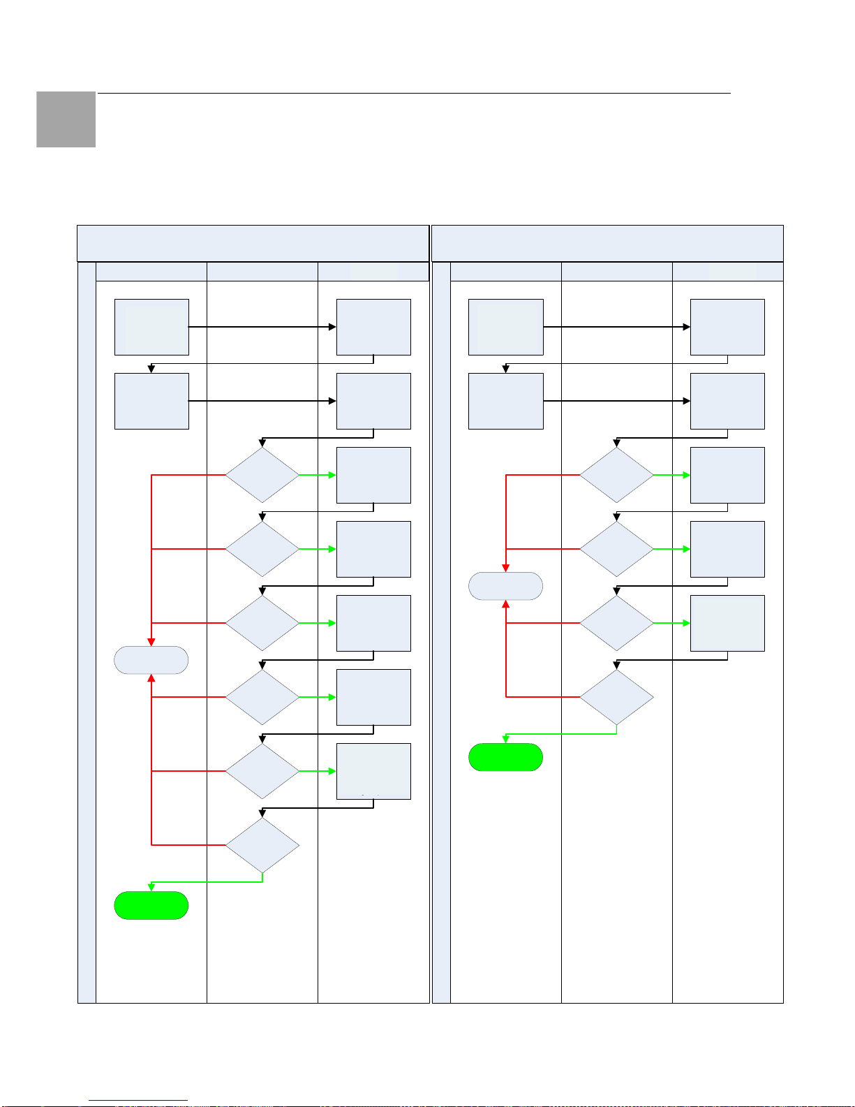
Advanced Operations 8
64
Switched Power Distribution Unit
EN
8.4.2 LDAP Technical Specifications
LDAP Authentication Process
Simple Bind Authentication Process
LDAP Server SentryClient
Initiate Sentry
session
Authentication
request with
Usename/
Password
Successful
Bind?
Username
found?
Successful
Bind?
Attribute
match?
Username
found?
Attribute name
compared to
Group
Membership
Attribute
Subtree search
starting from
User Search Base
DN with User
Search Filter
Prompt for login
credentials
Simple Bind using
User FQDN and
login password
Simple bind using
Search Bind
DN & Password
Subtree search
starting from
User Search Base
DN with User
Search Filter
Access Denied
Username groups
access rights
compared against
Sentry LDAP
groups
Group
match?
Access Granted
MD5 Bind Authentication Process
SentryLDAP ServerClient
Access Granted
Username groups
access rights
compared against
Sentry LDAP
groups
Access Denied
Initiate Sentry
session
Group
match?
SASL Digest-MD5
bind using
uppercase
username &
entered password
Subtree search
starting from
User Search Base
DN with User
Search Filter
Prompt for login
credentials
Attribute name
compared to
Group
Membership
Attribute
Attribute
match?
Authentication
request with
Usename/
Password
Successful
Bind?
Username
found?
Username groups
access rights
compared against
PDU LDAP groups
Initiate
PDU
session
Initiate
PDU
session
Username groups
access rights
compared against
PDU LDAP groups
Page 65

Advanced Operations 8
Switched Power Distribution Unit
65
EN
8.4.3 LDAPS Client Specifications
Secure Sockets Layer (SSL) version 3
Transport Layer Security (TLS) version 1 (RFC
2246)
x.509 version 3 Server Certificates (RFC 2459)
with RSA key sizes up to 4096 bits
Symmetric Cryptography Ciphers:
TLS_RSA_WITH_3DES_EDE_CBC_SHA (168bit)
TLS_RSA_WITH_DEX_CBC_SHA (56-bit)
TLS_RSA_WITH_AES_128_CBC_SHA (128-bit)
TLS_RSA_WITH_AES_256_CBC_SHA (256-bit)
Server certificates are accepted and used on –
the-fly
A NULL client certificate is sent to the server if a
client certificate is requested
8.5 TACACS+
The PDU family of products supports the Terminal
Access Controller Access Control System (TACACS+) protocol. This enables authentication
and authorization with a central TACACS+ server;
user accounts do not need to be individually created locally on each PDU device.
This allows administrators to pre-define and configure (in each PDU product, and in the TACACS+
server) a set of necessary TACACS+ privilege
levels, and users access rights for each. User’s
access rights can then be assigned or revoked
simply by making the user a member of one-ormore pre-defined PDU TACACS+ privilege levels.
User account rights can be added, deleted, or
changed within TACACS+ without any changes
needed on individual PDU products.
The PDU supports 16 different TACACS+ privilege
levels; 15 are entirely configurable by the system
administrator (1 is reserved for default Admin level
access to all PDU resources).
TACAC+ Command Summary
Command Description
Set Authorder Specifies the authentication
order for each new session at-
tempt
Set TACACS Enables/disables SSL support
Set TACACS Host Sets the IP address or host-
name of the TACACS server
Set TACACS Key Sets the TACACS encryption
key
Set TACACS Port Sets the TACACS server port
number
Show TACACS Displays TACACS configura-
tions
Add GrouptoTACACS Grants a TACACS account
access to one or more groups
Add OutlettoTACACS Grants a TACACS account
access to one or all outlets
Add PorttoTACACS Grants a TACACS account
access to one or serial ports
Delete GroupfromTACACS Removes access to one or
more groups for a TACACS ac-
count
Delete OutlettoTACACS Removes access to one or
more outlets for a TACACS ac-
count
Delete PortfromTACACS Removes access to one or
more serial ports for a TACACS
account
Set TacPriv Access Sets the access level for a
TACACS account
Set TacPriv Envmon Grants or removes privileges to
view input and environmental
monitoring status
List TacPrivs Displays access levels for all
TACACS accounts
List TacPriv Displays all accessible out-
let/groups/ports for a TACACS
account
Enabling and Setting up TACACS+ Support
There are a few configuration requirements for
properly enabling and setting up TACACS+ support. Below is an overview of the minimum requirements:
1. Enable TACACS+ support.
2. Define the IP address and domain component of at least one TACACS+server.
3. Set the TACACS+ key configured on the
supporting TACACS+server.
Enabling and disabling TACACS+ support:
The Set TACACS command is used to enable or
disable TACACS+ support.
Page 66

Advanced Operations 8
66
Switched Power Distribution Unit
EN
To enable or disable TACACS+ support:
At the Switched PDU: prompt, type set tacacs,
followed by enabled or disabled and press En-
ter.
Setting the TACACS+ server address:
The Set TACACS Host command sets the IP
address or hostname of the TACACS+ server.
To set the TACACS+ server address:
At the Switched PDU: prompt, type set tacacs,
followed by host1 or host2 and the TACACS+
server’s IP address or hostname. Press Enter.
Examples
The following command sets the primary TACACS+ server address to 98.76.54.32:
Switched PDU: set tacacs host1
98.76.54.32<Enter>
The following command sets the secondary TACACS+ server address to tacacs.rittal.com:
Switched PDU: set tacacs host2 tacacs.rittal.com<Enter>
Setting the TACACS+ encryption key:
The Set TACACS Key command sets the encryption key used to encrypt all data packets between
the PDU and the TACACS+ server. This key
must match the key configured on the TACACS+
server.
To set the encryption key:
At the Switched PDU: prompt, type set tacacs
key and press Enter.
At the TACACS+ Key: prompt, type an encryption
key of up to 60 alphanumeric and other typeable
characters - (ASCII 33 to 126 decimal) are allowed; encryption keys are case sensitive. Press
Enter. To specify no password, press Enter.
At the Verify TACACS+ Key: prompt, retype the
key. Press Enter. To verify no password, press
Enter at the prompt.
Example
Switched PDU: set tacacs key<Enter>
TACACS+ Key: <Enter>
Verify TACACS+ Key: <Enter>
For security, key characters are not displayed.
Note!
A key size of zero results in no encryption being applied which may not be
supported by the TACACS+ server and
is not recommended for a production
environment.
Changing the TACACS port:
With TACACS support enabled, the PDU sends
TACACS requests to the default TACACS port
number 49. This port number may be changed
using the Set TACACS Port command.
To change the TACACS port:
At the Switched PDU: prompt, type set tacacs port,
followed by the port number and press Enter.
Example
The following changes the TACACS port number
to 50:
Switched PDU: set tacacs port 50<Enter>
Setting the authentication order:
The Set Authorder command sets the authentication order for remote authentication sessions.
The PDU supports two methods for authentication
order - Remote -> Local and Remote Only.
The Remote -> Local method first attempts authentication with the TACACS+ server and if unsuccessful with the local user database on the
PDU device.
The Remote Only method attempts authentication
only with the TACACS+ server and if unsuccessful, access is denied.
Note!
With the Remote Only method, if authentication fails due to a communication failure with the TACACS+ server
automatic authentication fallback will
occur to authenticate with the local user
data base on the PDU device.
To set the authentication order:
At the Switched PDU: prompt, type set authorder, followed by remotelocal or remoteonly and
press Enter.
Page 67

Advanced Operations 8
Switched Power Distribution Unit
67
EN
Note!
Rittal recommends NOT setting the authentication order to Remote Only until
the TACACS+ has been fully configured
and tested.
Displaying TACACS+ configuration information:
The Show TACACS command displays TACACS+ configuration information.
To display the TACACS configuration information:
At the Switched PDU: prompt, type show tacacs
and press Enter.
Example
The following command displays the TACACS
configuration information:
Switched PDU: show tacacs<Enter>
TACACS+ Configuration
TACACS+: Enabled
Host 1: 98.76.54.32
Host 2: tacacs.rittal.com
Port: 50
TACACS+ Key: (Set)
Auth Order: Remote->Local
8.5.1 TACACS+ Privilege Levels
Setting TACACS+ account access level privileges:
The Set TacPriv Access command sets the access level privileges for a TACACS+ account.
The PDU has four defined access privilege levels;
Admin, User, On-Only and View-Only.
To set the access level privilege for a TACACS+ account :
At the Switched PDU: prompt, type set tacpriv
access, followed by admin, user, ononly or
viewonly, optionally followed by a TACACS+
account number and press Enter.
Examples
The following command sets the TACACS+ account access level for account 14 to Admin:
Switched PDU: set tacpriv access admin
14<Enter>
The following command sets the TACACS+ account access level for account 5 to User:
Switched PDU: set tacpriv access user 5<Enter>
Granting and removing input status viewing
privileges:
The Set TacPriv Envmon command grants or
removes input status viewing privileges to/from a
TACACS+ account.
To grant or remove input status viewing privileges for
a TACACS+ account:
At the Switched PDU: prompt, type set tacpriv
envmon, followed by on or off, optionally fol-
lowed by a TACACS+ account number and press
Enter.
Example
The following command grants input status viewing privileges to the TACACS+ account 5:
Switched PDU: set tacpriv envmon on 5<Enter>
Displaying the TACACS+ access privilege
levels:
The List TacPrivs command displays all TACACS+ accounts with their access privilege levels.
To display TACACS+ account access privilege levels:
At the Switched PDU: prompt, type list tacprivs
and press Enter.
Example
The following command displays all TACACS+
account with their access privilege level:
Switched PDU: list tacprivs<Enter>
TACACS Access Environ-
mental
Account Name Level Monitoring
TACAdmin Admin Allowed
PowerUser User Allowed
User On-Only Not Allowed
Guest View-Only Not Allowed
Adding outlet access to a TACACS+ account:
The Add OutletToTACACS command grants a
TACACS+ account access to one or all outlets.
To grant access for more than one outlet, but not
Page 68

Advanced Operations 8
68
Switched Power Distribution Unit
EN
all outlets, you must use multiple Add OutletToTACACS commands.
To grant outlet access to a TACACS+ account:
At the Switched PDU: prompt, type add outlettotacacs, optionally followed by an outlet name and
a TACACS+ account number. Press Enter, or
Type add outlettotacacs all, followed by a TA-
CACS+ account number and press Enter.
Examples
The following commands grant the a TACACS+ account 5 access to outlets A1 and Webserver_1:
Switched PDU:add outlettotacacs .a1 5<Enter>
Switched PDU:add outlettotacacs WebServer_1
5<Enter>
Deleting outlet access for a TACACS+ account:
The Delete OutletFromTACACS command removes a TACACS+ account’s access to one or all
outlets. You cannot remove access to any outlet
for an administrative level account.
To delete outlet access for a TACACS+ account:
At the Switched PDU: prompt, type delete outletfromtacacs, optionally followed by an outlet
name and a TACACS+ account number. Press
Enter, or
Type delete outletfromtacacs all, followed by a
TACACS+ account number and press Enter.
Adding outlet group access to a TACACS+
account:
The Add GroupToTACACS command grants a
TACACS+ account access to an outlet group. To
grant access for more than one outlet group, you
must use multiple Add GroupToTACACS commands.
To grant outlet group access to a TACACS+ account:
At the Switched PDU: prompt, type add grouptotacacs, optionally followed by an outlet group
name and a TACACS+ account number. Press
Enter.
Examples
The following commands grants to a TACACS+
account number 5 access to the outlet groups
ServerGroup_1 and ServerGroup_2:
Switched PDU:add grouptotacacs servergroup_1
5<Enter>
Switched PDU:add grouptotacacs servergroup_2
5<Enter>
Deleting outlet group access for a TACACS+
account:
The Delete GroupFromTACACS command removes a TACACS+ account’s access to an outlet
group. You cannot remove access to any group
for an administrative level account.
To delete outlet group access for a TACACS+ account:
At the Switched PDU: prompt, type delete groupfromtacacs, optionally followed by a outlet group
name and a TACACS+ account number. Press
Enter.
Adding serial port access to a TACACS+ account:
The Add PortToTACACS command grants a TACACS+ account access to the serial port.
To grant serial port access to a TACACS+ account:
At the Switched PDU: prompt, type add porttotacacs console and a TACACS+ account number.
Press Enter.
Deleting serial port access for a TACACS+
account:
The Delete PortFromTACACS command removes
a TACACS+ account’s access to the serial port.
You cannot remove access to the serial port for
an administrative level account.
To delete serial port access for a TACACS+ account:
At the Switched PDU: prompt, type delete portfromtacacs console and a TACACS+ account
number. Press Enter.
Displaying TACACS account access:
The List TacPriv command displays all access rights
for a TACACS+ account.
To display TACACS account access:
At the Switched PDU: prompt, type list tacpriv,
optionally followed by a TACACS+ account. Press
Enter.
Page 69

Advanced Operations 8
Switched Power Distribution Unit
69
EN
Example
The following command displays information
about the TACACS+ account 1:
Switched PDU: list tacpriv 1<Enter>
TACACS+ Privilege Level: 1
Outlet Outlet
ID Name
.A1 DataServer_1
.A2 WebServer_1
Groups:
ServerGroup_1
ServerGroup_2
More (Y/es N/o): Y
Ports:
Port ID Port Name
Console Console
Members of the TACACS privilege level 1 account may access the following outlets, outlet
groups and serial ports: outlet A1 which has a
descriptive name of DataServer_1, outlet A2
which has a descriptive name of WebServer_1,
group ServerGroup_1 group ServerGroup_2 and
Console serial port.
TACACS+ Technical Specifications
Authentication START Packet includes:
action = 1 (TAC_PLUS_AUTHEN_LOGIN)
priv_lvl = 0 (TAC_PLUS_PRIV_LVL_MIN)
authen_type = 1
(TAC_PLUS_AUTHEN_TYPE_ASCII)
service = 1 (TAC_PLUS_AUTHEN_SVC_LOGIN)
user = (entered username)
port = (access path into the PDU)
rem_addr = ‘PDU3_xxxxxx’ (xxxxxx is last six
digits of MAC address)
data = ‘‘ (null)
Note!
The password is sent in a CONTINUE
packet.
Authorization REQUEST Packet includes:
authen_method = 6
(TAC_PLUS_AUTHEN_METH_TACACSPLUS)
priv_lvl = 0 (TAC_PLUS_PRIV_LVL_MIN)
authen_type = 1
(TAC_PLUS_AUTHEN_TYPE_ASCII)
authen_service = 1
(TAC_PLUS_AUTHEN_SVC_LOGIN)
user = (entered username)
port = (access path into the PDU)
rem_addr = ‘PDU3_xxxxxx’ (xxxxxx is last six
digits of Ethernet MAC address)
service = ‘shell’ (for exec)
cmd = ‘‘ (null)
Note!
The access paths into the PDU which
support TACACS+ are ‘Console’, ‘Telnet’, ‘SSH’, ‘HTTP’ and ‘HTTPS’. In the
case of ‘Console’ and ‘Modem’, an administrator is allowed to rename these
ports in which case the assigned name
is used.
8.6 Logging
The PDU family of products supports logging of
system events both internally and externally. An
internal log of more than 4000 events is automatically maintained and is reviewable by administrative users. For permanent/long-term log storage,
PDU supports the Syslog protocol. And for immediate notification, PDU supports Email notifications.
Log entries include a sequential entry number, a
date/time stamp and an event message. The
event message is preceded with a message ‘type’
heading and if the event is tied to a user, the
username will be included.
Note!
For date/time stamp support, SNTP
server support must be configured.
The PDU supports the following event message
headers:
• AUTH: All authentication attempts.
• POWER: All power state change requests.
• CONFIG: All system configuration changes.
• EVENT: All general system events.
Example: over/under threshold event.
Internal System Log
The internal system log is stored in the local
memory and has support for up to 4097 continuously aging entries. The internal system log is
only available to administrative users. For instructions on reviewing the internal log,
Page 70

Advanced Operations 8
70
Switched Power Distribution Unit
EN
Syslog
The PDU’s Syslog support is RFC3164-compliant
and enables off-PDU viewing and storage of log
messages. The PDU supports external logging to
up to two Syslog servers.
Syslog Command Summary
Command Description
Set Syslog HostIP Sets the IP address of the
Syslog server
Set Syslog Port Sets the Syslog server port
number
Show Syslog Displays all Syslog configura-
tion information
Setting the Syslog server IP address:
The Set Syslog HostIP command sets the TCP/IP
address of the Syslog server.
To set the Syslog server IP address:
At the Switched PDU: prompt, type set syslog,
followed by hostip1 or hostip2 and the Syslog
server’s IP address. Press Enter.
Example
The following command sets the primary Syslog
server IP address to 56.47.38.29:
Switched PDU: set syslog hostip1
56.47.38.29<Enter>
Changing the Syslog server port:
With Syslog support enabled, the Syslog server
watches and responds to requests on the default
Syslog port number 514. This port number may
be changed using the Set Syslog Port command.
To change the Syslog port:
At the Switched PDU: prompt, type set syslog
port, followed by the port number and press Enter.
Example
The following changes the Syslog port number to
411:
Switched PDU: set syslog port 411<Enter>
Displaying Syslog configuration information:
The Show Syslog command displays Syslog configuration information.
To display the Syslog configuration information:
At the Switched PDU: prompt, type show syslog
and press Enter.
Example
The following command displays the Syslog configuration information:
Switched PDU: show syslog<Enter>
SYSLOG Configuration
Primary Syslog Server IP Address:
56.47.38.29
Secondary Syslog Server IP Address:
0.0.0.0
Syslog Server Port:
411
8.6.1 Email
Email Command Summary
Command Description
Set Email Enables or disables Email
notification support
Set Email SMTP Host Sets the SMTP Host IP
address or hostname
Set Email SMTP Port Sets the SMTP server port
number
Set Email From Sets the email ‘From’ ad-
dress
Set Email PrimaryTo Sets the primary recipient
email address
Set Email SecondaryTo Sets the secondary recipient
email address
Set Email Event Enables or disables notifica-
tion of general system events
Set Email Auth Enables or disables notifica-
tion of all authentication attempts
Set Email Power Enables or disables notifica-
tion of power state change
requests
Set Email Config Enables or disables notifica-
tion of configuration changes
Show Email Displays all Email configura-
tion information
Enabling or disabling Email notification Support:
The Set Email command enables or disables
Email notification support.
To enable or disable Email notification support:
At the Switched PDU: prompt, type set email,
followed by enabled or disabled and press En-
ter.
Page 71

Advanced Operations 8
Switched Power Distribution Unit
71
EN
Setting the SMTP server address:
The Set Email Host command sets the IP address
or hostname of the SMTP server.
To set the SMTP server address:
At the Switched PDU: prompt, type set email
smtp host, followed by the SMTP server’s IP
address or hostname and press Enter.
Examples
The following command sets the SMTP server
address to 55.55.55.55:
Switched PDU: set email smtp
55.55.55.55<Enter>
The following command sets the SMTP server
address to email.rittal.com:
Switched PDU: set email smtp
email.rittal.com<Enter>
Changing the SMTP server port:
With SMTP support enabled, the PDU sends
SMTP requests to the default SMTP port number
25. This port number may be changed using the
Set Email SMTP Port command.
To change the TACACS port:
At the Switched PDU: prompt, type set email
smtp port, followed by the port number and press
Enter.
Example
The following changes the SMTP port number to
5555:
Switched PDU: set email smtp port 5555<Enter>
Setting the ‘From’ email address:
The Set Email From command sets the ‘from’
email address. By default, this is set to ‘PDU3_’
plus the last three octets of the unit’s MAC address. Example: ‘PDU3_510c90@’
To set the ‘From’ email address:
At the Switched PDU: prompt, type set email
from, followed by the originating email address
and press Enter.
Example
The following command sets the ‘from’ email address to Rack14PDU1@rittal.de:
Switched PDU: set email from
[email protected]<Enter>
Setting the ‘To’ email address:
The Set Email PrimaryTo and Set Email SecondaryTo commands set the recipient email addresses.
To set the ‘To’ email address:
At the Switched PDU: prompt, type set email,
followed by primaryto or secondaryto and the
destination email address. Press Enter.
Examples
The following command sets the primary ‘to’ email
address to [email protected]:
Switched PDU: set email primaryto DayAd[email protected]<Enter>
The following command sets the secondary ‘to’
email address to [email protected]:
Switched PDU: set email secondaryto
[email protected]<Enter>
Enabling or disabling event notification types:
The Set Email Event, Set Email Auth, Set Email
Power and Set Email Config commands enable or
disable email notification of the event types as
described.
To enable or disable event notification types:
At the Switched PDU: prompt, type set email,
followed by event, auth, power or config and
enabled or disabled. Press Enter.
Examples
The following command sets the enables email
notification general system events:
Switched PDU: set email event enabled<Enter>
The following command sets the disables email
notification authentications attempts:
Switched PDU: set email auth disable<Enter>
Page 72

Advanced Operations 8
72
Switched Power Distribution Unit
EN
Displaying Email configuration information:
The Show Email command displays Email configuration information.
To display the Email configuration information:
At the Switched PDU: prompt, type show email
and press Enter.
Example
The following command displays the Email configuration information:
Switched PDU: show email
Email Configuration
Email Notifications: Enabled
SMTP Host: email.rittal.de
SMTP Port: 5555
'From' Address: [email protected]
Primary 'Send To' Address: [email protected]
Secondary 'Send To' Address: NiteAd[email protected]
Include EVENT Messages: Enabled
Include AUTH Messages: Disabled
Include POWER Messages: Disabled
Include CONFIG Messages: Disabled
8.7 Upload/Download
The PDU family of product supports the ability to
upload and download system configurations using
a standard FTP client. This feature enables for
backup and restoration of system configuration as
well as upload of ‘template’ configurations to ease
large initial equipment deployments.
Upload/Download Command Summary
Command Description
Set FTP Server Enables or disables the FTP
server
Show FTP Displays FTP configuration
information
PDU Integrated FTP Server
The PDU supports an integrated FTP Server
which must be enabled for Upload/Download
support. The PDU FTP Server supports a single
user at a time. Once an administrative user has
authenticated with the PDU FTP Server, standard
FTP client commands may be used to upload or
download PDU configurations.
Note!
The integrated FTP Server does NOT
support web browser FTP file transfers.
A non-web-browser is required for all
Upload/Download requests.
Enabling and disabling the FTP server:
The Set FTP Server command is used to enable
or disable the integrated FTP server.
To enable or disable the FTP server:
At the Switched PDU: prompt, type set ftp
server, followed by enabled or disabled and
press Enter.
FTP Configuration Files
The PDU FTP server supports upload/download
of two configuration files: CONFIG.BIN and NETWORK.INI. These files may be uploaded or
downloaded using FTP PUT and GET operations.
• CONFIG.BIN This file contains the entire configuration of the PDU excluding TCP/IP settings, serial/factory-only configurations, the
x.509 certificate (SSL) and SSH keys. This file
in encoded to keep all data (including usernames, passwords etc.) out of plain view. This
file is NOT editable.
• FTP.INI This file contains only the FTP
settings (FTP Host, username, password,
filepath, filename and automatic updates support). This file is user readable and editable
‘plain text’ file.
• NETWORK.INI This file contains only the
TCP/IP settings (IP address, subnet mask,
gateway, DNS1 and DNS2). This file is user
readable and editable ‘plain text’ file.
• SNTP.INI This file contains only the SNTP
settings (SNTP Hosts and GMT offset). This
file is user readable and editable ‘plain text’ file.
Note!
The CONFIG.BIN file while encoded is
not encrypted and susceptible to decoding using simple tools.
Rittal recommends the secure storage of
CONFIG.BIN backup images.
Page 73

Appendices 9
Switched Power Distribution Unit
73
EN
Upload/Download Process
GETting a configuration file (Download):
1. Open the FTP client.
In a Windows environment, in the Run
window type ftp and press Enter.
2. At the prompt, type open, followed by
the IP address of the PDU and press
Enter.
FTP> open 12.34.56.78<Enter>
3. Authenticate with the appropriate administrative username and password.
4. At the prompt, type get, followed by the
filename and press Enter.
FTP> get config.bin<Enter>
5. At the prompt, type close to close the
connection to the PDU.
FTP> close
PUTting a configuration file (Upload):
Note!
Uploading the CONFIG.BIN file takes
considerably longer than the NETWORK.INI file.
When uploading both, Rittal recommends uploading the NETWORK.INI file
first.
1. Open the FTP client.
In a Windows environment, in the Run window type ftp and press Enter.
2. At the prompt, type open, followed by the
IP address of the PDU and press Enter.
FTP> open 12.34.56.78<Enter>
3. Authenticate with the appropriate adminis-
trative username and password.
4. At the prompt, type put, followed by the
filename and press Enter.
FTP> put network.ini<Enter>
5. At the prompt, type close to close the con-
nection to the PDU and force a restart of
the device.
FTP> close
9 Appendices
9.1 Resetting to Factory Defaults
You may reset the non-volatile RAM that stores
all configurable options. This clears all administrator-editable fields and resets all command line
configurable options to their default values, including all user accounts.
You may reset the unit to factory defaults from the
command line or the HTML interface, or by pressing the reset button. You must have administrator-level privileges to issue the command. Using
the reset button may be necessary when a forgotten password prevents administrator login. Each
of the methods updates the current working configuration to the factory defaults.
To reset to factory defaults
Note!
Resetting the unit resets all TCP/IP and
Telnet/Web configurations. Reconfiguring the TCP/IP and Telnet/web settings
will be required.
From the HTML interface
On the Restart page in the Tools section of the
HTML interface, select Restart and reset to fac-
tory defaults from the drop-down menu and
press Apply.
From the command line
At the Switched PDU: prompt, type restart fac-
tory and press Enter.
Using the reset button
Locate the recessed reset button directly beside
the Serial & Ethernet ports. You will need a nonconductive, non-metallic tool that fits inside the
recess.
Note!
This method will NOT work if the reset
button has been disabled by the administrator.
Insert the tool in the recess, then depress and
hold the reset button for at least ten seconds.
Note!
If the reset button is depressed and held
for more than 15 seconds, the reset will
abort.
Page 74
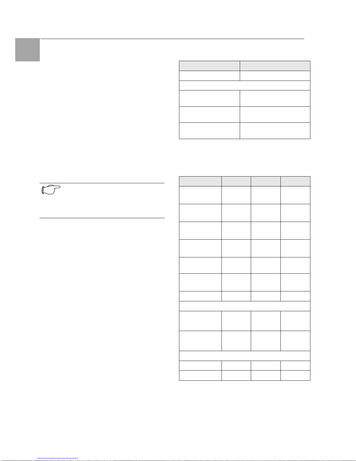
Technical Specifications 10
74
Switched Power Distribution Unit
EN
To reset to factory defaults, except network
settings
From the HTML interface
On the Restart page in the Tools section of the
HTML interface, select Restart and reset to fac-
tory defaults, except network from the dropdown menu and press Apply.
From the command line
At the Switched PDU: prompt, type restart fac-
tory keepnet and press Enter.
9.2 Uploading Firmware
You may upload new versions of firmware using
File Transfer Protocol (FTP). This allows access
to new firmware releases for firmware improvements and new features additions.
Note!
To begin an FTP upload session, you
must first configure the FTP Host address, username/password, filename
and filepath.
You may initiate an FTP upload session by issuing a command or from the HTML interface.
Upon initiating an FTP upload session, the unit
will restart and upload the firmware file specified
with the FTP Filename command from the previously configured FTP Host.
You must have administrator-level privileges to
initiate an upload.
To initiate an FTP upload session from the
HTML interface
On the Restart page in the Tools section of the
HTML interface, select Restart and upload
firmware via FTP from the drop-down menu and
press Apply.
To initiate an FTP upload session from the
command line
To initiate an FTP firmware upload session:
At the Switched PDU: prompt, type restart
ftpload and press Enter.
10 Technical Specifications
Switched PDU
Material Sheet steel
Environment
Temperature 0 - +40 °C
+32 - +104 °F
Storage temperaturer -40 - +85 °C
-40 - +185 °F
Humidity 10 - 90 % RH, not con-
densing
Tab. 4 Physical data
10.1 Technical Data
DK 7856 .530 .540 .550
Height
in mm
1260 1755 1270
Width
in mm
45 45 90
Depth
in mm
57 57 57
Weight
in kg
4,6 8,7 8,0
SupplyVoltage
230V 400V 230V
Frequency
(in Hz)
50/60 50/60 50/60
Power Supply
1 x 32A 3 x 32A 2 x 32A
Connection
Plug
(1-phase)
.
-
.
(2x)
Plug
(3-phase)
-
.
-
Slots
C13
2 x 8 3 x 8 2 x 16
C19
- - -
Tab. 5 Technical data
Page 75
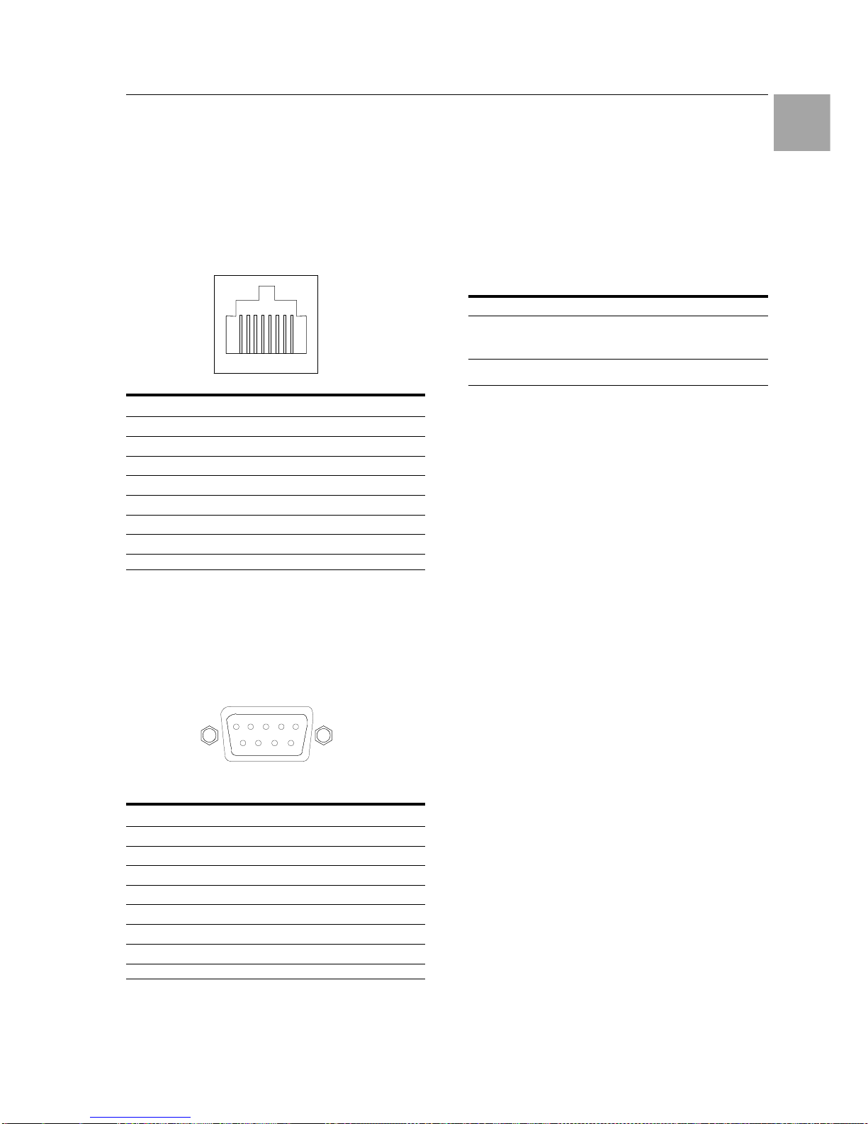
Technical Specifications 10
Switched Power Distribution Unit
75
EN
10.2 Data Connections
RS-232 port
Switched PDUs are equipped standard with an
RJ45 DTE RS-232c serial port. This connector
may be used for direct local access or from other
serial devices such as a terminal server. An RJ45
crossover cable is provided for connection to an
RJ45 DCE serial port.
Pin DTE-Signal Name Input/Output
1 Request to send RTS Output
2 Data Terminal Ready DTR Output
3 Transmit Data TD Output
4 Signal Ground
5 Signal Ground
6 Receive Data RD Input
7 Data Set Ready DSR Input
8 Clear to Send CTS Input
RJ45 to DB9F serial port adapter
Additionally, an RJ45 to DB9F serial port adapter
is provided for use in conjunction with the RJ45
crossover cable to connect to a PC DB9M DCE
serial port. The adapter pinouts below reflect use
of the adapter with the provided RJ45 crossover
cable.
Pin DTE-Signal Name Input/Output
1
2 Receive Data RD Output
3 Transmit Data TD Input
4 Data Terminal Ready DTR Input
5 Signal Ground
6 Data Set Ready DSR Output
7 Request to Send RTS Input
8 Clear to Send CTS Output
10.3 LED Indicators
Input/Branch/Phase Current
Units are equipped with 7-segment LEDs for reporting of input, branch or phase current loading.
Loading is reported in amperes and is displayed
in ½ amp increments under 10A and whole amp
increments at and above 10A. Additionally, the
LED may display codes for events detected by
the system for immediate local notification.
Behavior/Code Event description
Blinking On 3-phase devices – Indicates that
phase loads exceed out-of-balance
threshold
FE PDU has detected a removed/blown
fuse
Outlets
Units are equipped with a status LED for each
power receptacle. A lit/on LED indicates that
power is being supplied at the port and a darkened/off LED indicates that there is no power at
the port.
67 543218
12345
6789
Page 76

Technical Specifications 10
76
Switched Power Distribution Unit
EN
10.4 Regulatory Compliance
Product Safety
Units have been safety tested and certified to the
following standards:
• USA/Canada UL 60950:2003 and
CAN/CSA 22.2 No. 60950-1-03
• European Union EN60950-1:2001
This product is also designed for Norwegian IT
power system with phase-to phase voltage 230V.
USA Notification
Note: This equipment has been tested and found
to comply with the limits for a Class A digital device, pursuant to part 15 of the FCC Rules.
These limits are designed to provide reasonable
protection against harmful interference when the
equipment is operated in a commercial environment. This equipment generates, uses, and can
radiate radio frequency energy and, if not installed and used in accordance with the instruction manual, may cause harmful interference to
radio communications. Operation of this equipment in a residential area is likely to cause harmful interference in which case the user will be
required to correct the interference at his own
expense.
Modifications not expressly approved by the
manufacturer could void the user's authority to
operated the equipment under FCC rules.
Canadian Notification
This Class A digital apparatus complies meets all
requirements of the Canadian InterferenceCausing Equipment Regulations.
Cet appareil numérique de la classe A respecte
toutes les exigencies du Règlement sur le matériel brouilleur du Canada.
European Union Notification
Products with the CE Marking comply with both
the EMC Directive (89/336/EEC) and the Low
Voltage Directive (73/23/EEC) issued by the
Commission of the European Community.
Compliance with these directives implies conformity to the following European Norms:
• EN55022 Electromagnetic Interference
• EN55024 Electromagnetic Immunity
• EN60950-1 Product Safety
• EN61000-3 Harmonics and Flicker
Products with the following mark comply with the
RoHS Directive (2002/95/EC) issued by the
Commission of the European Community.
Japan
この装置は、情報処理装置等電波障害自主規制協
議会(VCCI)の基準に基づくクラスA情報技
術装置です。この装置を家庭環境で使用すると電
波妨害を引き起こすことがあります。この場合に
は使用者が適切な対策を講ずるよう要求されるこ
とがあります。
Recycling
Rittal encourages the recycling of its
products. Disposal facilities, environ-
mental conditions and regulations vary
across local, state and country jurisdictions, so
Rittal encourages consultation with qualified professional and applicable regulations and authorities within your region to ensure proper disposal.
Waste Electrical and Electronic Equipment
(WEEE)
In the European Union, this label indicates that this product should not be disposed of with household waste. It should
be deposited at an appropriate facility to
enable recovery and recycling.
Page 77
Maintenance and Cleaning 11
Switched Power Distribution Unit
77
EN
11 Maintenance and Cleaning
The Rittal Switched Power Distribution Unit is a
maintenance-free system. The housing does not
need to be opened for the installation or during
operation
Note!
Opening the housing or any accessory
components will void any warranty and
liability claims.
11.1 Cleaning
Warning!
Danger of damage!
Do not use any aggressive substances, such as white spirit, acid,
etc., for cleaning because such substances can damage the unit.
Use a slightly moistened soft cloth to clean the
housing.
12 Customer Service
If you have any technical questions or questions
concerning our product spectrum, contact the
following service address:
Tel.: +49 (0)2772/505-1855
http://www.rimatrix5.de
E-Mail: [email protected]
Note!
To allow us to process your enquiry
quickly and correctly, please always
specify the article number in the subject
line for e-mails.
Further information and the current operating
guides and updates are available for download
under Security on the Rimatrix5 homepage:
http://www.rimatrix5.de/service_support/download
s.asp
 Loading...